

Page 1

8000 Series User Manual
Flexible Linear Lighting System
The versatile indoor and outdoor water resistant lighting solution.
Page 2
2
cabled.optiled.com
ELECTRICAL RATING
To avoid any malfunctions of the system, and to protect against electrical shock, re or physical
injury, please observe the following:
This system has been designed to work with 100-240 volt AC current. Connection to a line
•
voltage other than that may create a safety and re hazard and may damage the system. If you
are unsure of the type of power supply to your home, consult your local power company or a
qualied service technician.
When using electrical products, basic precautions should always be followed including the
following electrical ratings for models listed below:
C8K-18-CW / C8K-18-WW : 120 V, 0.5 A ; Output : 24V, 0.75A
C8K-30-CW / C8K-30-WW : 120 V, 0.5 A ; Output : 24V, 1.25A
C8K-60-CW / C8K-60-WW : 120V, 1.0 A ; Output : 24V, 2.5A
GROUNDING INSTRUCTIONS
This product must be grounded. If it should malfunction or breakdown, grounding provides a
equipped with a cord having an equipment-grounding conductor and a grounding plug. The
accordance with all local codes and ordinances.
WARNING – Improper connection of the equipment-grounding conductor is able to result in a
whether the product is properly grounded. Do not modify the plug provided with the product
- If it will not t the outlet, have a proper outlet installed by a qualied electrician.
Ground Fault Circuit Interrupter (GFCI) protection should be provided on the circuits or outlet
•
to be used for the outdoor use exible lighting product. Receptacles are available with built-
in GFCI protection for this measure of safety. If you are unsure of the type of outlet, consult a
qualied service technician to install a GFCI receptacle.
or SJTOW.
Model Numbers:
C8K-18-CW
,
C8K-30-CW
,
C8K-60-CW
,
C8K-18-WW
,
C8K-30-WW
,
C8K-60-WW.
WARNING:
A WARNING alerts you to the possibility of serious injury
or death if you do not follow the instructions.
CAUTION:
A CAUTION alerts you to the possibility of damage to or destruction
of the equipment if you do not follow the instructions.
An IMPORTANT alerts you to follow the instructions listed to
avoid the possibility of installation error or possible damage to or destruction of the
!
!
!
WARNING –
When using outdoor use portable lighting products, basic safety precautions should
always be followed to reduce the risk of re, electric shock, and personal injury, including the following:
Page 3

cabled.optiled.com
3
POWER SOURCE
•
outlet installed by a qualied electrician.
qualied service technician.
OPERATION
•
or when unused for long periods of time to prevent damage.
tightly secured to preclude the entry of water.
•
vision.
LOCATION
•
or other liquids.
The CabLED strip and components are rated IP65, weather proof only. Do not submerge the
exible lighting in liquids, or use the product in the vicinity of standing water or other liquids.
ignite.
water or other liquids.
•
•
INSTALLATION
Safety measures must be observed at all times during the installation of this product. Use proper
safety gear and tools during the installation process to prevent physical injury.
•
or the current National Electric Code (NEC). Improper installation may cause a possible shock
or re hazard.
To avoid electrical shock and/or damage to the system, do not handle the components with wet
•
Always make sure the CabLED strip is disconnected from the power source before cutting,
•
connecting, mounting or modifying in any way. Do NOT dismantle the CabLED strip itself.
•
WARNING:
strip prior to plugging into receptacle.
!
Page 4
4
cabled.optiled.com
INSTALLATION (CONTINuEd)
•
CabLED strip can only be cut at every 7.09 inches (18cm) and must be cut exactly on the
indicated mark.
indicated.
Create a layout plan before installation. Follow steps to locate power supply and determine
suitable mounting methods and required connectors and accessories. Measure and calculate
the required length of CabLED before beginning installation.
CabLED connectors have sharp pins inside. Follow instructions when handling.
•
install and mount.
Secure this exible strip using only the hangers or clips provided. Do not secure this product
•
or its cord with staples, nails, or like means that may damage the insulation.
CLEANING
Clean only with a dry or slightly damp cloth. Do not use any
acid or alkaline liquids,
cleansing
agents or solvents. Unplug the system from the wall outlet before cleaning.
NON-uSE PERIOdS
When left unused for long periods of time, the system should be unplugged from the
AC outlet.
SERVICE
Always remove the AC power adapter from the electrical outlet before adjusting or inspecting
the system. Inspect your system periodically.
connectors. There are no user-serviceable parts.
Opening the cabinets may present a shock hazard, and any modication to the product will
void your warranty.
immediately and consult an authorized service center.
AND UNDERSTAND THE INSTRUCTIONS IN THIS MANUAL.
!
CabLED is a registered trademark. All the information in this document is Copyrighted © 2011,
OPTILED Lighting International Limited, All rights reserved.
Page 5

Table of Contents
cabled.optiled.com 5
Important Safety Information 2-4
Table of Contents
.................................................................
5
Introduction
.....................................................................
6
About This Manual
.........................................................
6
About CabLED™ 8000 Series
..................................................
6
Possible Applications
............................................................
7- 11
Kitchen Cabinets
..........................................................
7
Patios
...................................................................
8
Indoor Staris
..............................................................
9
Outdoor Stairs
............................................................
10
Walkways
................................................................
11
Design Guidelines
12
CabLED™ Component Layout
13
CabLED™ Component Overview
14 -18
CabLED™ Strip
14
Power Supplies
14
Connectors
...........................................................
15 -16
Mounting Options
.........................................................
17
DIY Systems
..............................................................
18
Accessories
...............................................................
18
Step 1: Plan Installation
19
Plan Your Project
..........................................................
19
What is the Purpose of Your Project?
............................................
19
Warm White or Cool White?
..................................................
19
Step 2: Prepare for Installation
19-21
2.1 Determine Components Needed
19
2.2 Measure and Mark the Area
...............................................
20
2.3 Select Power Supply
....................................................
20
2.4 Mounting Options
......................................................
21
Step 3: Begin Installation
22
3.1 Measure, Mark and Cut CabLED™
...........................................
22
3.2 Mark CabLED™
........................................................
22
3.3 Cut CabLED™
.........................................................
22
Step 4: Install Connectors
23-30
4.1 Install PS-Link Connector
.................................................
23
4.2 Install End Cap
........................................................
23
4.3 Install I-Connector
......................................................
24
4.4 Install Jumper Cable
....................................................
25
4.5 Install L-Connector
.....................................................
26
4.6 Install T-Connector
......................................................
27
4.7 Install U-Connector
.....................................................
28
4.8 Install X-Connector
.....................................................
29
4.9 Install 4 Way Power Splitter
...............................................
30
Tes t
...................................................................
30
Step 5: Install Accessories
30
5.1 Install Inline Dimmer
.....................................................
31
Tes t
...................................................................
23
4.2 Mount Inline Dimmer
...................................................
23
Step 6: Mount CabLED™
32-36
6.1 Mark Placement for Brackets
...............................................
32
6.2 Use One of the Following Five Methods to Mount CabLED™
....................
32-36
Step 7: Mount Power Supply
37
Step 8: Connect to Power
37
Troubleshooting
38
Page 6
LED Strip
The exible CabLED strip uses CREE High Brightness LED lights. They are set every
inch and can be cut every 7.09 inches (18cm) up to lengths of 49.2 feet (15m). The
strips are available in Cool White (6500K), a bright, bluish white generally used for
task lighting and Warm White (3500K) a yellowish white more commonly used in
Connectors
A variety of easy-to-use connectors are designed for specic uses in dierent
installations. The connectors are used to attach sections of CabLED strip together
at virtually any angle to form endless congurations, as well as connect the strip to
the power supply.
Accessories
The Inline On/O Dimmer Switch is mounted with your system, adding dimmer
and power functions when connecting to an outlet not controlled by a light
switch. It oers full dimming range, fades the CabLED system on and o, and
Power
are separated by suitable plugs for each region. After identifying the correct
supply for each installation.
qualied electrician.
Mounting
A choice of ve mounting solutions are available.
Introduction
6
cabled.optiled.com
About CabLED™ 8000 Series
The CabLED 8000 Series consists of ve components, which may be combined to customize
each application. All components are rated IP65, suitable for indoor or outdoor installations.
AND UNDERSTAND THE INSTRUCTIONS IN THIS MANUAL.
!
The 8000 Series system includes an assortment of components to cover a variety of
follow the instructions in the order presented in this manual and be sure to observe all
warnings and cautions.
About This Manual
Thank you for purchasing your CabLED 8000 system. This manual is divided into sections
designed to make every installation easy for you. We have provided several typical indoor and
outdoor applications with helpful tips to help you visualize your potential CabLED projects.
suggest you review these manuals to fully understand and take advantage of all the features.
The 8000 Series oers great exibility, therefor it is very important to begin each installation
with a detailed plan. Go through the steps and options in this manual to determine the required
components for your needs. Please follow the instructions in the order presented in this manual
and be sure to observe all warnings and cautions.
Page 7
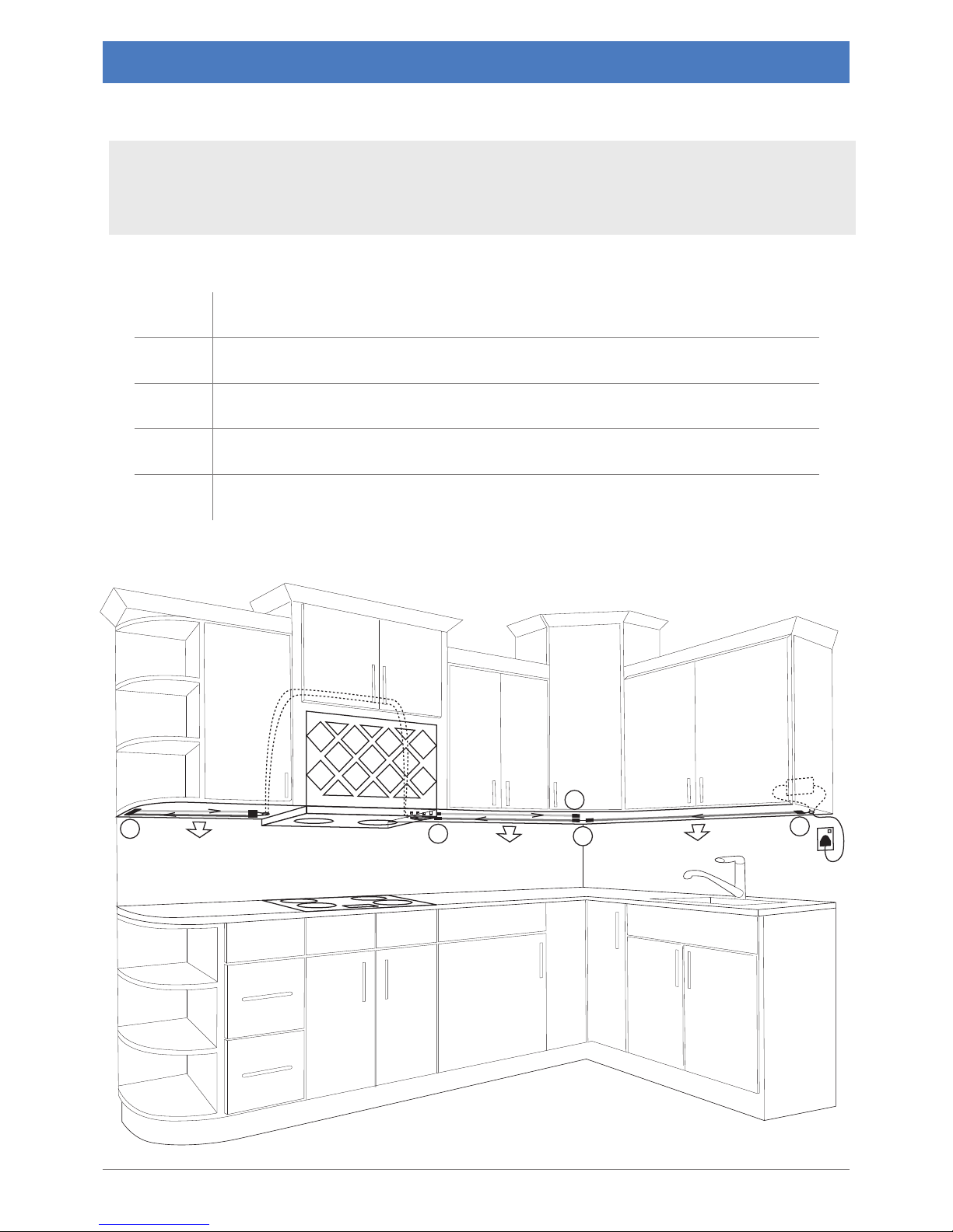
Possible Applications
cabled.optiled.com 7
E
End Cap
J
Jumper Cable (There are two lengths used here)
P
PS-Link Connector
PS
Power Supply
U
U-Connector
PS
P
J
E
J
U
Components
In this scenario, the power supply is connected to an AC outlets connected to a light switch. We have used
two strips in work areas that require more light joined with a U-Connector at one end and a short Jumper
Cable on the other. A longer Jumper Cable is hidden in the cabinet above the stove. The following chart
lists the components used for this scenario.
Kitchen Cabinets
Page 8
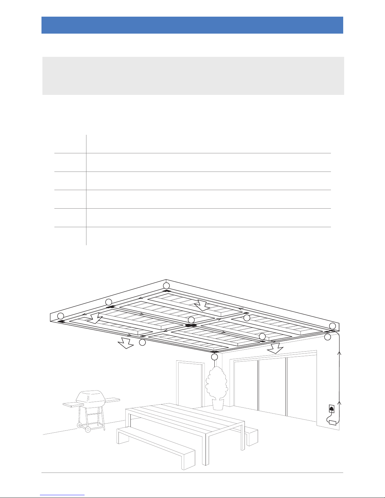
Possible Applications
8 cabled.optiled.com
This scenario turns your patio into the perfect entertainment area. The power supply is mounted well
above the ground so it cannot be submerged in water. The following chart lists the components used for
this scenario.
Patios
E
End Cap
L
L-Connector
P
PS-Link Connector
PS
Power Supply
T
T-Connector
X
X-Connector
PS
P
L
T
L
L
E
X
E
E
E
Components
Page 9
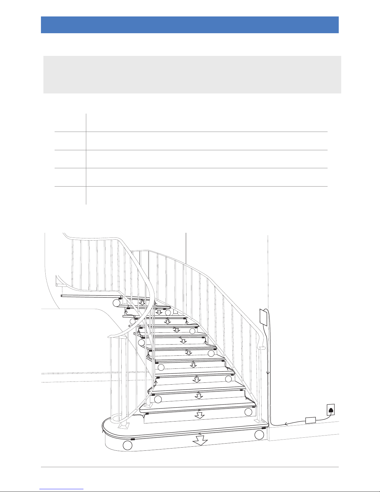
Possible Applications
The CabLED strips are mounted under the lip on each step, shining the light down on the step. Use the
Inline Dimmer to adjust the light level to keep your stairway softly lit. The Jumper Cables are hidden
behind the steps. The following chart lists the components used for this scenario.
Indoor Stairs
E
End Cap
J
Jumper Cable
N
Inline Dimmer
P
PS-Link Connector
PS
Power Supply
N
PS
P
J
J
J
J
J
J
J
J
J
J
E
Components
cabled.optiled.com 9
Page 10
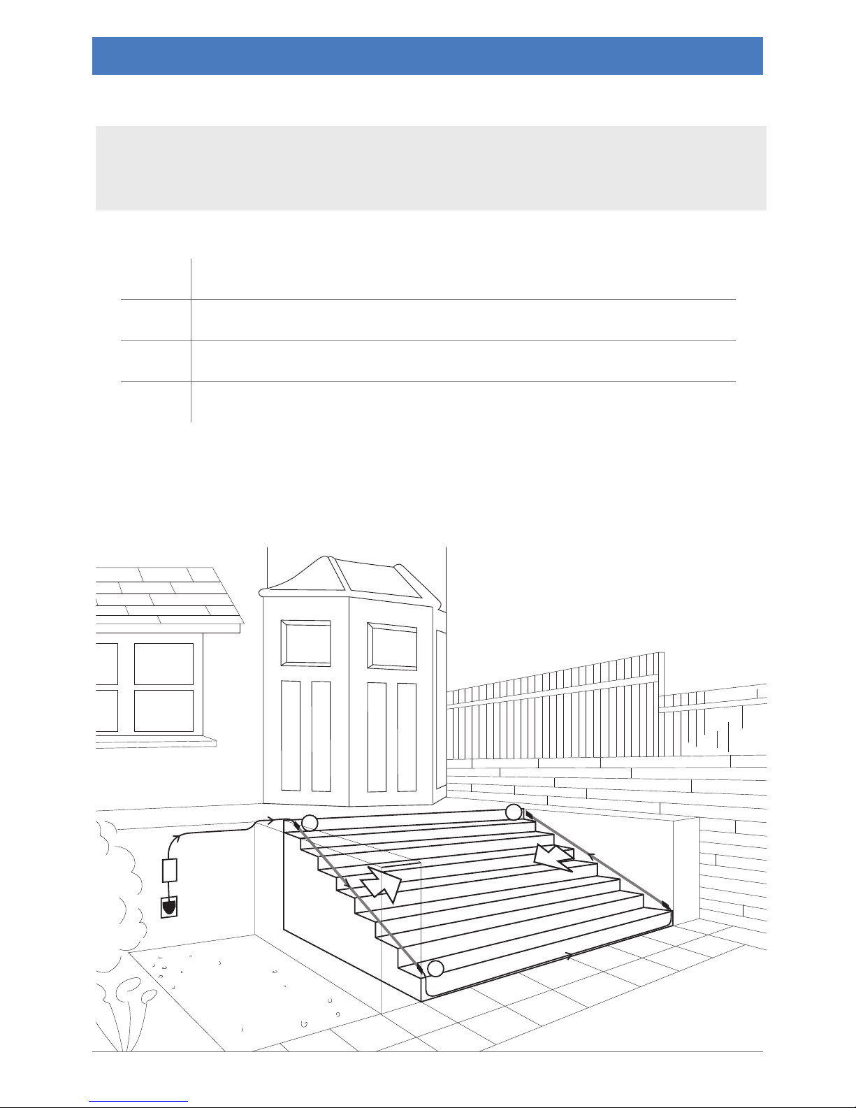
Possible Applications
In this scenario, the power supply is mounted well above the ground so it cannot be submerged in water.
The following chart lists the components used for this scenario.
Outdoor Stairs
E
End Cap
J
Jumper Cable
P
PS-Link Connector
PS
Power Supply
PS
P
J
E
Components
10 cabled.optiled.com
Page 11
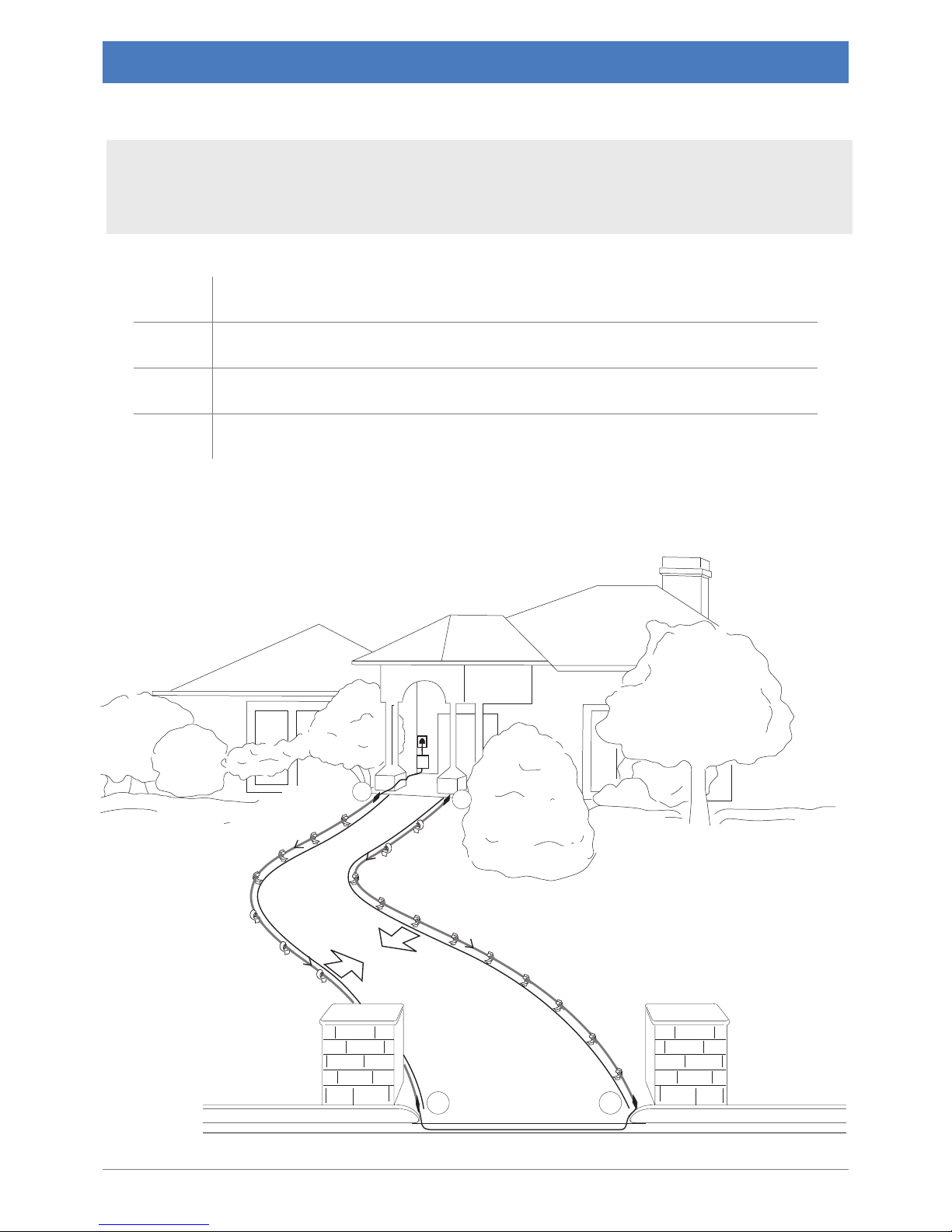
Possible Applications
In this scenario, we have used directional Garden Stakes to mount and angle the CabLED to shine the
light where it is needed, on the path. The power supply is mounted well above the ground so it cannot be
submerged in water. The following chart lists the components used for this scenario.
Walkways
E
End Cap
J
Jumper Cable
P
PS-Link Connector
PS
Power Supply
J J
PS
P
E
Components
cabled.optiled.com 11
Page 12
Plan Your
Project
All CabLED components are rated IP65 and are designed for both
indoor and outdoor use.
Decide whether to use Warm or Cool White CabLED or a combination
of both colors.
Measure the length of each section, rounded o to the nearest 7.09
inch (18cm) interval to determine how much CabLED you will need.
Do NOT cut the CabLED or push the connectors together before you
are ready to install.
Power
Refer to the power supply chart to determine correct power supply.
NOTE: Using an insucient power supply will not light the system to its
full potential or may cause it to icker.
Connectors
Measure each section and adjust your project to determine the
connectors you will use. Each connector has been designed for a
specic purpose, but you may have a few choices for your particular
needs. Use the "Component Layout" section for an overview of the
connectors and how they can be used.
Installation
Follow the instructions carefully when cutting CabLED and attaching
the connectors.
Test your installation before mounting.
Mounting
Use one of the ve mounting solutions.
Tips
Use the Trouble Shooting section when you have problems or contact
our Customer Service Department.
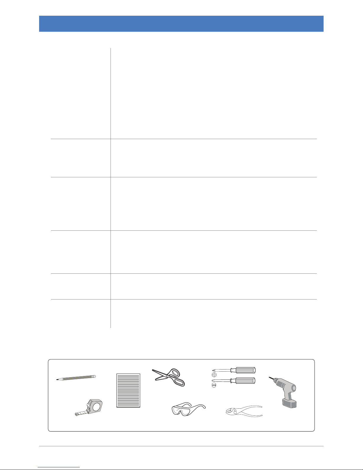
Safety Goggles PliersTape Measure
2
1
Pencil Scissors
Note Pad
Screw Drivers
Power Drill
Design Guidelines
12 cabled.optiled.com
Tools Needed
Page 13
J
OR
AC Outlet
Power
Supply
P
L
T
J
E
E
E
I
U
E
X
P
P
P
P
E
E
E
E
S
or
E
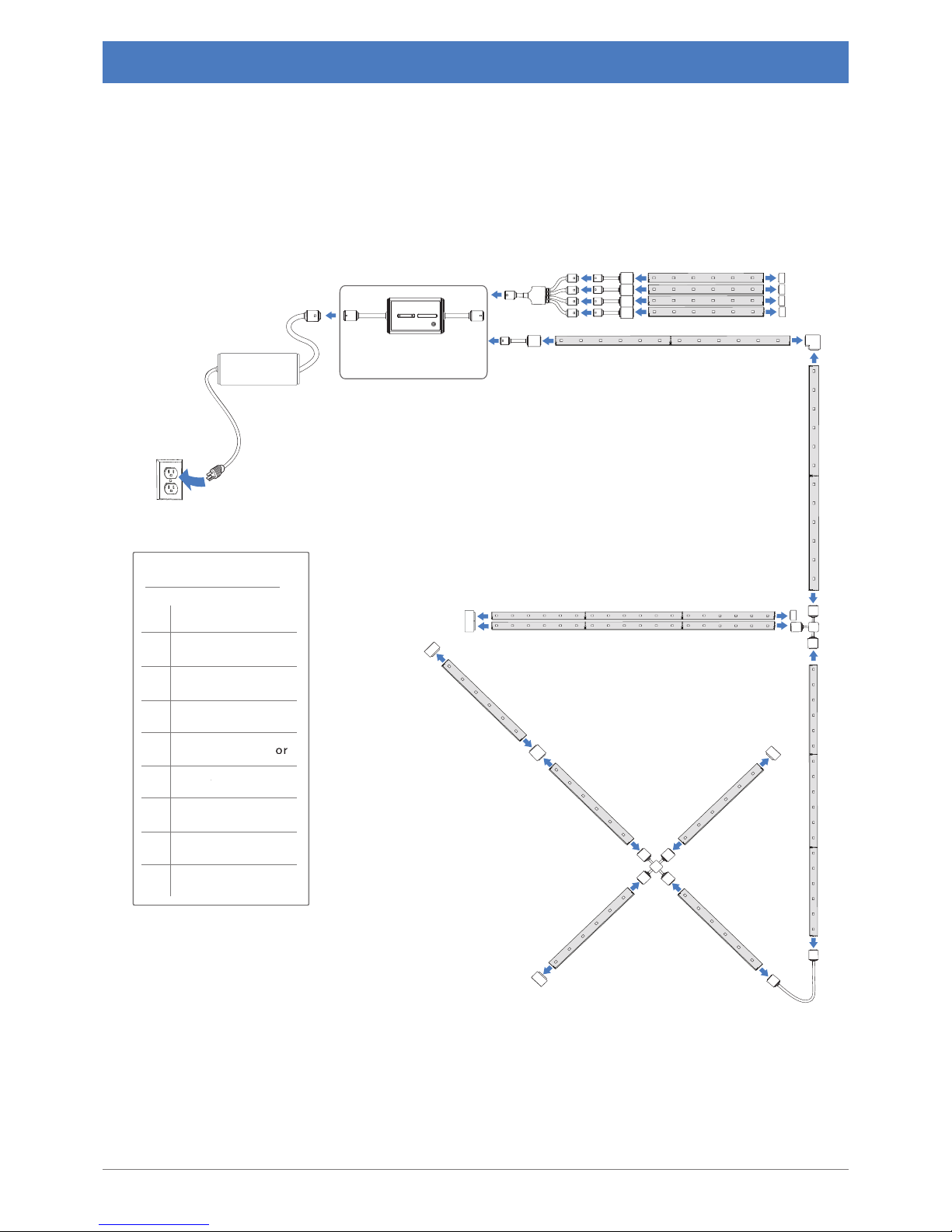
End C ap
I
I-C onnector
J
Jumper C able
L
L-C onnec tor
P
PS-Link Connect
S
Wayower
Split
ter
T
T-C onnec tor
U
U- Connector
X
X-C onnec tor
Connectors
Optional Accessories
Inline ON/OFF
Dimmer Switch
CabLED™ Component Layout
cabled.optiled.com
13
This diagram illustrates possible layouts for the CabLED 8000 Series. Refer to the Component
Overview for additional information.
Page 14
Model Name/Number Description
Cool White (6500K)
4037060105
The Cool White (6500K) LED strip, a bright, bluish
white, is often used for task lighting. Each strip
is 164 feet (50m) long and may be cut every 7.09
inches (18cm).
Warm White (3500K)
4037050105
The Warm White (3500K) LED strip, a yellowish
white, is commonly used in living areas. Each strip
is 164 feet (50m) long and may be cut every 7.09
inches (18cm).
Region/Plug Model Name/Number Description
US
18 Watt 24V Power Supply
5428101817
for CabLED strip
feet (4.5m)
30 Watt 24V Power Supply
5 42 910 3017
for CabLED strip
feet (7.5m)
60 Watt 24V Power Supply
5430106017
for CabLED strip
feet (15m)
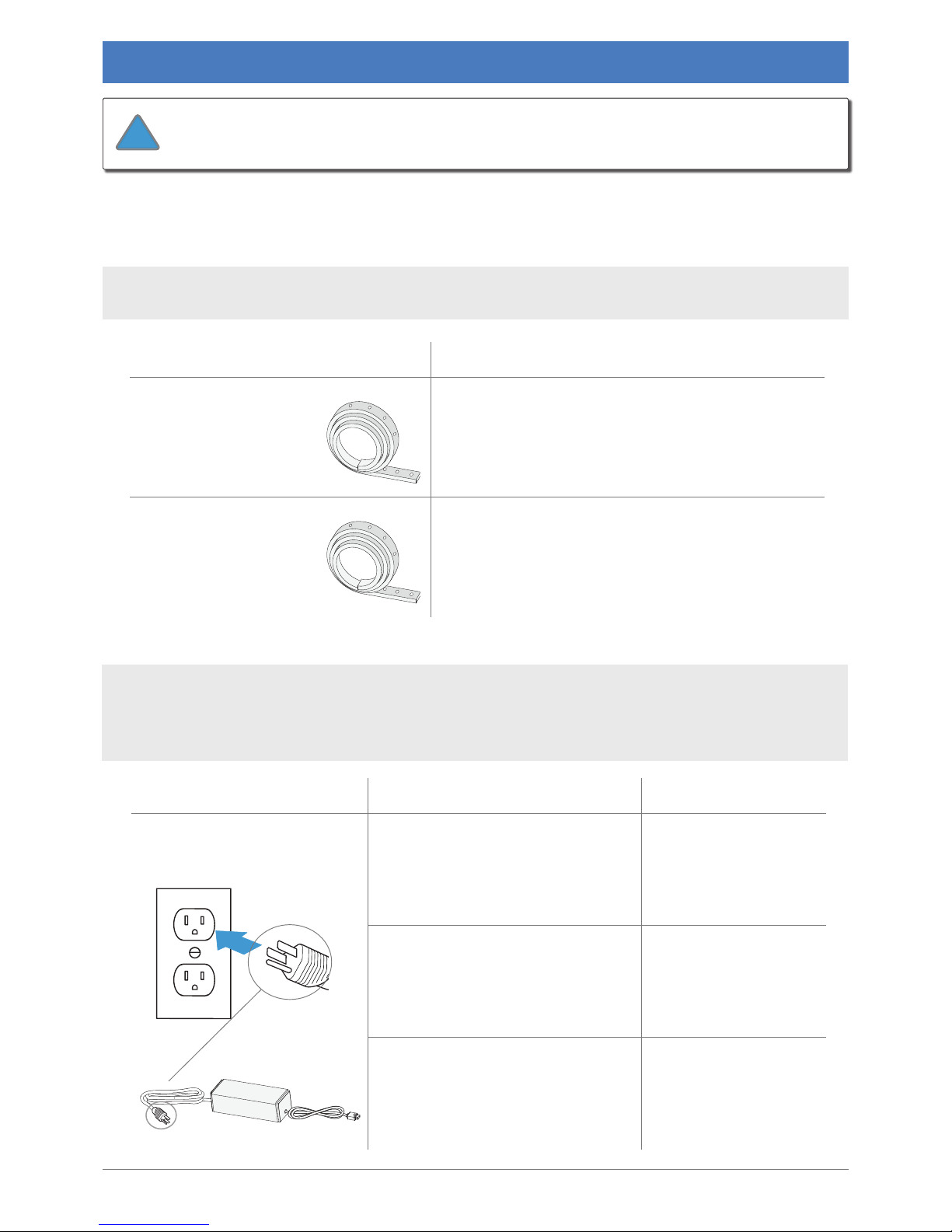
CabLED™ Component Overview
The exible LED strip uses CREE High Brightness LED lights set every inch and can be cut every
7.09 inches (18cm).
available for installations worldwide. The available power supplies are separated by suitable plugs
for each region. After identifying the correct region, determine the length of CabLED strip needed
to select the correct power supply for each installation.
14
cabled.optiled.com
CabLED™ Strip
CabLED 8000 Series consists of the following four components, which may be combined to
customize each application:
The CabLED 8000 system is designed to work ONLY with the
substitute other products as they may damage your system.
!
Power Supplies
Page 15
Model Name/Number Description
4 Way Power Splitter
6401403905
Connects four CabLED strips to one power
supply. Install between power supply and four PSLink Connectors.
End Cap
6401400805
Used in ALL installations.
Protects end of CabLED strip that is not
connected to a connector.
I-Connector
6401400205
Connects two lengths of CabLED strips in a
straight line. Use to extend a length of CabLED
strip.
L-Connector
6401400605
Connects two CabLED strips at a right angle.
PS-Link Connector
64 01400105
Used in ALL installations.
Connects CabLED strip to power supply.
T-Connector
64 01401705
Connects three CabLED strips in a exible T shape.
U-Connector
6401400305
Connects two CabLED strips parallel to each other
for twice the brightness or a balance of warm and
cool colors.
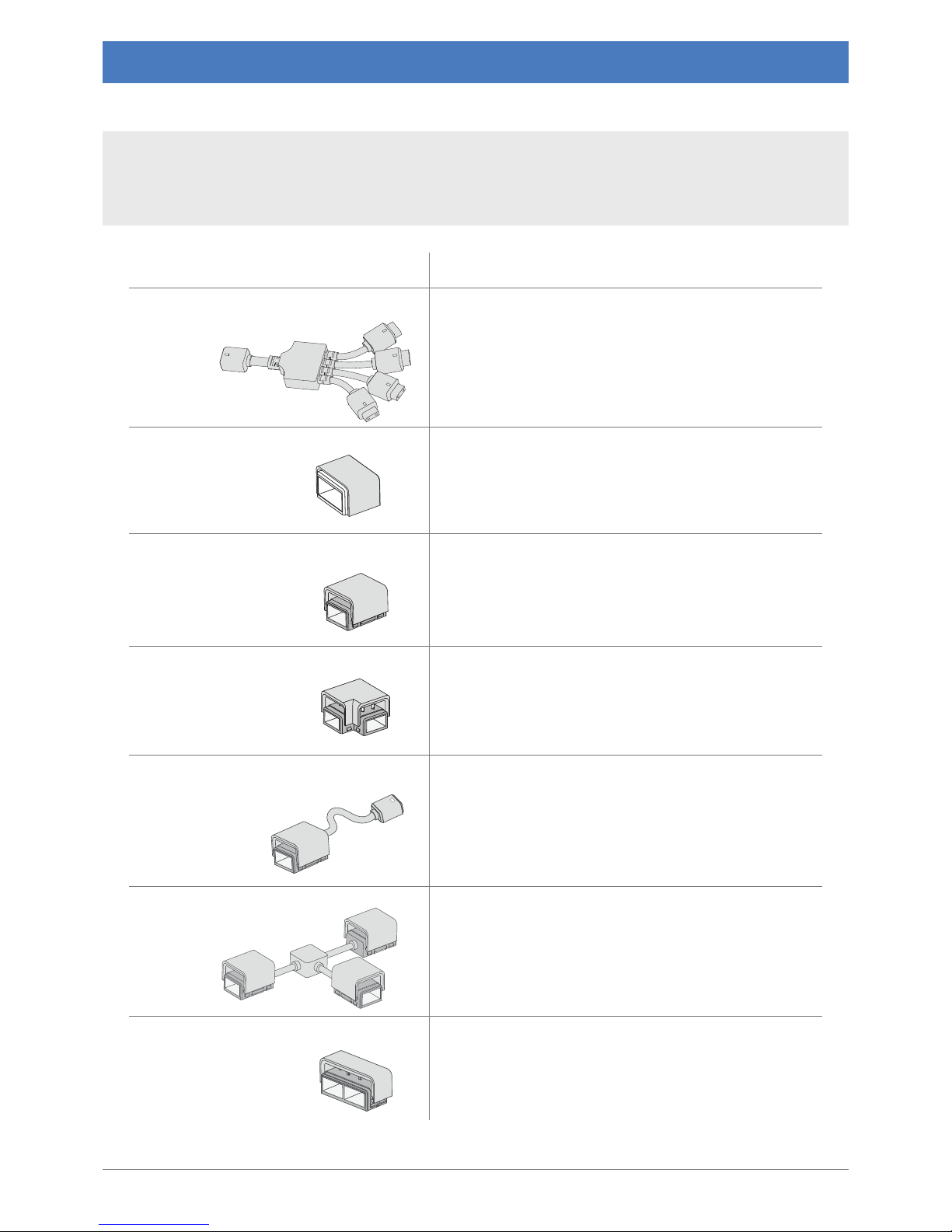
CabLED™ Component Overview
A variety of connectors are designed for specic uses in dierent installations. Connectors are
used to attach sections of LED strip together at various angles and connect the strip to the power
supply. Of the available connectors, the PS-Link Connector and End Cap are required for every
installation. All connectors are rated IP65 for use indoors or outdoors.
cabled.optiled.com 15
Connectors
Page 16
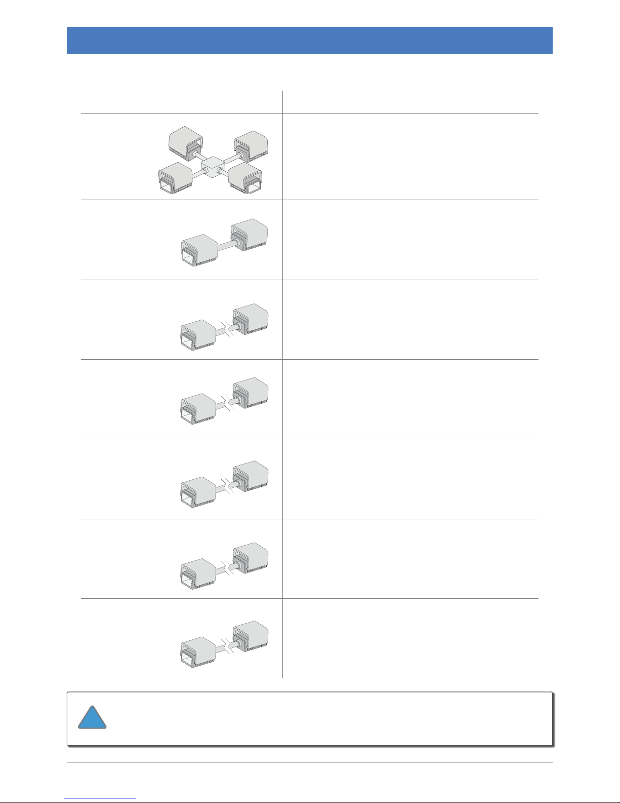
Model Name/Number Description
X-Connector
64 01401805
Connects four CabLED strips at exible right
angles.
2" Jumper Cable
6401402605
Connects two CabLED strips with a 2 inch (5cm)
exible cable.
4" Jumper Cable
6401400905
Connects two CabLED strips with a 4 inch (10cm)
exible cable.
6" Jumper Cable
6401400705
Connects two CabLED strips with a 6 inch (15cm)
exible cable.
12" Jumper Cable
64 01401005
Connects two CabLED strips with a 12 inch (31cm)
exible cable.
24" Jumper Cable
64 01401105
Connects two CabLED strips with a 24 inch (61cm)
exible cable.
40" Jumper Cable
6401402705
Connects two CabLED strips with a 40 inch (101cm)
exible cable.
CabLED™ Component Overview
16
cabled.optiled.com
Connectors (Continued)
The connectors consist of two parts, a top and bottom, which are
you are ready to install.
!
Page 17
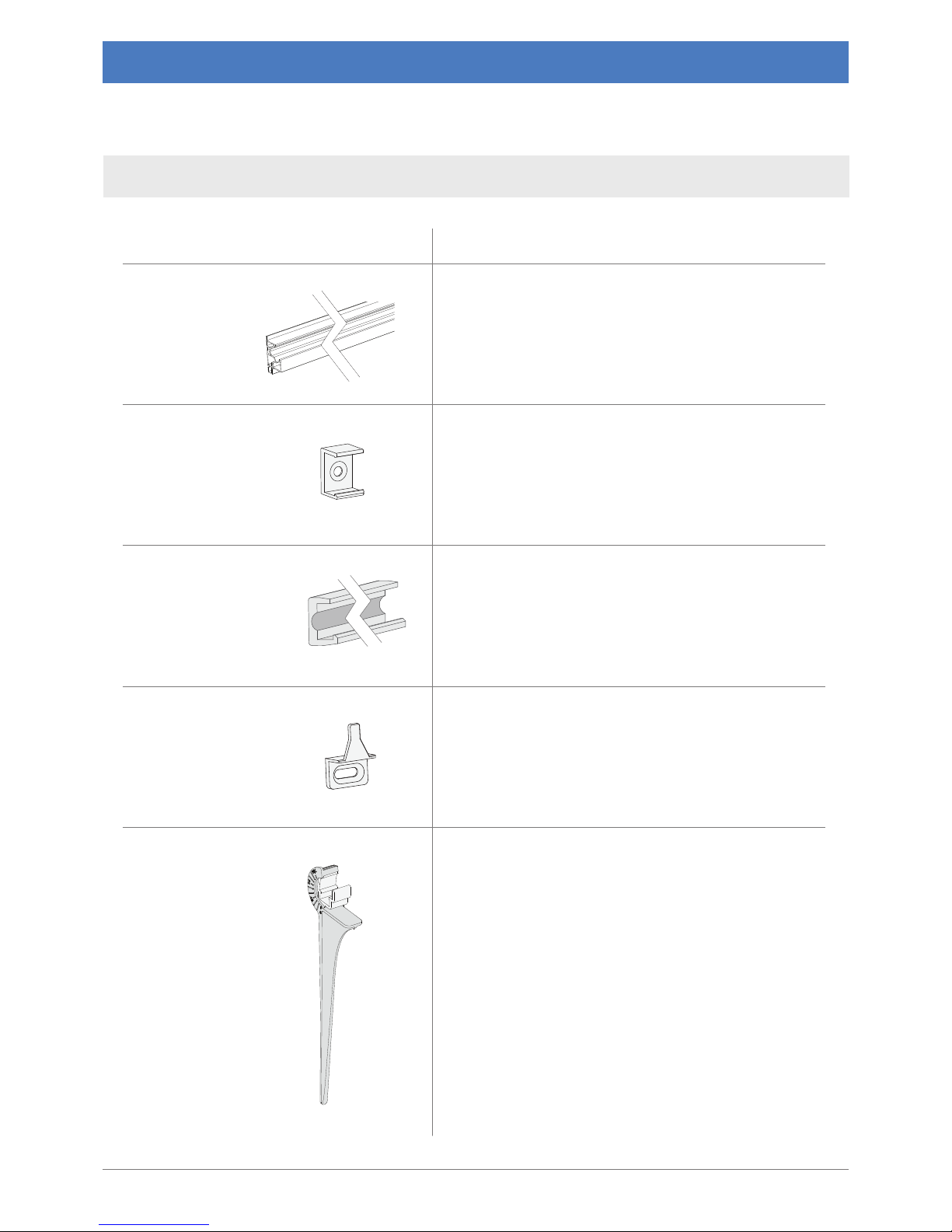
Model Name/Number Description
Angle Channeling
6401402905
Angle Channeling ts into the corner of two
surfaces and directs the light at a 30 degree
angle. You may install it so the light points up or
down. CabLED strip snaps securely into Angle
Channeling that runs the length of the installation.
Channel Bracket
64 01500105
Used in most applications. It installs easily with one
screw and is barely visible after CabLED strip is
snapped into place.
Channeling
6401402805
CabLED strip lies ush and snaps securely into
Channeling that runs the length of the installation.
Edge Bracket
6 4015 00 30 5
Use for ush mount installations such as along a
baseboard. Suitable for use in high trac areas.
Garden Stake
6401403005
Use for outdoor ground installations. Holds the
CabLED above ground so it will not be submerged
in water and adjusts to direct the angle of
light from 0 to 135 degrees. May be used with
Channeling.
CabLED™ Component Overview
A choice of ve types of mounting options are available.
cabled.optiled.com 17
Mounting Options
Page 18
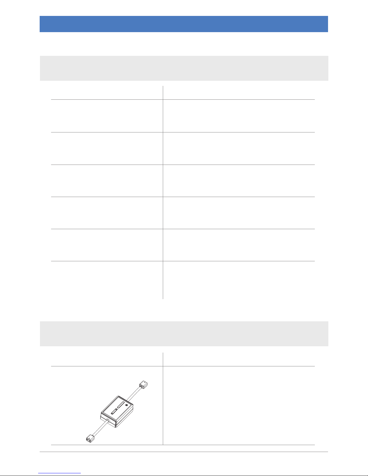
Model Name/Number
Description
System 4.5 CW
C8K-18-CW
This kit includes 14.7 feet (4.5m) Cool White
CabLED strip, an 18W power supply, PS-Link
Connector, End Cap and 15 Channel Brackets.
System 7.5 CW
C8K-30- CW
This kit includes 24.6 feet (7.5m) CabLED Cool
White strip, a 30W power supply, PS-Link
Connector, End Cap and 25 Channel Brackets.
System 15 CW
C8K-60-CW
This kit includes 49.2 feet (15m) Cool White
CabLED strip, a 60W power supply, PS-Link
Connector, End Cap and 50 Channel Brackets.
System 4.5 WW
C8K-18-WW
This kit includes 14.7 feet (4.5m) Warm White
CabLED strip, an 18W power supply, PS-Link
Connector, End Cap and 15 Channel Brackets.
System 7.5 WW
C8K-30-WW
This kit includes 24.6 feet (7.5m) CabLED Warm
White strip, a 30W power supply, PS-Link
Connector, End Cap and 25 Channel Brackets.
System 15 WW
C8K-60-WW
This kit includes 49.2 feet (15m) Warm White
CabLED strip, a 60W power supply, PS-Link
Connector, End Cap and 50 Channel Brackets.
Model Name/Number Description
Inline On/O Dimmer Switch
6401403105
Connects to PS-Link Connector. Oers full dimming
range, fades the CabLED system on and o at last
selected dimming level.
CabLED™ Component Overview
Each of the DIY (Do It Yourself) kits include a PS-Link Connector, End Cap, Channel Brackets and a
power supply suitable for the length of CabLED strip.
18 cabled.optiled.com
DIY CabLED™ System Kits
Accessories
Four IP65 rated accessories are available to enhance your system for either indoor or outdoor use. The RF
Light/Motion Sensor and RF Remote Dimmer require at least one RF Receiver to function.
Page 19
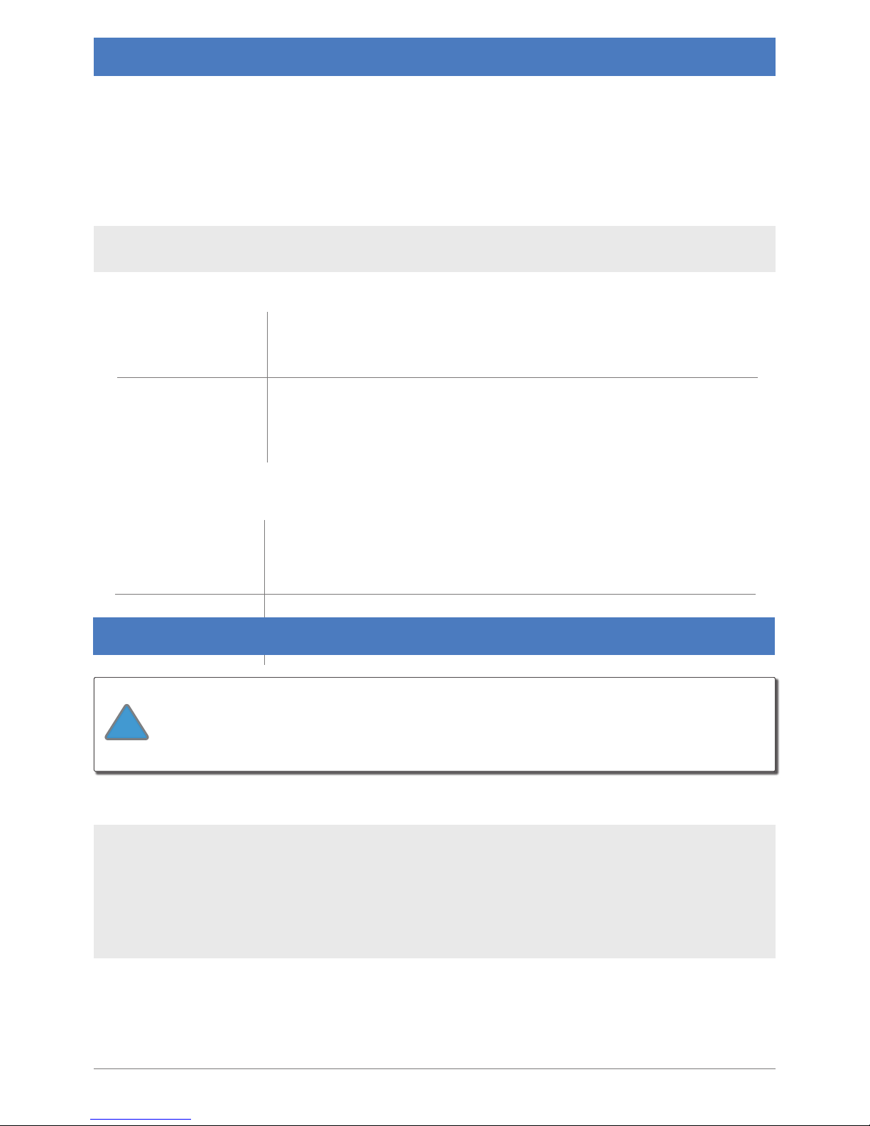
Warm White
(3500K)
A yellowish white more commonly used in living spaces because it is attering
to skin tones. It is often paired with décor dominated by wood tones and
warm colors and is also popular outdoors for general garden/plant lighting.
Cool White
(6500K)
A bright, bluish, white generally used for lighting areas where seeing well is
essential because it produces higher contrast. These include some counter
areas in kitchens, reading lamps, closets and entry ways and is also popular for
outdoor security lighting and walkways.
Inline On/O
Dimmer Switch
The Inline On/O Dimmer Switch is designed to be mounted next to the
CabLED system, providing easy access to full dimming range and power on/o
function. Use when the system is connected to an AC outlet not controlled by
an on/o or dimmer switch.
Step 1: Plan Installation
Step 2: Prepare for Installation
cabled.optiled.com
19
Plan Your Project
The 8000 series oers great exibility so when you are designing your own projects, it is very important
to plan each installation thoroughly before you begin. Begin planning your own installation by
considering the following:
Warm White or Cool White?
The Accessory to be used
What is the Purpose of Your Project?
Think about what you want to accomplish in order to determine the best CabLED color and
installation method to use.
2.1 Determine Components Needed
the accessories you will use. It's time to map out the installation to determine everything else you will need.
Helpful Tips
Adjust your layout plan.
After measuring each section, determine the best solution for the whole
As you are measuring, draw you plan on paper as well.
This will help you see your options and
The CabLED strip may ONLY be cut every 7.09 inches (18cm),
your layout to use the nearest cut line marked on the strip.
!
Page 20
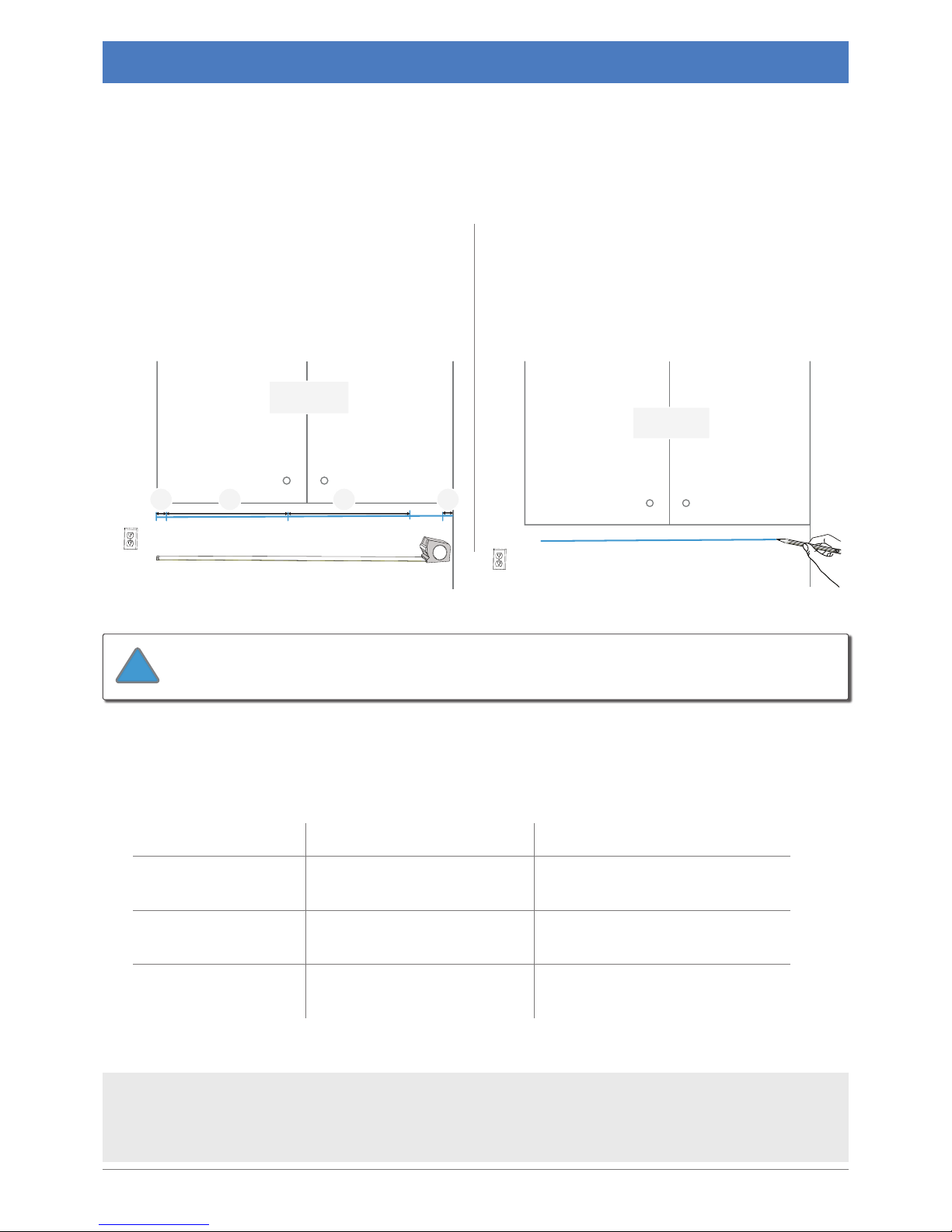
Voltage-VDC Length of CabLED Appropriate Power Supply
24V
24.6 feet (7.5m)
30 Watt 24V Power Supply
24V
49.2 feet (15m)
60 Watt 24V Power Supply
Section 1
Measure to the nearest 7.09” (18cm)
Allow ½” (1.3cm) on each side
½”
½”
7.09” 7.09”
Section 1
Center maximum length
Mark area
Step 2: Prepare for Installation
20
cabled.optiled.com
2.2 Measure and Mark the Area
away from areas where it can be submerged in water and at least one foot above the ground if
A
Measure carefully.
The CabLED strip
and requires a half inch (1.3cm) on either
side of the nal length to allow for the
connectors.
B
Center the CabLED strip in each
section. After determining the maximum
Place power supply near outlet and o the ground so there is no
chance of it being submerged in water.
!
2.3 Select Power Supply
Add up the amount of CabLED in each color to give you the total amount required. Using the
following chart select the power supply equal to or greater than your total length so the LEDs will
The power supplies are available with dierent plugs for various regions worldwide.
When determining the correct model number for your installation, check the region as well
as the strength.
Page 21
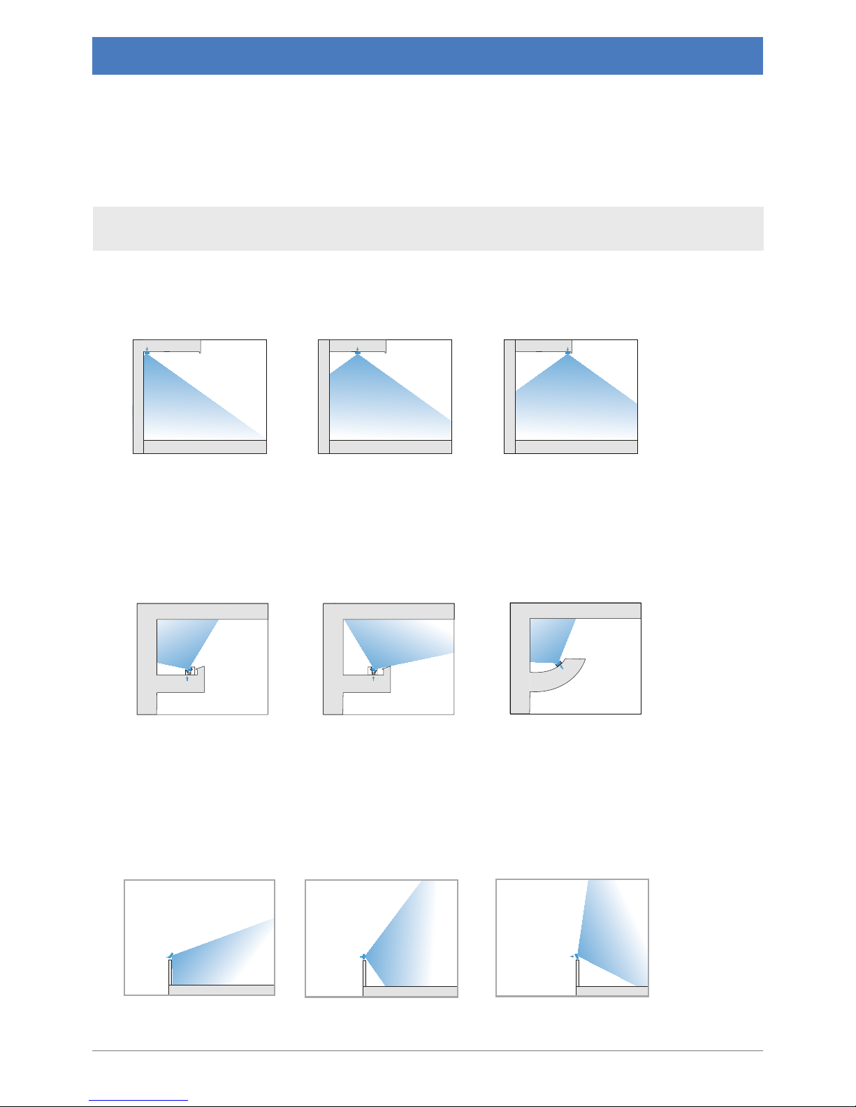
Front Mount
CabLED
Center Mount
CabLED
Back Mount
CabLED
Angled Down
CabLED
(135 degrees)
Angled Out
CabLED
(90 degrees)
Angled Up
CabLED
(45 degrees)
Curved Cove
CabLED
CabLED
Cove Angled Out
CabLED
Cove Angled Back
Step 2: Prepare for Installation
cabled.optiled.com 21
2.4 Mounting Options
When installing the CabLED strip, select one of the six mounting solutions designed for the
8000 Series. The number of brackets or length of channeling depends upon the total quantity of
CabLED in the installation. Plan on using a bracket next to each connector in all sections and then
spaced evenly between 12 to 16 inches (31 to 41cm) apart.
Under Cabinets
When mounting under cabinets, position CabLED strip to get the desired lighting eect.
Cove Lighting
When utilized for cove lighting, position CabLED so it indirectly lights the area.
Path Lighting
When mounting along paths, use the Garden Stake and adjust light at an angle. Use with
Channeling for additional support.
NOTE: For best eect, mount CabLED at least 1.5 inches (4cm) away from the wall.
Mounting Options: Garden Stake with or without Channelling
Mounting Options: Channel Bracket or Channeling
Mounting Options: Angle Channeling or Channeling
Page 22
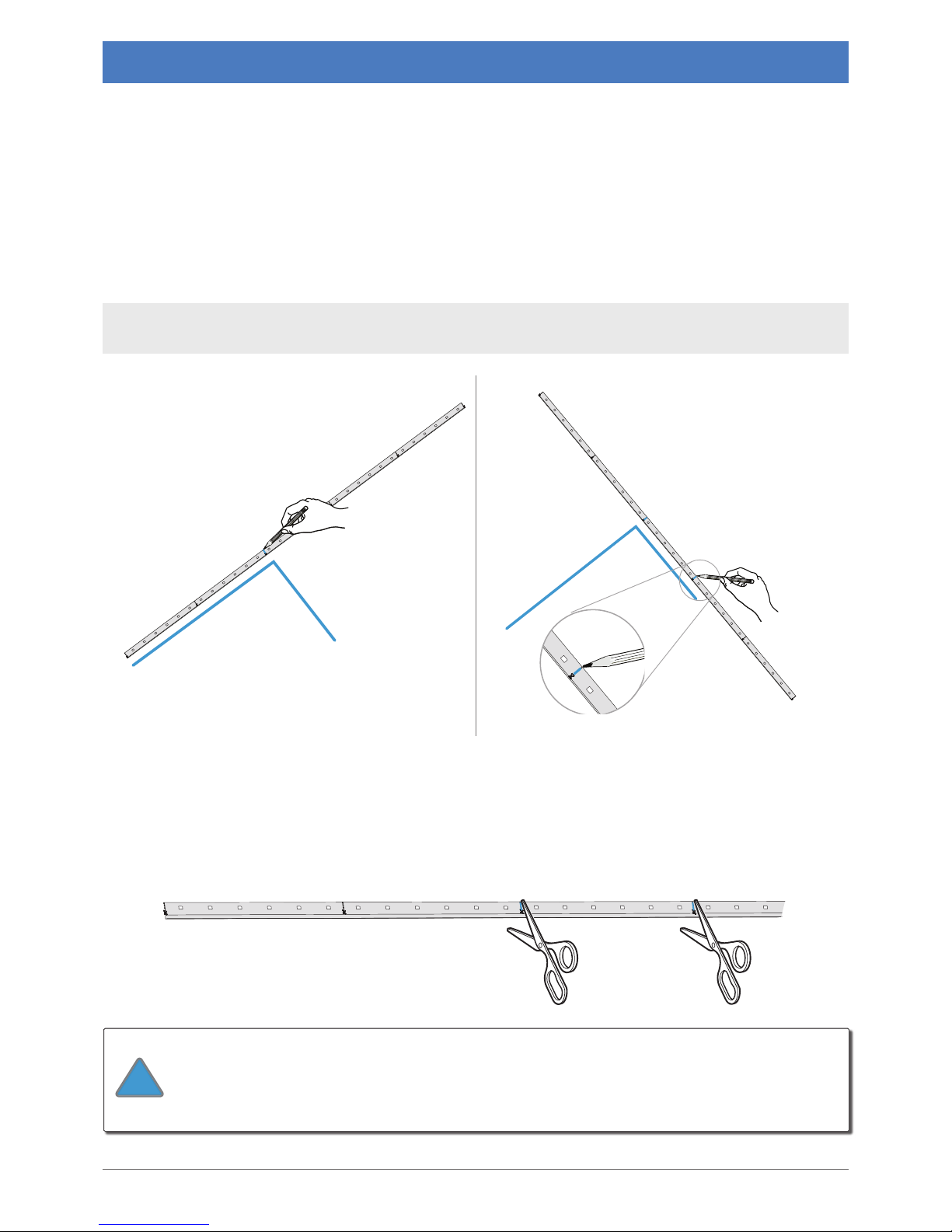
cutting point
one
cutting point
one
cutting point
two
cutting point
one
cutting point
two
Step 3: Begin Installation
22
cabled.optiled.com
3.1 Measure, Mark and Cut CabLED™
it is important to double check before you cut each strip.
3.2 Mark CabLED™
CabLED can ONLY be cut every 7.09 inches (18cm) and must be cut EXACTLY on the cut line.
strip. Repeat for each section.
3.3 Cut CabLED™
If there is a large discrepancy in your measurements, make sure you have selected
the correct components to complete your installation.
A B
The CabLED strip may ONLY be cut every 7.09 inches (18cm),
your layout to use the nearest cut line marked on the strip.
!
Page 23
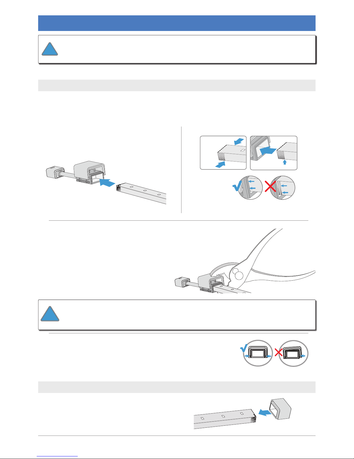
slide until
all ridges are covered
look for ridges
on
each
side
of strip
Step 4: Install Connectors
cabled.optiled.com
23
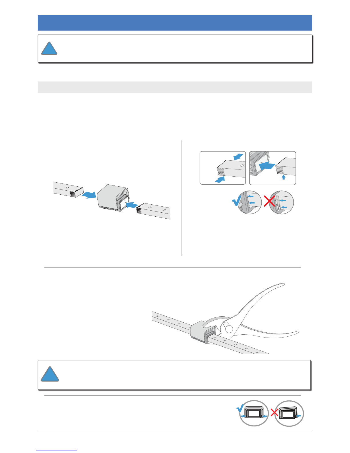
Slide End Cap onto LED strip that will have no connector.
The End Cap protects the strip.
4.1 Install PS-Link Connector
4.2 Install End Cap
The PS-Link Connector attaches the CabLED system to the power supply.
The End Cap protects the side of the CabLED strip not attached to a connector.
A
installed nearest to the power.
With LED side facing up, slide the strip into
the opening in bottom half of the connector
B
Push the strip completely into the connector.
The ridges on each side of the strip will be
covered when the strip is properly installed.
C
Using pliers, apply even pressure to the bottom and top halves of the
connector to push connector together, securing CabLED strip inside.
D
Make sure both sides of the bottom half of the connector snap
into the top half. Gently pull the LED strip to make sure you have
installed it properly.
The connectors consist of two parts, a top and bottom, which are
are ready to install.
!
When using pliers that do not cover the entire surface of the connector, hold
the connector and strip steady so the CabLED strip remains in position. Carefully rotate the
!
Page 24
slide until
all ridges are covered
look for ridges
on
each
side
of strip
Step 4: Install Connectors
24
cabled.optiled.com
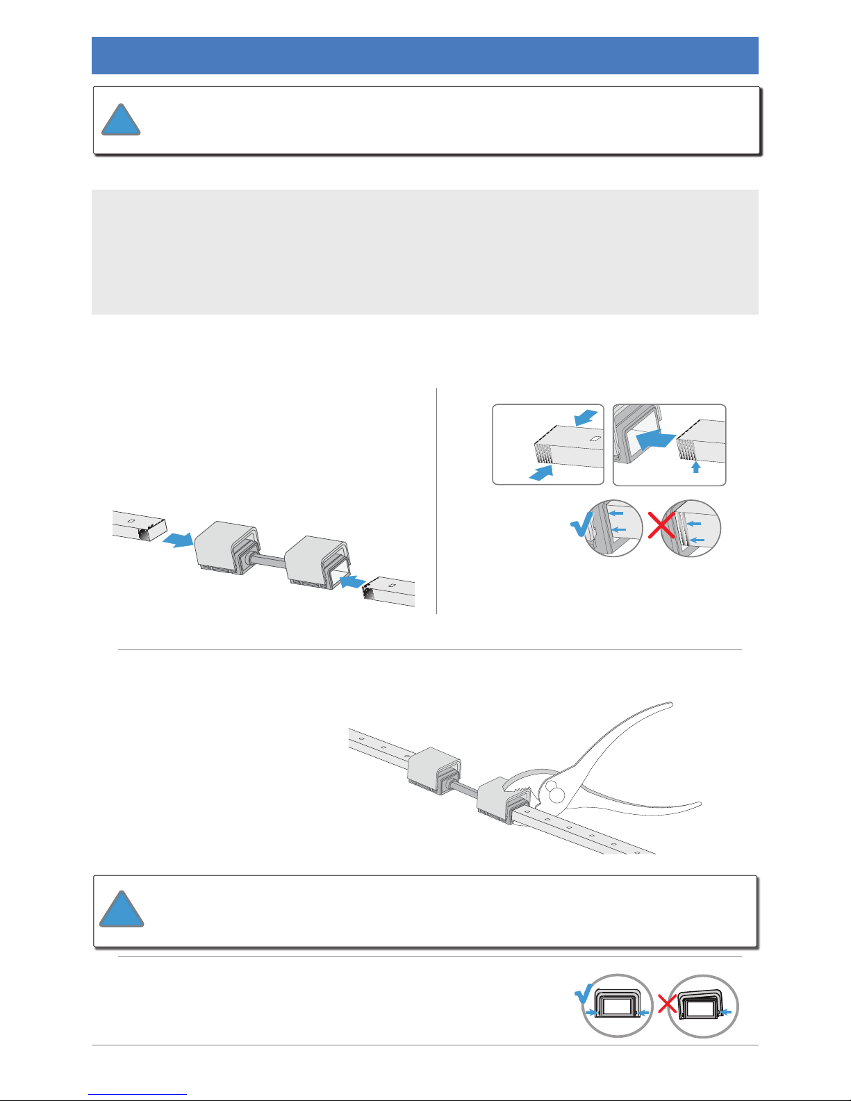
Connects two lengths of CabLED strips in a straight line. Use to add extra length to the main strip.
4.3 Install I-Connector
A
facing up, insert one strip into one side of the
other strip into the other side and push it to
the end.
B
Push the strips completely into the connector.
The ridges on each side of the strip will be
covered when the strip is properly installed.
D
Make sure both sides of the bottom half of the connector snap into
the top half. Gently pull the CabLED strips to make sure you have
installed it properly.
The connectors consist of two parts, a top and bottom, which are
are ready to install.
!
When using pliers that do not cover the entire surface of the connector, hold
the connector and strip steady so the CabLED strip remains in position. Carefully rotate the
!
C
Using pliers, apply even pressure to the bottom and top connector to push
connector together, securing CabLED strips inside.
Page 25
slide until
all ridges are covered
look for ridges
on
each
side
of strip
Step 4: Install Connectors
cabled.optiled.com
25
D
Make sure both sides of the bottom half of the connector snap into
the top half. Gently pull the CabLED strips to make sure you have
installed it properly.
A
Remove the protective piece from both sides
of the Jumper Connector. With LED side
facing up, slide one CabLED strip into the
opening in bottom half of one side of the
connector until it reaches the end. Repeat
with the other CabLED strip in the other side
of the connector.
B
Push the strip completely into the connectors.
The ridges on each side of the strip will be
covered when the strip is properly installed.
The Jumper Cable connects two CabLED strips with a exible cable. They are available with 2",
4”, 6”, 12”, 24” and 40” cables. Use the shorter lengths for connecting two CabLED strips at any
angle, or when the strips do not meet at 90 degree angles after being centered to a section.
The medium lengths are often used for stairs, running strips parallel with each other with space
cabinets with an appliance between them, extending the system behind a larger area.
4.4 Install Jumper Cable
C
Using pliers, apply even pressure to the bottom and top halves of each
connector to push them together, securing the CabLED strips inside.
The connectors consist of two parts, a top and bottom, which are
!
When using pliers that do not cover the entire surface of the connector, hold
the connector and strip steady so the CabLED strip remains in position. Carefully rotate the
!
Page 26
slide until
all ridges are covered
look for ridges
on
each
side
of strip
Step 4: Install Connectors
26
cabled.optiled.com
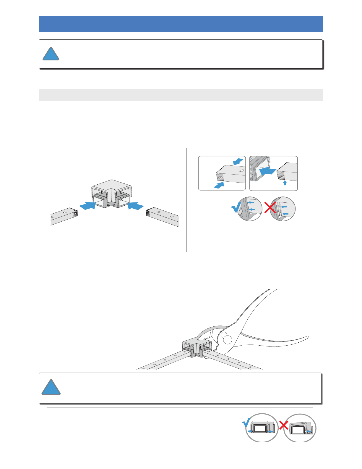
C
Using pliers, apply even pressure to the bottom and top halves of each
connector to push them together, securing the CabLED strips inside.
Connects two CabLED strips at a 90 degree angle to form a corner.
4.5 Install L-Connector
The connectors consist of two parts, a top and bottom, which are
are ready to install.
!
A
facing up, insert one strip into one side of the
other strip into the other side and push it to
the end.
B
Push both strips completely into the
connector. The ridges on each side of the
strip will be covered when the strip is properly
installed.
When using pliers that do not cover the entire surface of the connector, hold the
connector and strip steady so the CabLED strip remains in position. Carefully rotate the pliers and apply
!
D
Make sure both sides of the bottom half of the connector snap into
the top half. Gently pull the CabLED strips to make sure you have
installed them properly.
Page 27
slide until
all ridges are covered
look for ridges
on
each
side
of strip
Step 4: Install Connectors
cabled.optiled.com
27
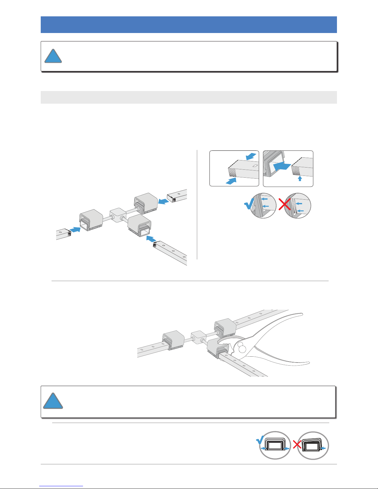
B
Push the strips completely into the connector.
The ridges on each side of the strips will be
covered when the strip is properly installed.
D
Make sure both sides of the bottom half of the connector snap into
the top half. Gently pull the CabLED strips to make sure you have
installed them properly.
4.6 Install T-Connector
Connects three CabLED strips in a exible T shape.
C
Using pliers, apply even pressure to the bottom and top halves of each
connector to push them together, securing the CabLED strips inside.
A
Remove the protective piece from each side
of the T-Connector. With LED side facing
in bottom half of one side of the connector
other CabLED strips in the other sides of the
connector.
The connectors consist of two parts, a top and bottom, which are
are ready to install.
!
When using pliers that do not cover the entire surface of the connector, hold
the connector and strip steady so the CabLED strip remains in position. Carefully rotate the
!
Page 28
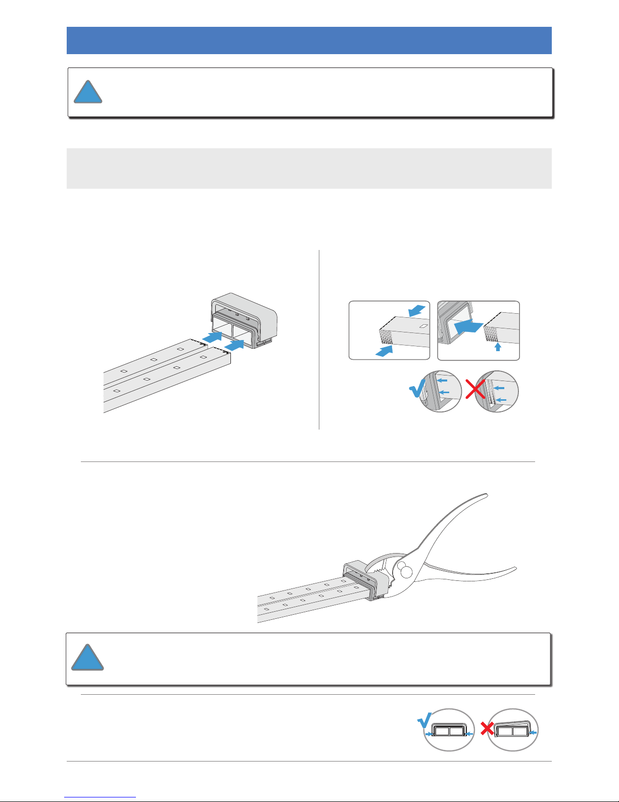
slide until
all ridges are covered
look for ridges
on
each
side
of strip
Step 4: Install Connectors
28
cabled.optiled.com
The connectors consist of two parts, a top and bottom, which are
are ready to install.
!
4.7 Install U-Connector
Connects two CabLED strips parallel with each other for twice the brightness or to achieve a
A
facing up, insert each CabLED strip into the
C
together, securing CabLED strips inside.
B
Push both strips completely into the
connector. The ridges on each side of the
strips will be covered when the strip is
When using pliers that do not cover the entire surface of the connector, hold the
connector and strip steady so the CabLED strip remains in position. Carefully rotate the pliers
and apply pressure to each side of the connector, pushing the top and bottom together.
!
D
Make sure both sides of the bottom half of the connector snap into
the top half. Gently pull the CabLED strips to make sure you have
installed them properly.
Page 29
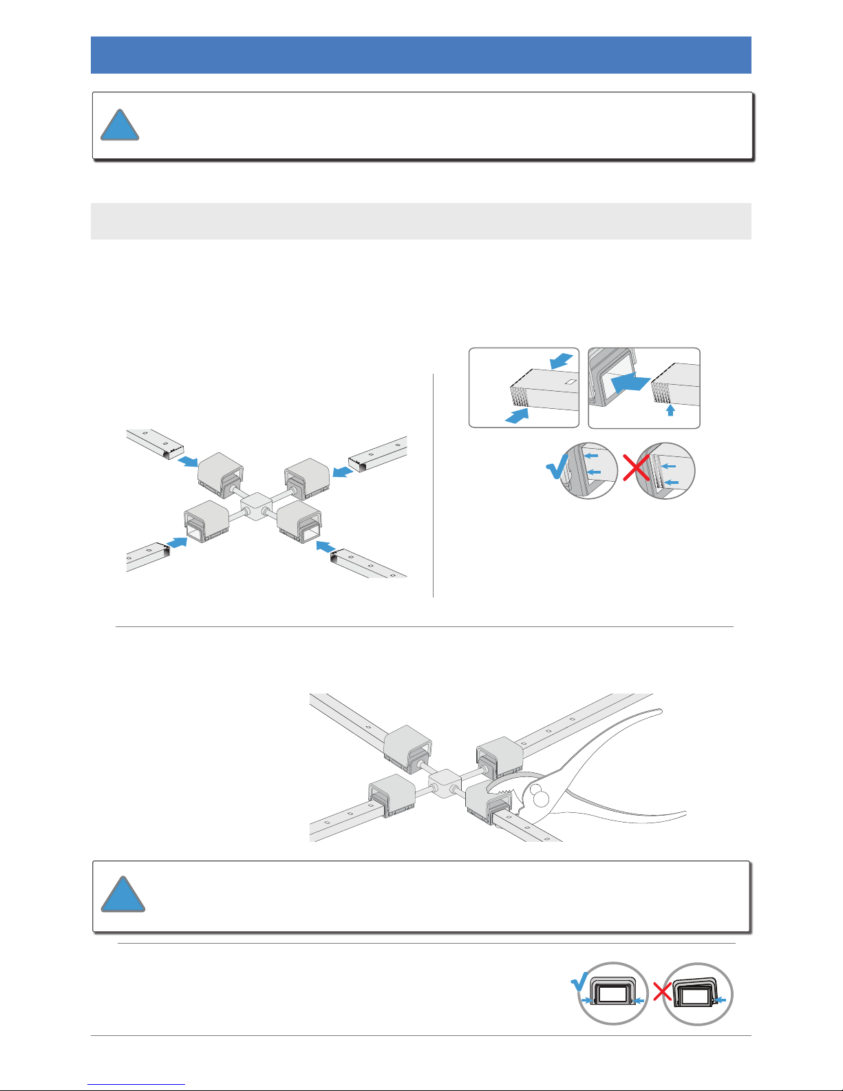
slide until
all ridges are covered
look for ridges
on
each
side
of strip
Step 4: Install Connectors
cabled.optiled.com
29
B
Push the strips completely into the connector.
The ridges on each side of the strips will be
covered when the strip is properly installed.
4.8 Install X-Connector
D
Make sure both sides of the bottom half of the connector snap into
the top half. Gently pull the CabLED strips to make sure you have
installed them properly.
C
Using pliers, apply even pressure to the bottom and top halves of each connector to
A
Remove the protective piece from each side
of the X-Connector. With LED side facing
in bottom half of one side of the connector
other CabLED strips in the other sides of the
connector.
Connects four CabLED strips at exible right angles.
The connectors consist of two parts, a top and bottom, which are
are ready to install.
!
When using pliers that do not cover the entire surface of the connector, hold
the connector and strip steady so the CabLED strip remains in position. Carefully rotate the
!
Page 30
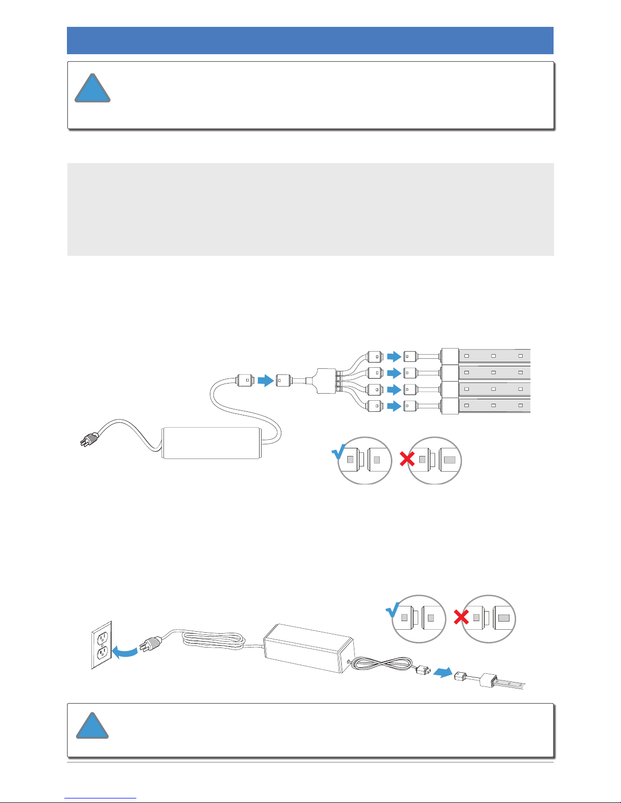
Step 4: Install Connectors
30
cabled.optiled.com
4.9 Install 4 Way Power Splitter
TEST
The 4 Way Power Splitter connects four strips of CabLED to one power supply and ts between
the power supply and the PS-Link Connectors.
Select the power supply according to the combined length of CabLED connected
to the 4 Way Power Splitter. Each of the strips function independently, can be dierent
CabLED strip must not exceed 82 feet (25m).
Splitter ts between the power supply and the PS-Link Connectors.
Connector with the icons on the 4 Way Power Splitter. Match the icons on the power supply with
the icons on the other side of the 4 Way Power Splitter.
Matching the icons, connect the PS-Link Connector to the power supply. Plug the power supply
into the AC outlet. If it works properly, unplug it and continue. If not, see the Troubleshooting
section.
There is only one way to connect the PS-Link Connector to the power
supply. Make certain the icons match before connecting. Connect the power supply
to the PS-Link Connector BEFORE plugging the power supply into the AC outlet.
!
There is only one way to connect the 4 Way Power Splitter to the
connecting. Connect the 4 Way Power Splitter to the PS-Link Connectors and to the
!
Page 31
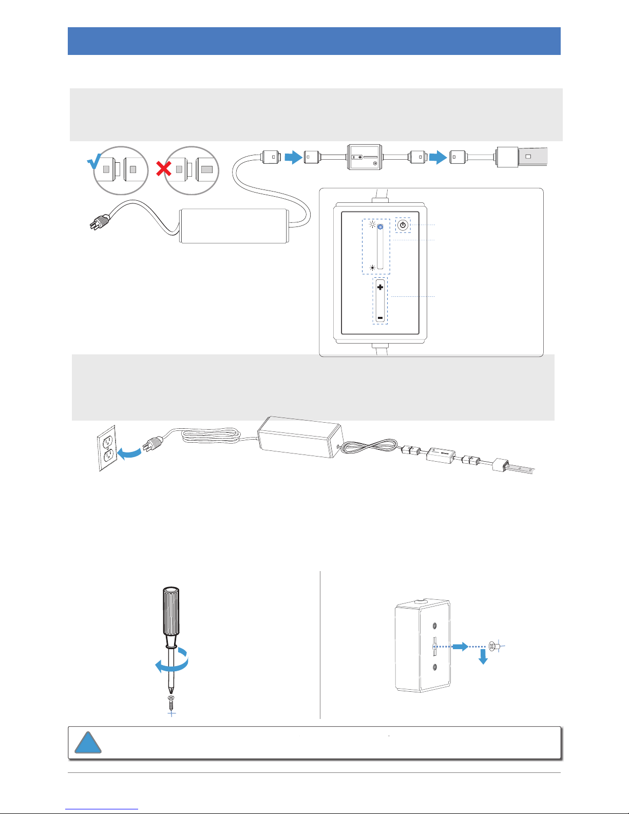
Step 5: Install Connectors
cabled.optiled.com
31
5.1 Install Inline On/O Dimmer Switch
5.2 Mount Inline On/O Dimmer Switch
Test
The Inline On/O Dimmer Switch ts between the PS-Link Connector and the power supply. The Unplug
the power supply from the AC outlet before connecting. Match the icons on the PS-Link . Connector with
the icons on the Inline Dimmer. Connector with the icons on the Inline Dimmer.
Power Button: On/O
Level 5 (max) (shown)
Level 4
Level 3
Level 2
Level 1 (min)
Light Bar Indicator:
+: Increase light level
- : Decrease light level
Dimming Bar:
A
Screw M4 screw partially into surface, leaving
B
Fit
ce
over screw and slide down to mount.
D
c
onnect
fro
ower supply
b
efore
Mo
supply and o the groun
d so ther
e o chanc
e
of water.
!
Page 32
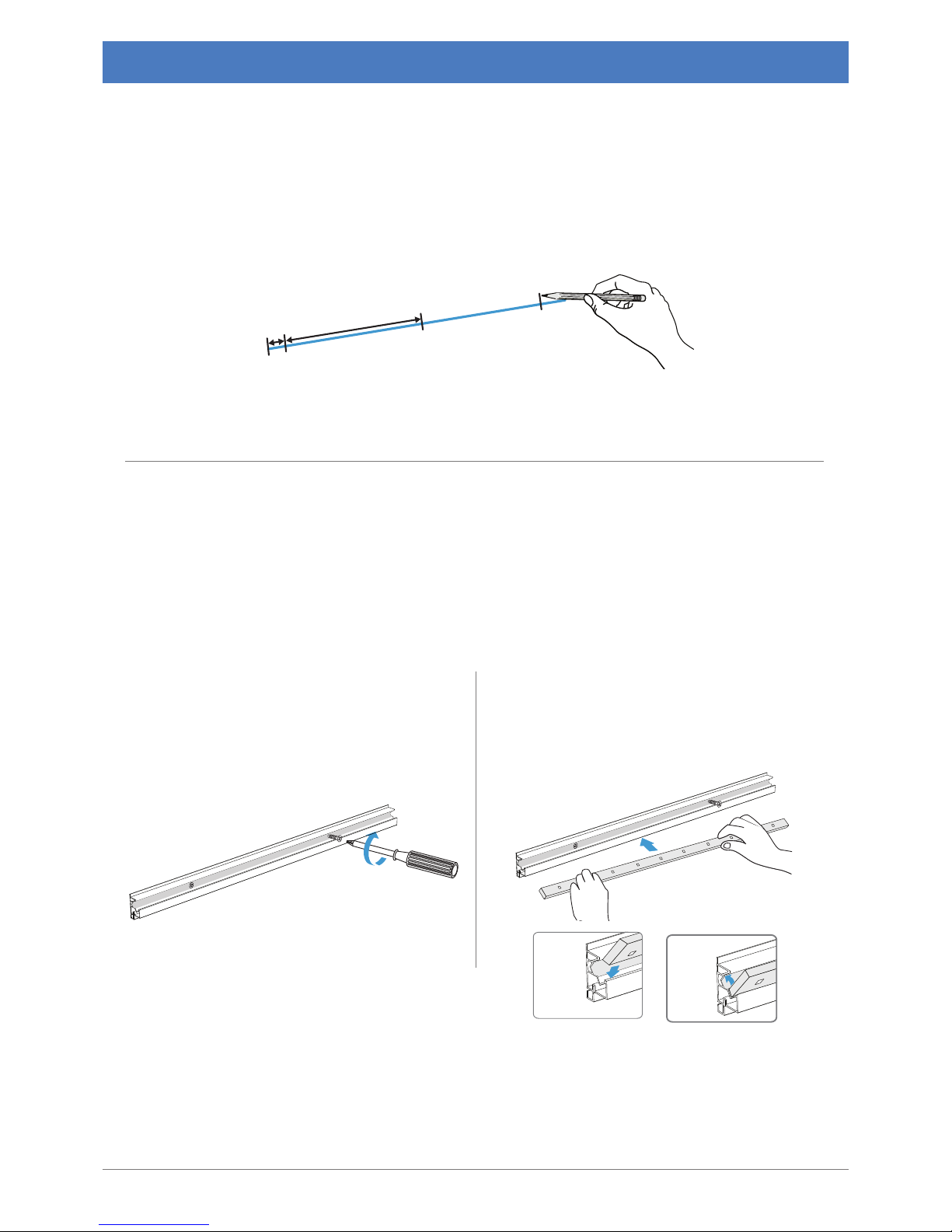
12"-16"
½"
1.3cm
31-41cm
Step 6: Mount CabLED™
32 cabled.optiled.com
6.2 Use One of the Following Five Methods to Mount CabLED™
6.1 Mark Placement for Brackets
When installing the CabLED strip, select one of the six IP65 mounting solutions designed to be
used with the 8000 Series for either indoors or outdoors. Plan on using a bracket next to each
connector on the end of each strip in each section and then spaced evenly between 12 to 16
inches (31-41cm) apart. Allow a half inch to clear each connector.
Install Angle Channeling
Angle Channeling ts into the corner of two surfaces and directs the light at a 30 degree angle.
You may install it so the light points up or down. The example shows the light pointing down.
into
bottom
slide
into
lip
snap
A Determine the desired direction of the light
and hold Angle Channeling against surface.
Secure with screw every 12 to 16 inches (3141cm). Or apply double sided tape on the
bottom of the Angle Channeling.
B Slide CabLED at an angle into the longer side of
the Angle Channelling, and then push down to
snap strip into place.
Page 33
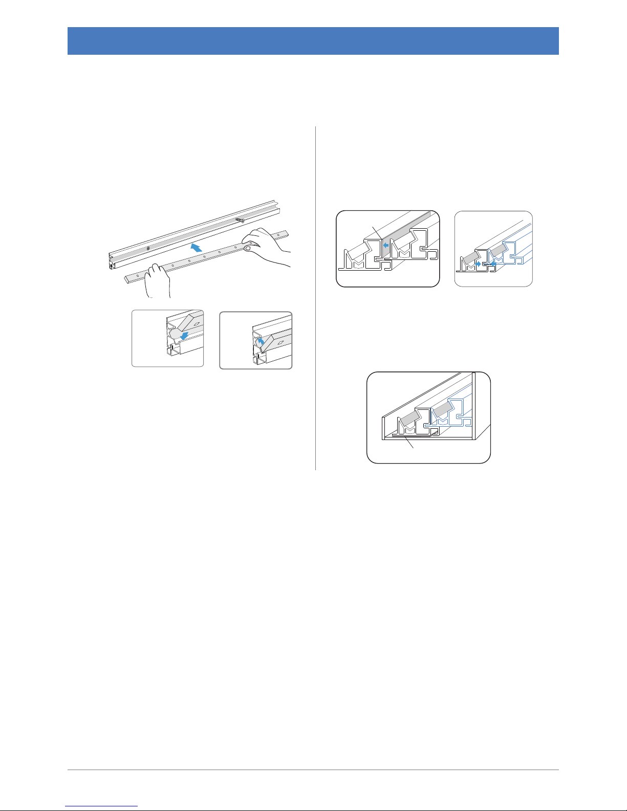
6.2 Use One of the Following Five Methods to Mount CabLED™
cabled.optiled.com 33
into
bottom
slide
into
lip
snap
Double sided tape
Double sided tape
B Apply double sided tape on the back of
one Angle Channeling. Fit the edge of the
Angle Channeling into the slit of the second
Angle Channeling to pair up two CabLEDs
for double the brightness. (note : pairing
maximum of two CabLED is recommended.)
C Apply double sided tape on the bottom
of the rst Angle Channeling. Tape Angle
Channeling onto the cove surface according
to the desired direction of the light.
A Slide CabLED at an angle into the longer
side of the Angle Channeling, and then push
down to snap strip into place. Repeat fot the
second Angle Channeling.
Install Double Angle Channelings
Angle Channeling ts into the corner of two surfaces and directs the light at a 30 degree angle.
You may pair up two Angle Channelings with two CabLEDs for the double brightness.
Page 34
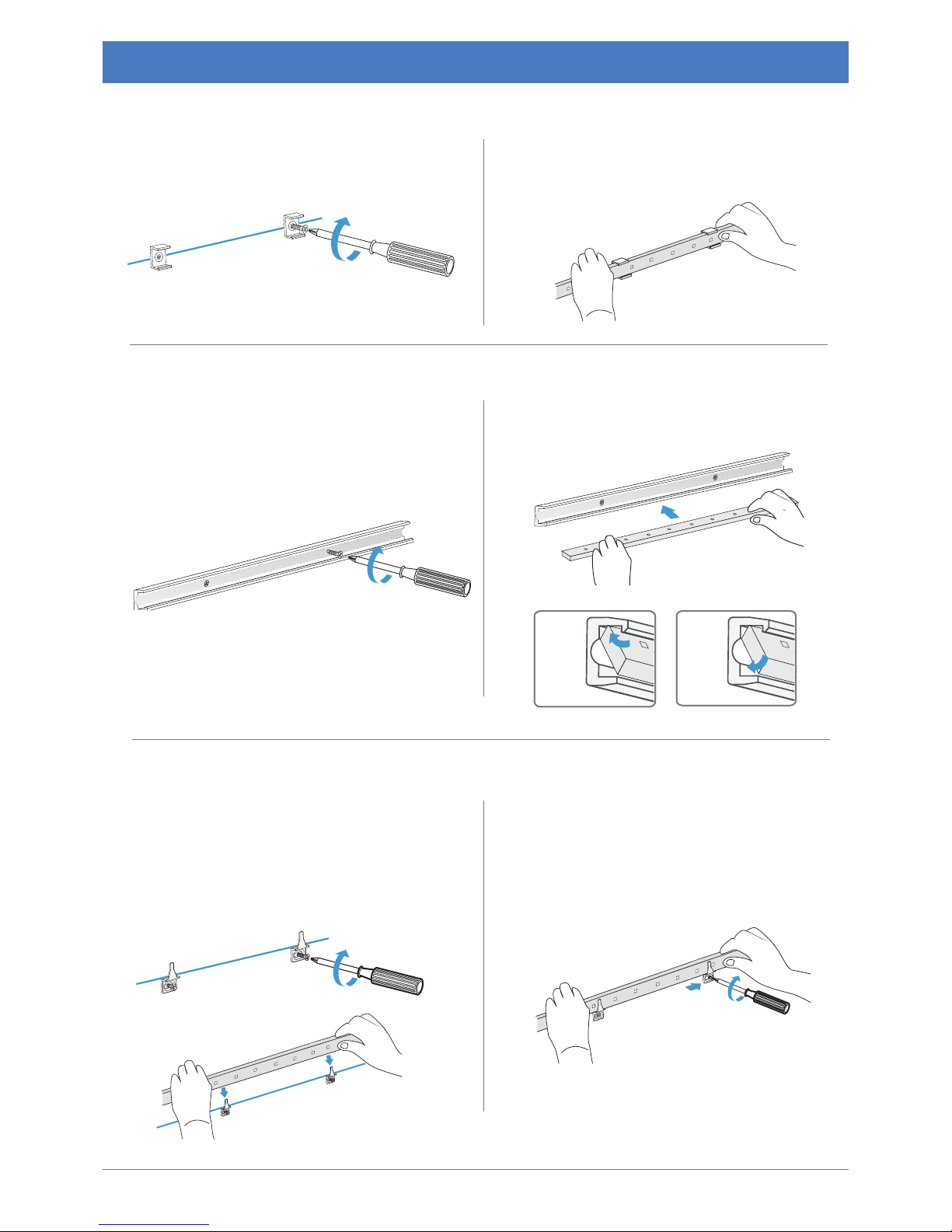
snap
into
lip
snap
into
lip
Step 6: Mount CabLED™
34
cabled.optiled.com
A
installed. Hold Channeling against surface.
Secure with screw every 12 to 16 inches (31-
41cm).
B
Slide CabLED straight into top of Channeling,
and then push down to snap strip into place.
A
Screw Channel Brackets into surface.
B
Starting from PS-Link Connector, press
CabLED strip rmly into each channel bracket.
Make certain strip
A
Screw Edge Brackets partially into surface.
Start from PS-Link Connector. Slide CabLED
it lies at and the bracket doesn't cover the
B
Adjust placement if necessary when
tightening screws.
Install Edge Bracket
Install Channeling
Install Channel Bracket
Page 35
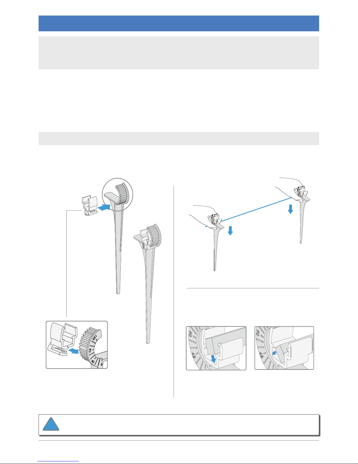
Step 6: Mount CabLED™
cabled.optiled.com
35
B
Push the stakes rmly into the ground spaced
from 12 to 16 inches (31-41cm) apart.
A
Set the angle by tting the mounting clip
into the stand at the desired angle.
C
Insert CabLED strip into one side of bottom
channel and snap into place.
covered when strip is installed. Reposition
stake if necessary.
Install Garden Stake
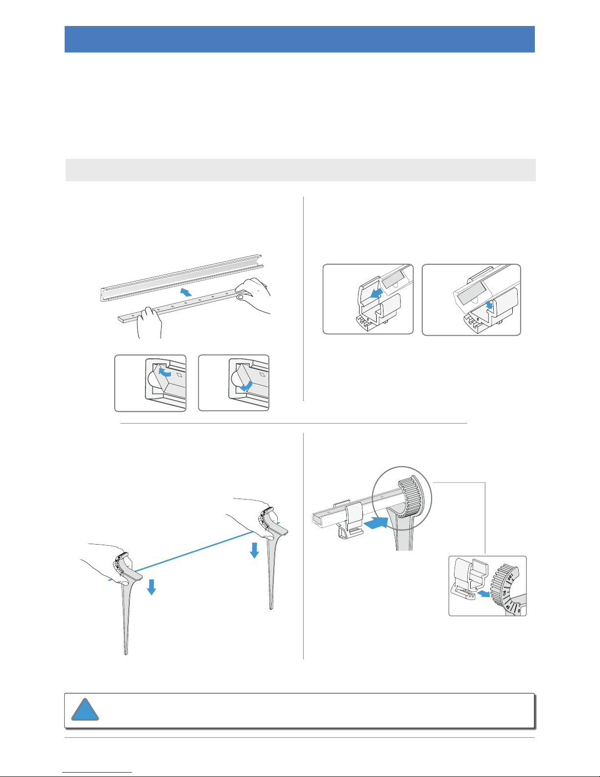
The Garden Stake consists of two pieces, the mounting clip and the stand, which are assembled
to angle the direction of the light between 0 and 135 degrees at 11.25 degree intervals.
The mounting clip, is designed with two cavities. Install the CabLED strip alone in the bottom or
the CabLED strip with the Channeling into the top. Follow the instructions for each method for
the easiest installation.
Use Garden Stakes where CabLED will be installed on the ground
outside. Install so CabLED or connectors will NOT be submerged in water.
Angle marked on
outside stand
The Garden Stakes are two-piece mounts designed to hold the CabLED strips along pathways and
can be set so the light is directed at an angle between 0 and 135 degrees at 11.25 degree intervals.
The mounting clip is designed with two cavities to either hold the strip alone, or for added
support, with the Channeling.
Installation shown at 0 degree angle.
!
Page 36
snap
into
lip
snap
into
lip
slide
into
top
snap
in
place
Step 6: Mount CabLED™
36
cabled.optiled.com
Installation shown at 0 degree angle.
C
Push the stakes rmly into the ground spaced
from 12 to 16 inches (31-41cm) apart.
D
Fit each mounting clip into the stake at the
desired angle.
A
First install the CabLED into the Channeling
Channeling, and then push down to snap
strip rmly and smoothly into Channeling.
B
Install Channeling into upper cavity of
same distance you are installing the stands,
Adjust Channeling if LEDs are blocked by the
stand.
Install Garden Stake With Channeling
The Garden Stake consists of two pieces, the mounting clip and the stand, which are assembled
to angle the direction of the light between 0 and 135 degrees at 11.25 degree intervals.
The mounting clip, is designed with two cavities. Install the CabLED strip alone in the bottom or
the CabLED strip with the Channeling into the top. Follow the instructions for each method for
the easiest installation
Angle marked on
outside stand
Use Garden Stakes where CabLED will be installed on the ground
outside. Install so CabLED or connectors will NOT be submerged in water.
!
Page 37
Step 7: Mount Power Supply
Step 8: Connect to Power
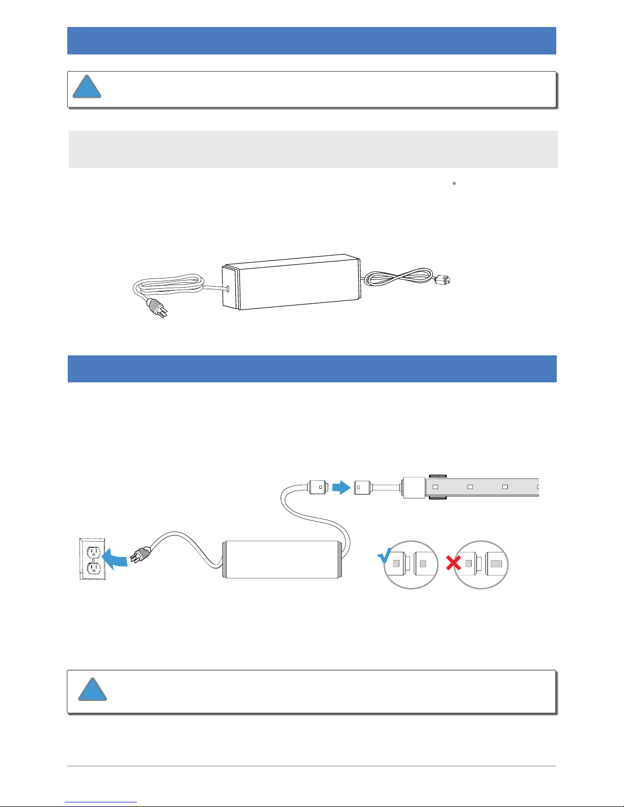
Matching the icons, connect the PS-Link Connector to the power supply. Plug the power supply
into the AC outlet.
Connect the power supply to the PS-Link Connector BEFORE
!
cabled.optiled.com
37
The power supplies for use in the United States are designed to be easily mounted
and removed to comply with UL standards.
shipped
with the power supply to install. The Velcro is suitable for indoor or outdoor installations, and
allows the power supply to easily be removed easily when necessary.
Do not plug into outlet until power supply is secured. Place power supply
!
Page 38

Issue Go Through the Solutions
None of the LED
strip is lit
Make sure power supply is plugged in and the AC power outlet is •
receiving power.
Check connection from PS-Link Connector to the power supply.•
Check the connection on the PS-Link Connector to the CabLED strip. •
Pull the strip. If it comes out of the connector, you will need a new
connector.
Only part of the
LED strip is lit
Check all connectors attached to the part of the strip that is not lit. Pull •
the CabLED strip. If it comes out of the connector, you will need a new
connector.
LED strip is
ashing On and
OFF
Check the specications for the power supply to ensure it supports the •
length of CabLED you are using. Select the appropriate strength or
install an additional power supply to support your installation.
LED strip not cut
exactly on cut
line
Depending on how you cut the strip, you may still be able to save that •
section. The cutting tolerance is about +/-3 mm (+/- 1/8 inch) on either
side of the cut line. Cutting in a straight line is crucial and the two wires
inside the strip must be pushed to the very end inside the connector to
make contact with the pins.
Go to the cut line before the cut line you incorrectly cut and make the •
section shorter. You may be able to adjust your layout by rearranging the
sections.
Contact our Customer Service Department to purchase additional •
CabLED strip. You can use an I-Connector to connect the additional
strip.
Connectors
pushed
together before
installation
If you pushed the connector top into the bottom before installation •
or if the CabLED strip was not pushed completely to the end of the
connector and did not secure the strip, you may be able to save the part.
Use a at screw driver to gently widen the sides of the top connector and
push the bottom connector apart. NOTE: This may not x the connector
and you will need to use a new connector.
Contact our Customer Service Department to purchase additional •
connectors.
Troubleshooting
38 cabled.optiled.com
Most of the problems you may encounter will be caused by improper assembly. If you have any
questions or need to purchase additional parts, please contact our Customer Service Department.
Systems Installed Without Accessories
Page 39

Email: [email protected]
Website: www.optiled.com
Patented Worldwide
 Loading...