

OPTIKA MICROSCOPES - ITALY
www.optikamicroscopes.com - info@optikamicroscopes.com
Ver. 3.0.0
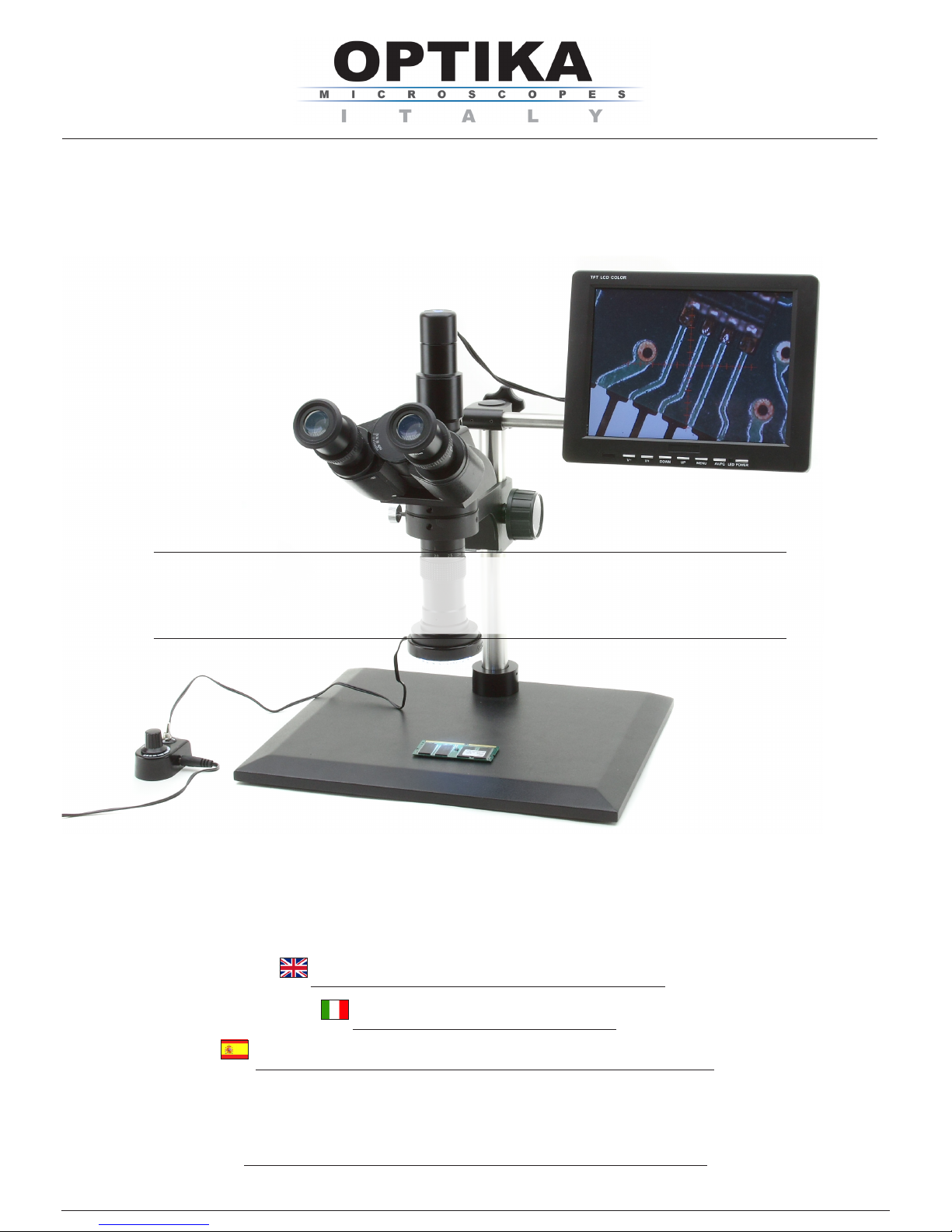
XZ-2
OPERATION MANUAL
GUIDA UTENTE
MANUAL DE INSTRUCCIONES

Page 2
INDEX
1.0 DESCRIPTION page 4
2.0 INTRODUCTION page 5
3.0 UNPACKING AND ASSEMBLY page 5
4.0 USING THE MICROSCOPE page 15
5.0 MAINTENANCE page 19
6.0 ELECTRICAL SPECIFICATIONS page 19
7.0 RECOVERY AND RECYCLING page 20
Page 3
This microscope is a scientic precision instrument designed to last for many years with a minimum of maintenance. It is built to high optical and mechanical standards and to withstand daily use.
Optika reminds you that this manual contains important information on safety and maintenance, and that it
must therefore be made accessible to the instrument users.
Optika declines any responsibility deriving from instrument uses that do not comply with this ma-nual.
Safety guidelines
This manual contains important information and warnings regarding safety about installation, use and maintenance of the microscope. Please read this manual carefully before using the equipment. To ensure safe use,
the user must read and follow all instructions in this manual. OPTIKA products are designed for safe use in
normal operating conditions. The equipment and accessories described in the manual are manufactured and
tested according to industry standards for safety instrumentation laboratory. Misuse can cause personal injury
or damage to the instrument. Keep this manual at hand close to the instrument, for an easy consultation.
Electrical safety
Before connecting the power cord to wall outlet, ensure that your mains voltage for your region corresponds
to the voltage supply of the instrument, and that the illuminator’s switch is in position OFF. The user must
observe the safety regulations in force in his region. The instrument is equipped with CE safety marking, in
any case the user has full responsibility concerning the safe use of that instrument.
Warning/Caution symbols used in this manual
The user should be aware of safety aspects when using the instrument. Warning or hazard symbols are
shown below. These symbols are used in this manual.
The instructions on this symbol to avoid possible severe personal injuries.
Warning of use; the incorrect operation on the instrument can cause damages
to the person or instrument.
Possibility of electric shock.
Attention: high temperature surfaces. Avoid direct contact.
Technical notes or usage tips.
SAFETY GUIDELINES
Page 4
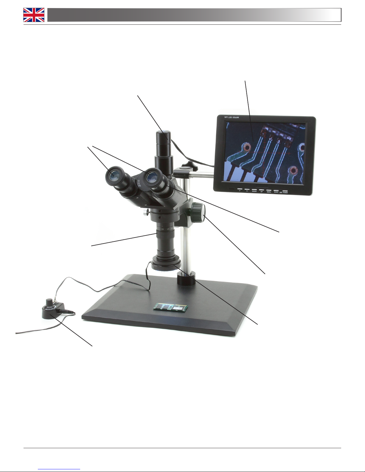
1.0 DESCRIPTION
EYEPIECES
DIGITAL CAMERA
LCD
ZOOM ADJUSTMENT
RING
LED BRIGHTNESS
CONTROL
DIOPTRIC
COMPENSATION
FOCUS / TENSION
KNOB
LED RING
ILLUMINATOR
Page 5
This microscope is a scientic precision instrument designed to last for many years with a minimum
of maintenance. It is built to high optical and mechanical standards and to withstand daily laboratory
use.
Optika reminds you that this manual contains important information on safety and maintenance, and
that it must therefore be made accessible to the instrument users.
Optika declines any responsibility deriving from instrument uses that do not comply with this ma-
nual.
3.0 UNPACKING AND ASSEMBLY
2.0 INTRODUCTION
Components of the microscope
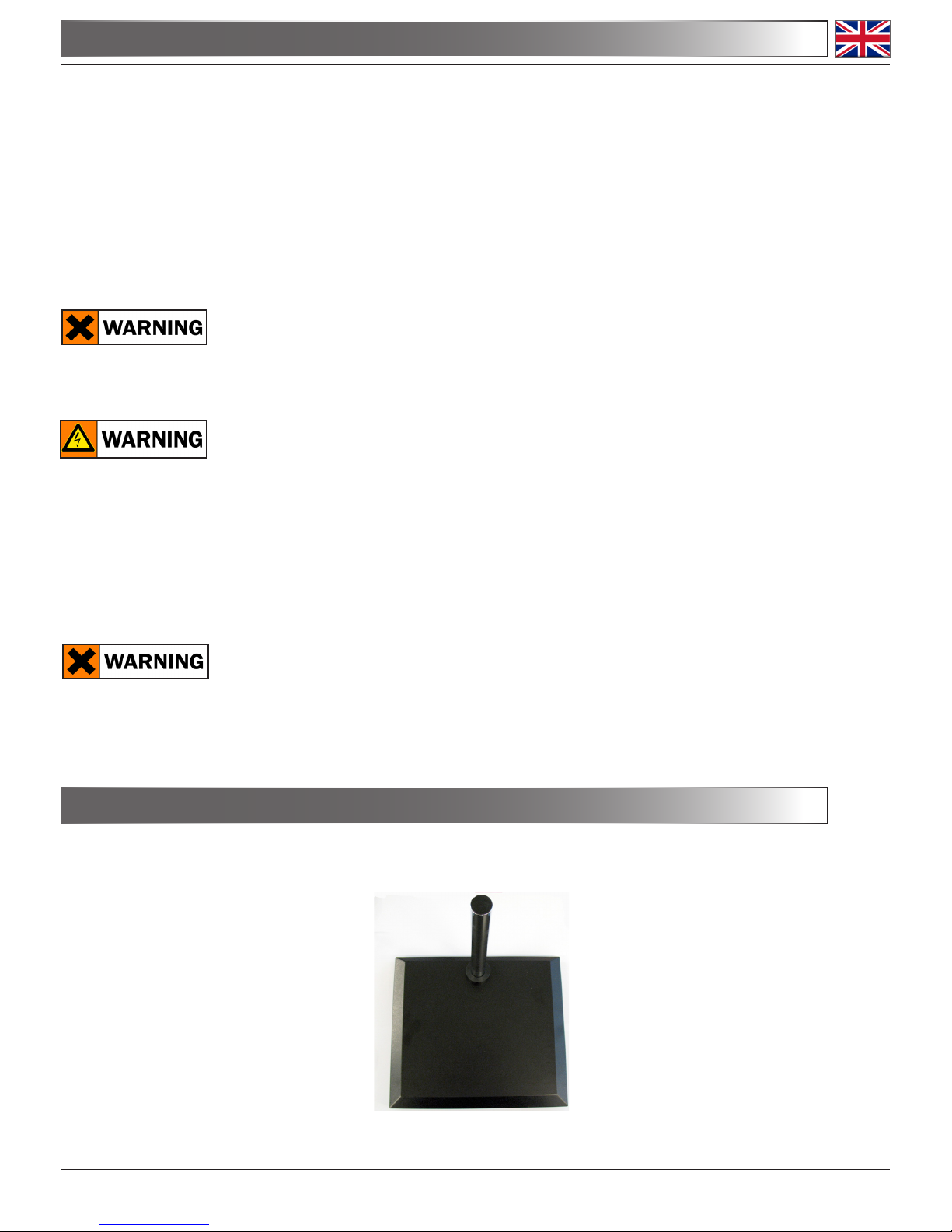
Unpack the components of the microscope from the box and put them on a stable surface. In the
packaging you nd:
1 - PILLAR BASE
Connect the mains plug into the socket at the base
Make sure, before you turn the illumination on, that the voltage selector is set to the mains voltage for your
region.
The power cord should be used only on network sockets equipped with adequate grounding.
Contact a technician to check the state of your electrical system. If there is no need to install additional acces-
sories, the instrument is now ready for use. Once positioned and installed with the necessary components,
the microscope is ready to be used. Your microscope is a laboratory instrument designed to last. Handle it
always carefully and avoid abrupt vibrations or shocks. Always disconnect the power cable from the micro-
scope when not in use for long time, while you clean it or when you perform any maintenance.
AVOID DISASSEMBLING THE INSTRUMENT
Do not disassemble the instrument. This entails the cancellation of the warranty and may cause
malfunction.

Page 6
2 - HEAD HOLDER WITH FOCUSING MECHANISM
3 - SUPPORT ROD FOR LCD
3.0 UNPACKING AND ASSEMBLY
Page 7
3.0 UNPACKING AND ASSEMBLY
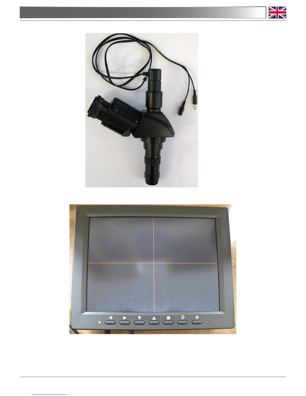
4 - OPTICAL HEAD WITH BUILT-IN DIGITAL CAMERA
5 - 8’’ TFT LCD SCREEN
Page 8
3.0 UNPACKING AND ASSEMBLY
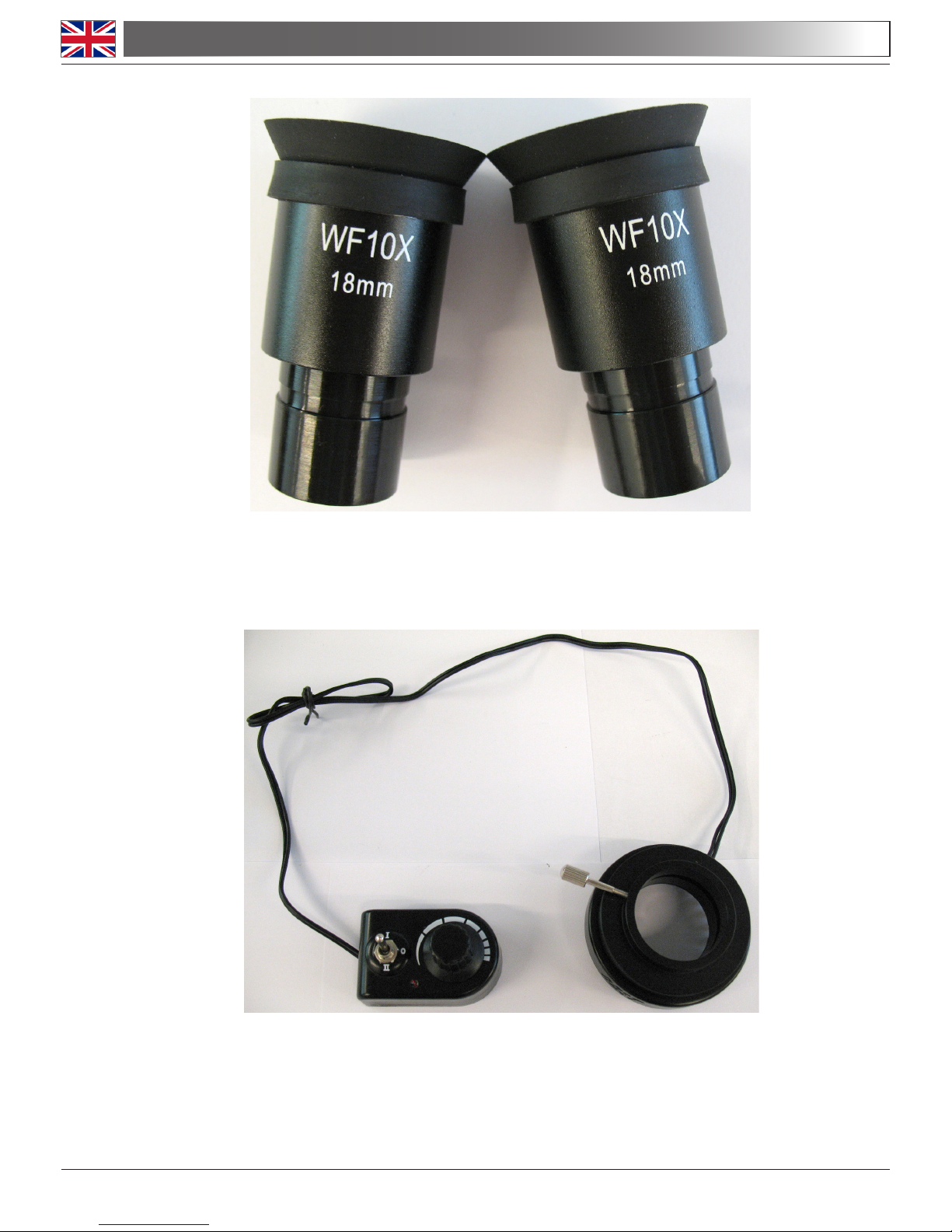
6 - EYEPIECES WF10X/18MM
7 - LED RING ILLUMINATOR WITH BRIGHTNESS CONTROL
Page 9
3.0 UNPACKING AND ASSEMBLY
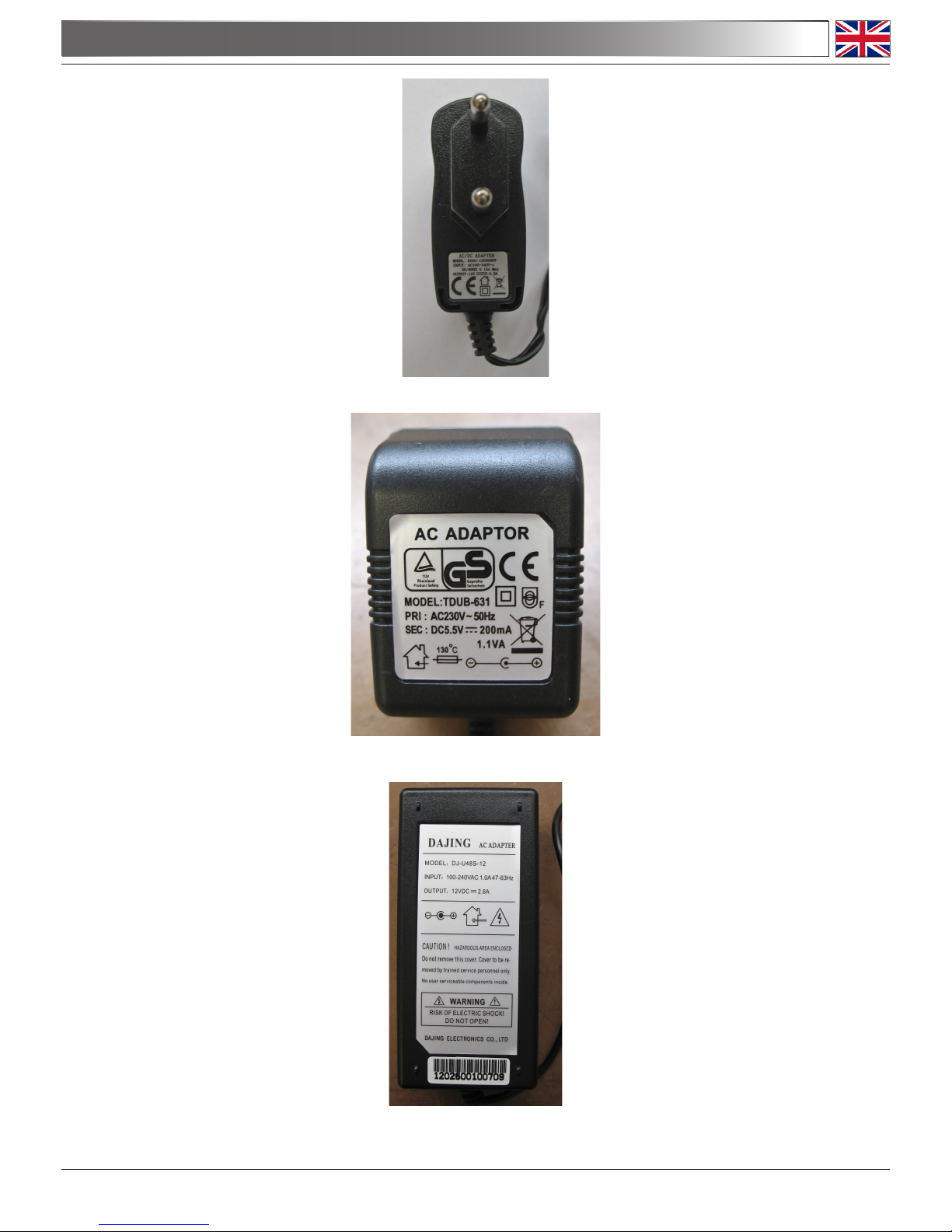
9 - DIGITAL CAMERA POWER SUPPLY (OUT: 5,5VDC 200mA)
10 - LCD SCREEN POWER SUPPLY (OUT: 12VDC 2,6A)
8 - LED RING POWER SUPPLY (OUT: 12VDC 0.5A)
Page 10
3.0 UNPACKING AND ASSEMBLY
Assembling the microscope
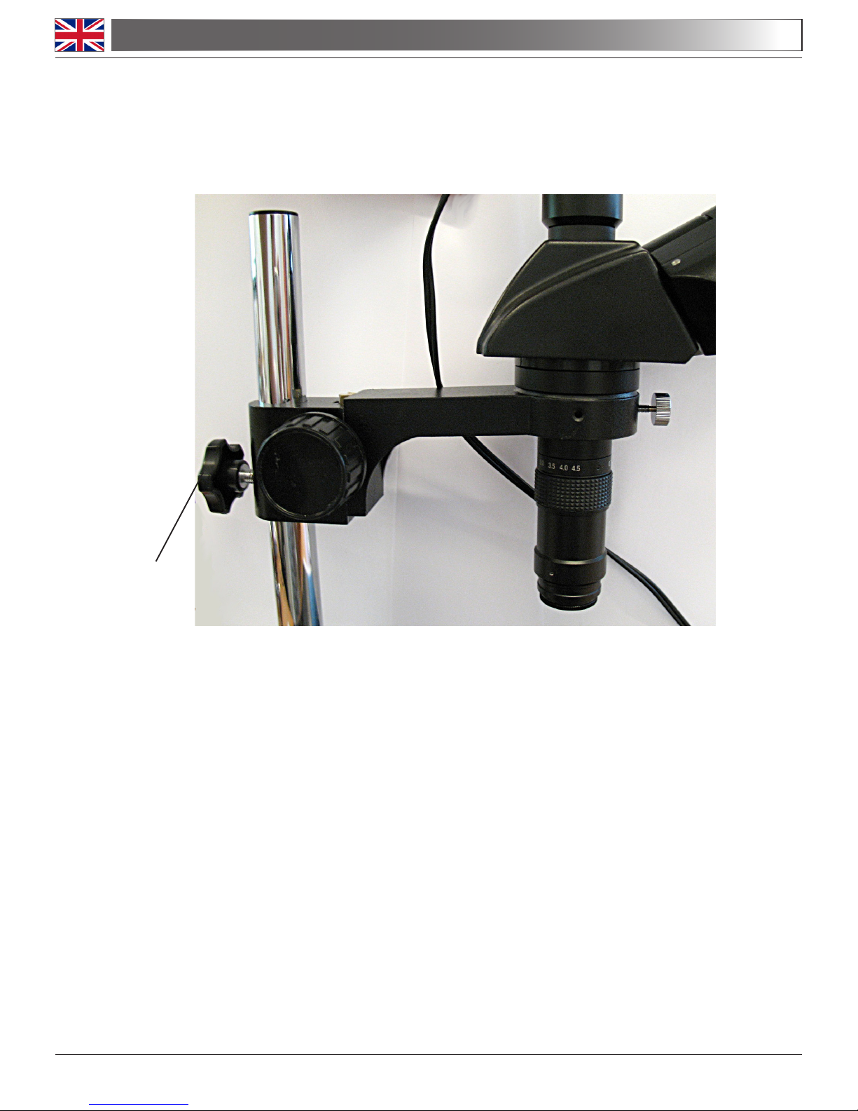
1. Put the optical head in the head holder and then slide it on the pillar. Tighten the screw on
the back at about half height of the pillar (you can move it later when you focus your sample).
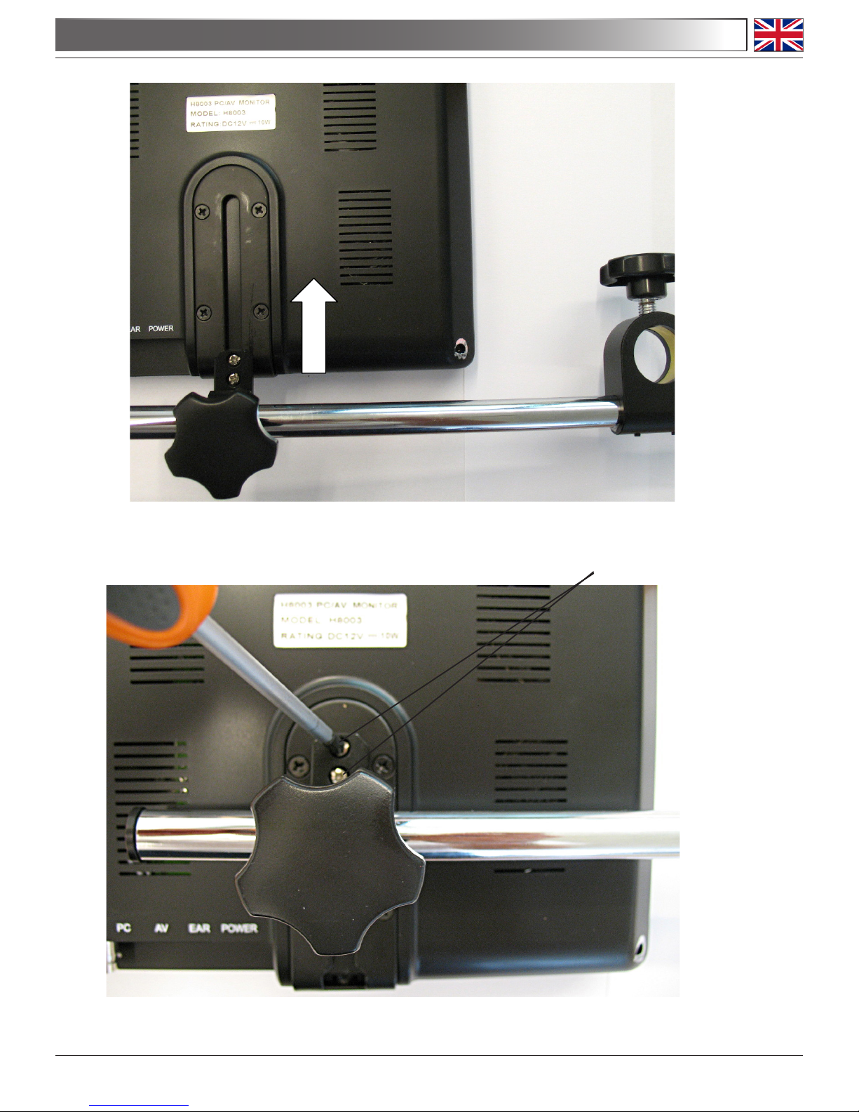
2. Put the LCD screen on a table with its rear up-facing, then insert the slider of the support
rod all the way up and tighten the two screws.
TIGHTEN THIS SCREW
Page 11
3.0 UNPACKING AND ASSEMBLY
SCREWS
Page 12
3.0 UNPACKING AND ASSEMBLY
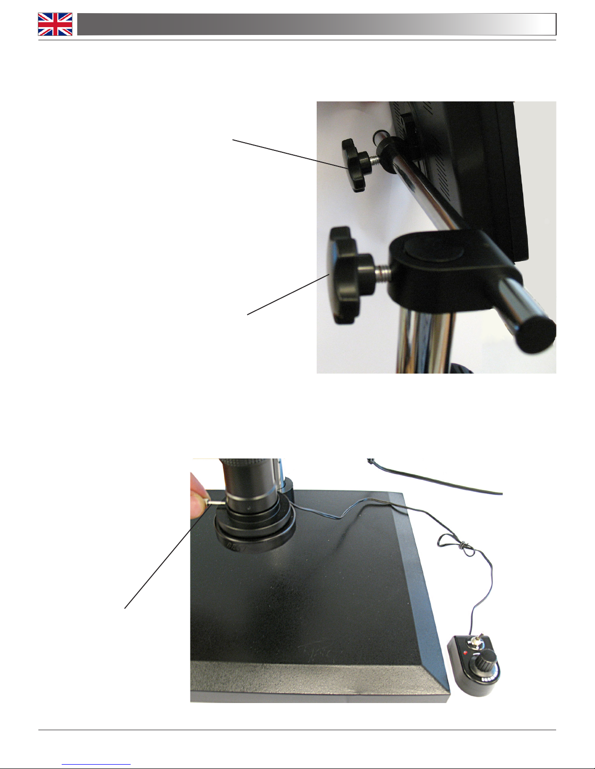
2. Put the support rod with the screen on the pillar base, locking the screw.
4. Put the LED ring illuminator at the bottom of the optical head.
USE THIS SCREW TO ADJUST
LCD INCLINATION
LOCK THIS SCREW
LOCK THIS SCREW
Page 13
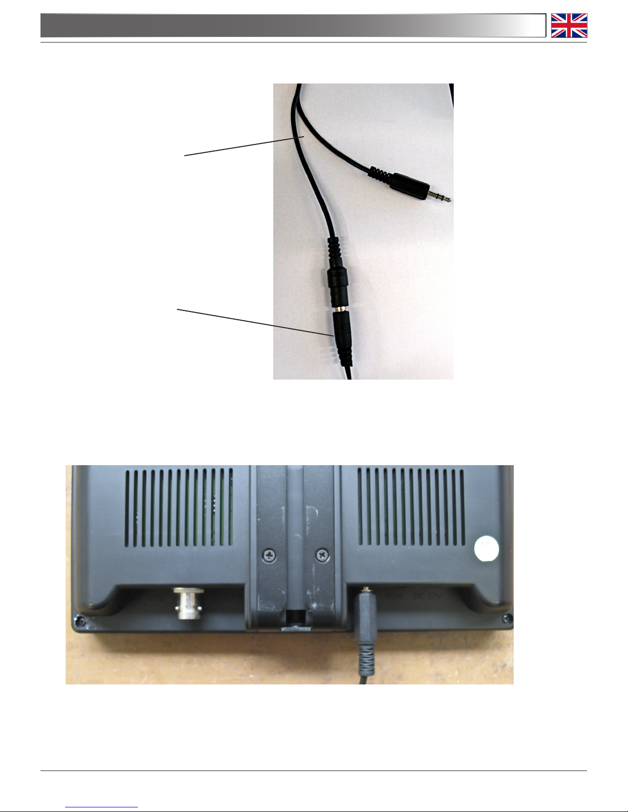
5. Take the cable connected to the digital camera, and plug it to the power supply (5,5V).
6. Plug the other jack of the digital camera cable into the AV input on the rear of the LCD screen.
DIGITAL CAMERA CABLE
JACK FROM 5,5V POWER SUPPLY
3.0 UNPACKING AND ASSEMBLY
Page 14
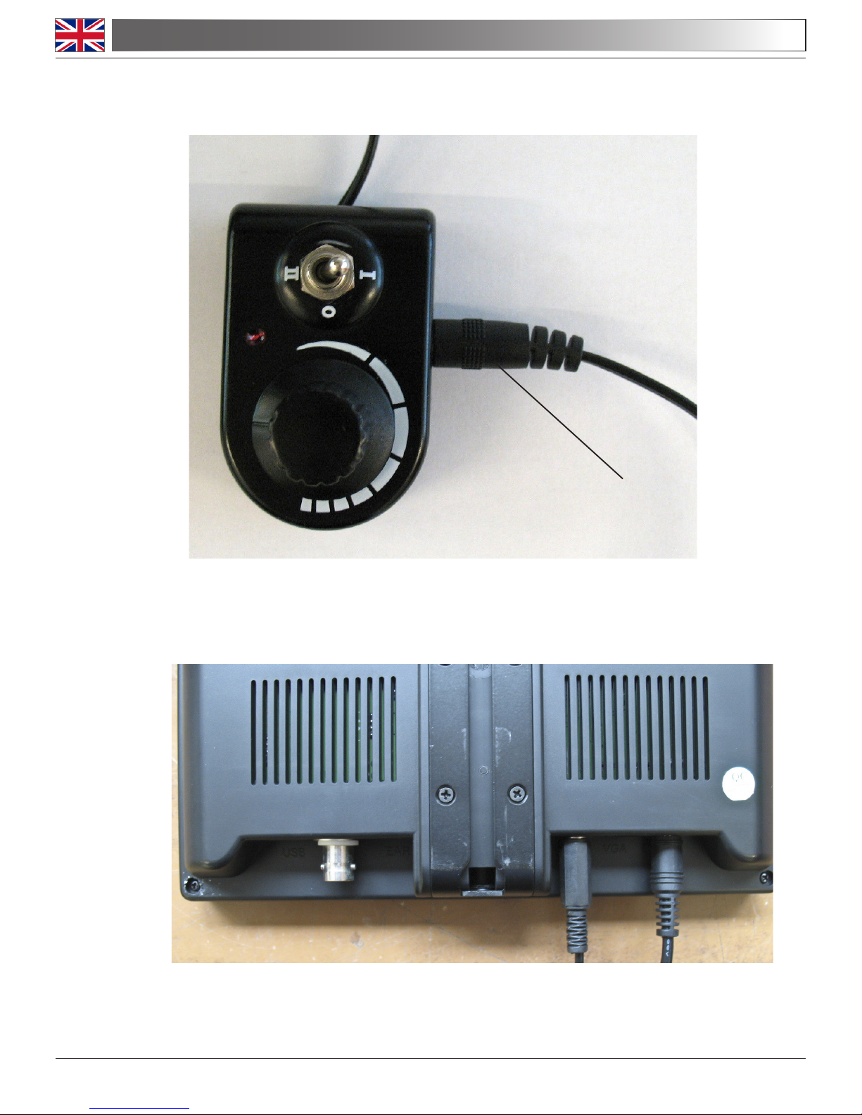
7. Plug the jack from LED ring power supply (12Vdc 0,5A) into the brightness control.
8. Plug the jack from the LCD screen power supply (12Vdc 2,6A) into the DC12V input on
the rear of the LCD screen.
Now the XZ-2 is ready to be used.
JACK FROM 12V-0.5A POWER SUPPLY
3.0 UNPACKING AND ASSEMBLY
Page 15
4.1 Switch on the power supplies and press the POWER button on the LCD screen.
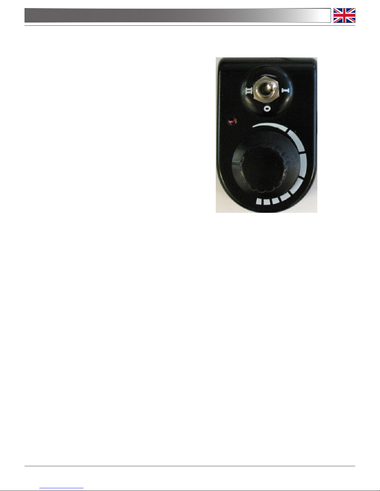
4.2 Use the brightness control to adjust the LED light:
- position 0: LED OFF
- position I: LED ON with adjustable brightness
- position II: LED ON at maximum brightness
4.3 Put your sample on the base under the objective and rotate the focusing knob to bring the
object into focus on the LCD screen.
4.4 Rotate the zoom adjustment ring at the desired magnication (zoom range: 0,7x – 4,5x). The
ring has click-stop positions at specic zoom values for precise magnications.
4.5 Focus tension adjustment: The tension of the focusing knob can be adjusted by rotating
the right focusing knob keeping still the left focusing knob.
4.6 Interpupillary distance of the optical head: move the two eyepiece tubes until only one
circular eld can be seen through the two eyepieces. If two circles appear, the interpupil-
lary distance is too big, and if 2 overlapped circles appear, the interpupillary distance is too
small.
4.7 Dioptric compensation of the optical head: this compensation makes it possible for peo-
ple with glasses to adjust the microscope to their eyes and use the microscope without glas-
ses. Turn the zoom down to the lowest magnication. Adjust the diopter compensation ring
of the right eyepiece tube until the image of the right eyepiece is clear and sharp. Repeat
the procedure for the left eyepiece. Then, check the focus of the image for the whole zoom
range. It should now be perfectly parfocal (focus is always maintained during the change of
magnication).
4.0 USING THE MICROSCOPE
Page 16
4.8 Orientation of the digital camera: in order to have the image on the LCD aligned with the
object under observation, you can rotate the digital camera on the top of the optical head.
Note that the image in the eyepieces is reversed compared to the LCD image.
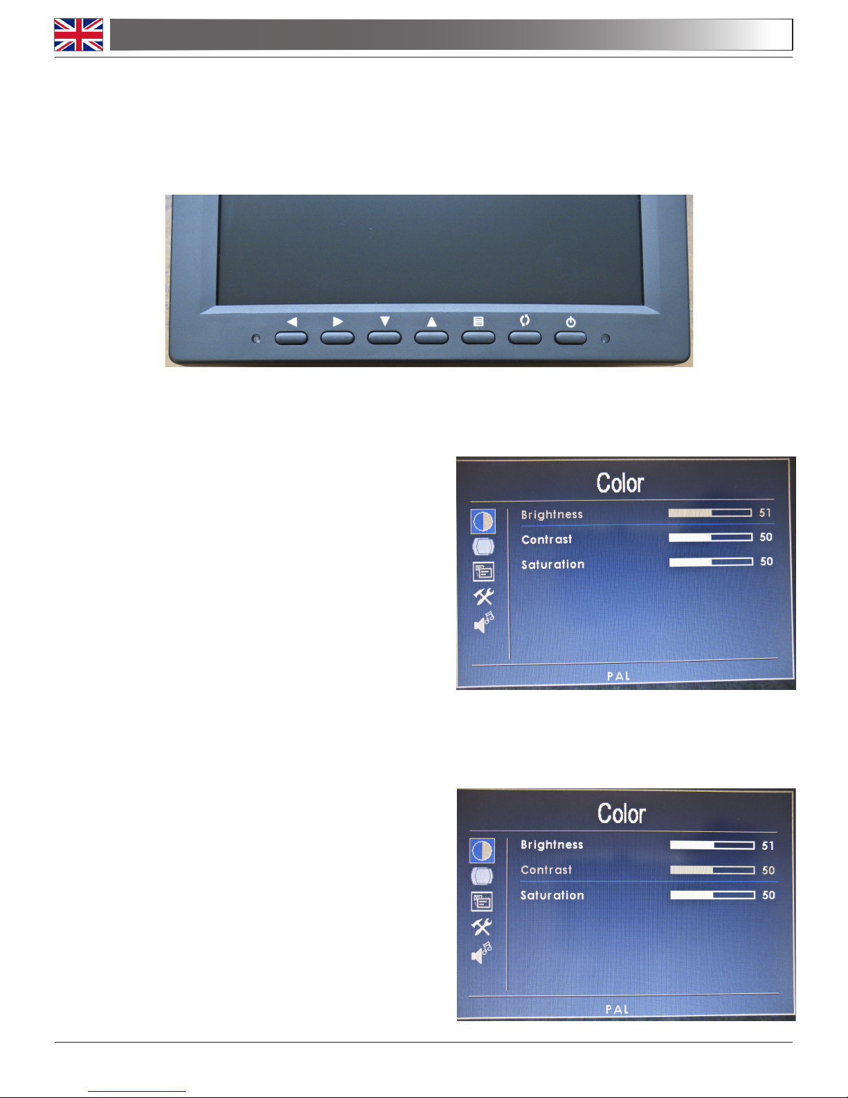
4.9 Setting the LCD screen. On the front panel of LCD you see the buttons for LCD manage-
ment:
- POWER (button at right): press this button to switch ON / OFF the screen.
- Brightness adjustment:
Press buttons:
MENU ->
►
-> ► or
◄
To exit press:
MENU
- Contrast adjustment:
Press buttons:
MENU ->
►
-> ▼ -> ► or
◄
To exit press:
MENU
4.0 USING THE MICROSCOPE
Page 17
4.0 USING THE MICROSCOPE
- Saturation adjustment:
Press buttons:
MENU ->
►
-> ▼ -> ▼ -> ► or
◄
To exit press:
MENU
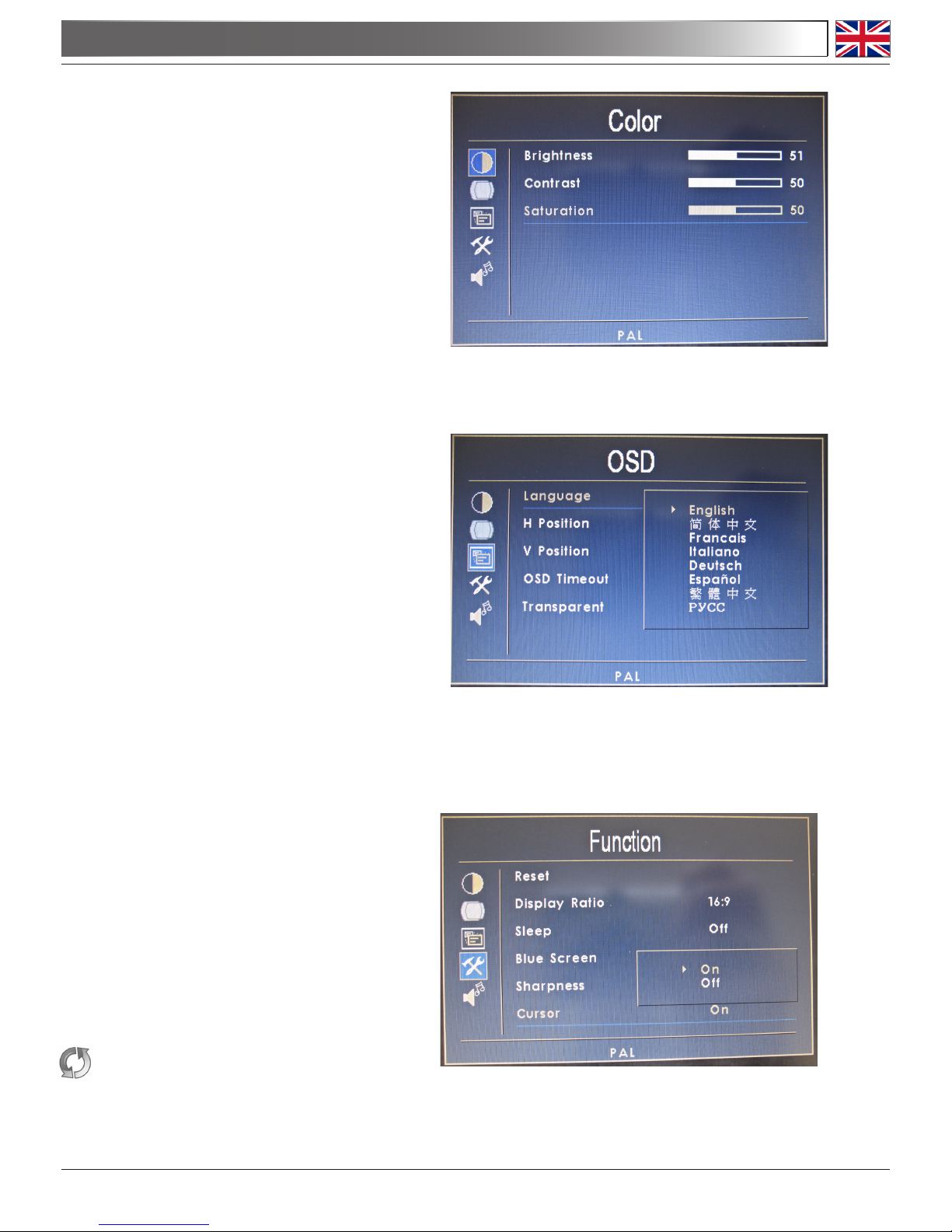
- Language selection:
Press buttons:
MENU -> ▼ -> ► -> ► -> ▲ or ▼
To save press:
►
To exit press:
MENU
- Cross display:
Press buttons:
MENU -> ▼ -> ▼ -> ► -> ▲ -> ►
-> ▲ or ▼
To save press:
►
To exit press: MENU
- Analog camera input settings:
Press button:
to select “AV” for the XZ-2 camera.
Page 18
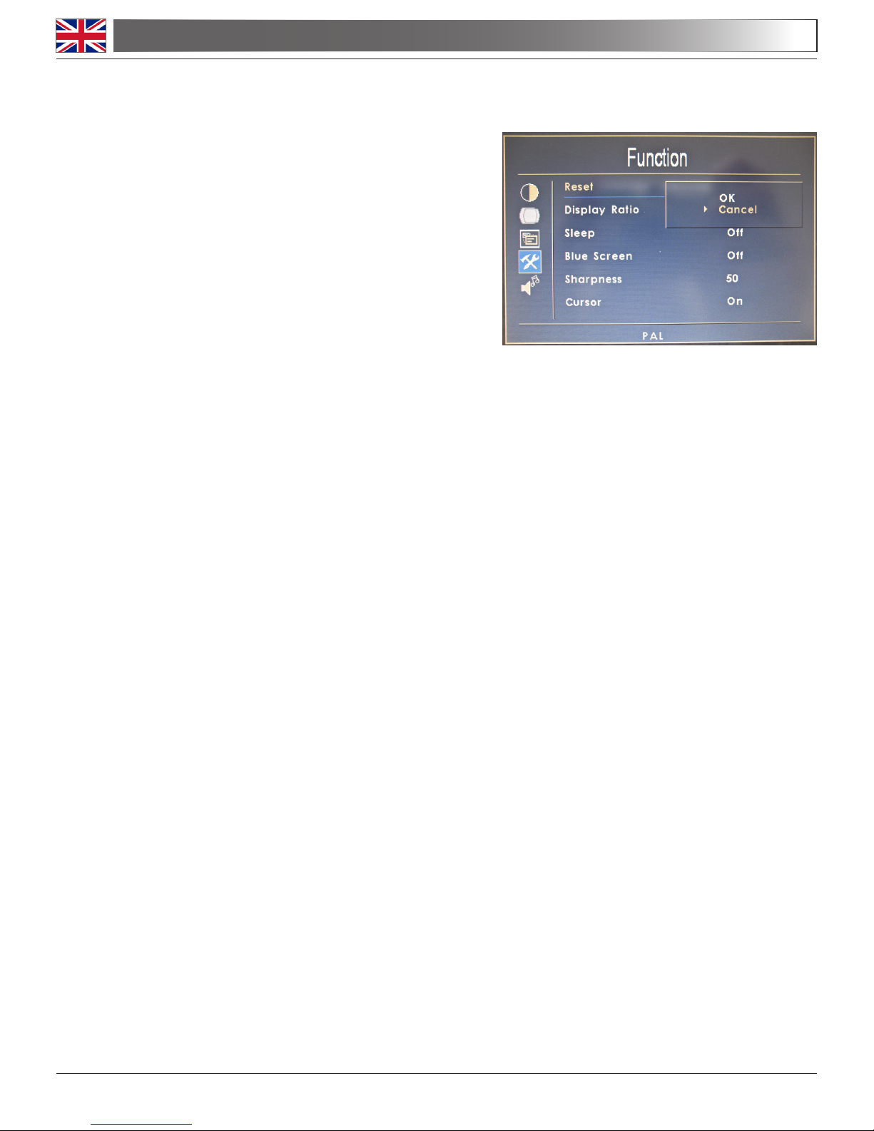
- Reset the image settings (all values set to 50):
Press buttons:
MENU ->
▲
-> ▲ -> ► -> ► -> ▲ or ▼
To save press:
►
To exit press:
MENU
4.10 Analog input. Connect an AV coaxial cable to TV connector on the rear, in order to see an
external source.
4.0 USING THE MICROSCOPE

Page 19
5.0 MAINTENANCE
5.1 Always think about
- The following environment is required: Indoor temperature: 0-40°C, Maximum relative humidi-
ty: 85 % (non condensing).
- Keep the microscope away from dust and shocks while in use.
- Turn off the light immediately after use.
- Use a soft lens tissue to clean the optics after use.
- Only if needed, use a cloth moistened with water and a mild detergent, rinsing with water and
drying immediately with a lint-free cloth.
- After use, cover the microscope with the included dust-cover, and keep it in a dry and clean
place.
5.2 Do not!
- Wipe the surface of any optical items with your hands. Fingerprints can damage the optics.
- Use solvents, neither on the microscope, nor on the optics.
- Disassemble objective or eyepieces to attempt to clean them.
- Mishandle or impose unnecessary force on the microscope.
- Clean the unit with volatile solvents or abrasive cleaners.
- Attempt to service the microscope yourself.
5.3 If you need to send the microscope to OPTIKA for maintenance, please use the original packa-
ging.
Power Supply:
INPUT: 100-230 Vac, 50/60 Hz
OUTPUTS: LED ring: 12Vdc 0.5A
Digital camera: 5,5Vdc 200mA
LCD screen: 12Vdc 2,6A
6.0 ELECTRICAL SPECIFICATIONS

Page 20
7.0 RECYCLING AND RECOVERY
Art.13 Dlsg 25 july 2005 N°151. “According to directives 2002/95/EC, 2002/96/EC and 2003/108/EC
relating to the reduction in the use of hazardous substances in electrical and electronic equipment
and waste disposal.”
The basket symbol on equipment or on its box indicates that the product at the end of its useful life
should be collected separately from other waste.
The separate collection of this equipment at the end of its lifetime is organized and managed by
the producer. The user will have to contact the manufacturer and follow the rules that he adopted
for end-of-life equipment collection. The collection of the equipment for recycling, treatment and en-
vironmentally compatible disposal, helps to prevent possible adverse effects on the environment
and health and promotes reuse and/or recycling of materials of the equipment. Improper disposal
of the product involves the application of administrative penalties as provided by the laws in force.

Pagina 21
INDICE
1.0 DESCRIZIONE page 23
2.0 INTRODUZIONE page 24
3.0 DISIMBALLAGGIO E INSTALLAZIONE page 24
4.0 UTILIZZO DEL MICROSCOPIO page 34
5.0 MANUTENZIONE page 38
6.0 SPECIFICHE ELETTRICHE page 38
7.0 MISURE ECOLOGICHE page 39

Pagina 22
Il presente microscopio è uno strumento scientico di precisione studiato per durare molti anni con una manutenzione minima, essendo costruito secondo i migliori standard ottici e meccanici e progettato per un utilizzo
quotidiano.
Optika ricorda che il presente manuale contiene informazioni importanti per un uso sicuro e una corretta manutenzione dello strumento. Esso deve quindi essere accessibile a chiunque lo utilizzi.
Optika declina ogni responsabilità derivante da un uso improprio dei suoi strumenti non indicato dalla presente guida.
Avvertenze di sicurezza
Questo manuale contiene importanti informazioni e avvertenze riguardanti la sicurezza riguardo l’installazione, l’utilizzo e la manutenzione del microscopio. Si raccomanda di leggere attentamente il manuale prima
di qualsiasi utilizzo dello strumento. Per assicurare un utilizzo sicuro l’utente deve leggere e seguire tutte le
istruzioni poste nel presente manuale.
I prodotti OPTIKA sono studiati per un utilizzo sicuro in condizioni operative normali. Lo strumento e gli accessori descritti nel manuale sono realizzati e testati secondo standard industriali di sicurezza per strumentazione da laboratorio.
L’utilizzo non corretto può causare lesioni alla persona o danni allo strumento.
Mantenere questo manuale a portata di mano vicino allo strumento, per una facile consultazione.
Precauzioni di sicurezza elettrica
Prima di collegare il cavo di alimentazione alla presa di rete, assicurarsi che la tensione di rete della vostra
regione corrisponda alla tensione di alimentazione dello strumento, e che l’interruttore dell’illuminatore sia in
posizione spenta.
L’utente deve osservare la regolamentazione riguardante la sicurezza in vigore nel proprio Stato. Lo strumento è dotato di marcatura di sicurezza CE, in ogni caso l’utente ha piena responsabilità riguardo all’utilizzo
sicuro dello strumento stesso.
Simboli di avvertenza/pericolo usati nel manuale
L’utente deve essere a conoscenza degli aspetti legati alla sicurezza nel momento in cui utilizza lo strumento.
I simboli di avvertenza o pericolo sono indicati sotto. Tali simboli sono utilizzati in questo manuale di istruzio-
ni.
Seguire le istruzioni contrassegnate da questo simbolo per evitare possibili gra-
vi danni alle persone.
Avvertimento di utilizzo; la non corretta operazione sullo strumento può causare
danni alla persona o allo strumento.
Possibilità di shock elettrico.
Attenzione: superci ad elevata temperatura. Evitare il contatto diretto.
Note tecniche o consigli di utilizzo.
INDICAZIONI PER LA SICUREZZA

Pagina 23
1.0 DESCRIZIONE
OCULARI
TELECAMERA DIGITALE
LCD
GHIERA
REGOLAZIONE
ZOOM
CONTROLLO LUMINOSITÀ
LED
COMPENSAZIONE
DIOTTRICA
MANOPOLA
FUOCO / REGOLAZIONE
TENSIONE
ANELLO
ILLUMINATORE
LED

Pagina 24
Questo microscopio è uno strumento scientico di precisione duraturo negli anni e con una manu-
tenzione minima. Viene costruito secondo i migliori standard ottici e meccanici ed è resistente ad un
utilizzo quotidiano in aula o in laboratorio.
Optika ricorda che questo manuale contiene informazioni importanti per un uso sicuro ed una manu-
tenzione corretta del microscopio. Esso dovrebbe quindi essere visionato da chiunque lo utilizzi.
Optika declina ogni responsabilità circa i suoi strumenti in caso di uso improprio e non contemplato
dal presente manuale.
3.0 DISIMBALLAGGIO E INSTALLAZIONE
2.0 INTRODUZIONE
Componenti del microscopio
Estrarre i componenti dall’imballo e disporli su una supercie piana. Nell’ imballo trovate:
1 – BASE CON COLONNA
Connettere il cavo di alimentazione nella presa posta nella base dello stativo.
Assicurarsi, prima dell’accensione, che il selettore del voltaggio sia impostato sulla tensione di rete della
vostra regione.
Il cavo di alimentazione deve essere utilizzato solo su prese di rete dotate di adeguata messa a terra.
Contattare un vostro tecnico per assicurarsi sullo stato dell’impianto elettrico. Se non vi è necessità di instal-
lare altri accessori, lo strumento è ora pronto per l’utilizzo. Una volta posizionato e installato con i necessari
componenti, il microscopio è pronto per l’utilizzo. Il vostro microscopio è uno strumento da laboratorio pro-
gettato per durare a lungo. Maneggiatelo sempre con cura ed abitate brusche vibrazioni o colpi.Scollegare
sempre il cavo di alimentazione dal microscopio quando non viene utilizzato per lunghi tempi, mentre lo si
pulisce o quando si esegue una qualsiasi manutenzione.
EVITARE DI SMONTARE LO STRUMENTO
Non disassemblare lo strumento. Questo comporta l’annullamento della garanzia e potrebbe causare mal-
funzionamenti.

Pagina 25
2 – SUPPORTO TESTATA CON MECCANISMO DI FUOCO
3 – ASTA DI SUPPORTO PER LCD
3.0 DISIMBALLAGGIO E INSTALLAZIONE

Pagina 26
3.0 DISIMBALLAGGIO E INSTALLAZIONE
4 – TESTATA OTTICA CON TELECAMERA INTEGRATA
5 – SCHERMO LCD 8’’ TFT

Pagina 27
3.0 DISIMBALLAGGIO E INSTALLAZIONE
6 - OCULARI WF10X/18MM
7 – ANELLO A LED CON CONTROLLO DELLA LUMINOSITÀ

Pagina 28
3.0 DISIMBALLAGGIO E INSTALLAZIONE
9 – ALIMENTATORE PER TELECAMERA DIGITALE (USCITA: 5,5VCC 200mA)
10 – ALIMENTATORE SCHERMO LCD(USCITA: 12VCC 2,6A)
8 – ALIMENTATORE PER ANELLO LED (USCITA: 12VCC 0.5A)

Pagina 29
3.0 DISIMBALLAGGIO E INSTALLAZIONE
Assemblare il microscopio
1. Porre la testata ottica nel supporto e quindi inlarlo sulla colonna. Stringere la vite sul retro
a circa metà altezza (potrete regolare successivamente questa altezza in fase di messa a
fuoco).
2. Posizionare il monitor LCD su un piano, con la parte posteriore rivolta verso l’alto, quindi
inserire la guida dell’asta no in fondo e stringere le due viti per ssarla.
STRINGERE
QUESTA VITE

Pagina 30
3.0 DISIMBALLAGGIO E INSTALLAZIONE
VITI

Pagina 31
3.0 DISIMBALLAGGIO E INSTALLAZIONE
3. Inlare l’asta di supporto con il monitor sulla colonna, stringendo la vite di bloccaggio.
4. Posizionare l’anello illuminatore LED in fondo alla testata ottica.
UTILIZZARE QUESTA VITE PER
REGOLARE L’INCLINAZIONE
DELL’ LCD
STRINGERE QUESTA VITE
STRINGERE
QUESTA VITE

Pagina 32
5. Prendere il cavo uscente dalla telecamera digitale, e collegarlo al jack dell’alimentatore
(5,5V).
6. Collegare l’altro jack del cavo della telecamera all’ingresso AV posto sul retro del monitor LCD.
CAVO DELLA TELECAMERA
PRESA JACK 5,5V DELL’ALIMENTATORE
3.0 DISIMBALLAGGIO E INSTALLAZIONE

Pagina 33
7. Connettere il jack dell’alimentatore dell’anello LED (12Vdc 0.5A) al regolatore di luminosità.
8. Connettere il jack dell’alimentatore del monitor LCD (12Vdc 1200mA) all’ingresso
POWER DC12V posto sul retro del monitor.
Ora il microscopio XZ-2 è pronto per essere utilizzato.
JACK DALL’ ALIMENTATORE 12V-0.5A
3.0 DISIMBALLAGGIO E INSTALLAZIONE

Pagina 34
4.1 Accendere gli alimentatori e premere il pulsante POWER del monitor LCD.
4.2 Utilizzare il regolatore di luminosità per controllare
la luce LED:
- posizione 0: LED spento
- posizione I: LED acceso con luminosità regolabile
- posizione II: LED acceso al massimo di luminosità
4.3 Posizionare il campione sulla base del microscopio, sotto l’obiettivo, e ruotare le manopole
di messa a fuoco no ad ottenere un’immagine nitida sullo schermo LCD.
4.4 Ruotare la ghiera di regolazione zoom no ad ottenere l’ingrandimento desiderato (intervallo
di zoom: 0,7x – 4,5x). La ghiera ha delle posizioni click-stop a specici valori di zoom, per
ottenere precisione nell’ingrandimento.
4.5 Regolazione della tensione di messa a fuoco: La tensione delle manopole di messa a
fuoco può essere regolata ruotando la manopola destra mentre si tiene ssa la manopola
sinistra.
4.6 Distanza interpupillare della testata: guardando negli oculari, muovere i due tubi porta-
oculari no ad ottenere la visione di un unico campo circolare. Se appaiono due cerchi sepa-
rati, la distanza interpupillare è troppo elevata; se i due cerchi sono sovrapposti, la distanza
è troppo ridotta.
4.7 Compensazione diottrica della testata : questa compensazione consente alle persone con
occhiali da vista di adattare il microscopio ai propri occhi. Portare lo zoom al valore minimo.
Regolare l’anello di compensazione diottrica dell’oculare destro no ad ottenere un’imma-
gine nitida nell’occhio destro. Ripetere la procedura per l’occhio sinistro. Quindi controllare
il fuoco dell’immagine per tutta l’estensione dello zoom. Dovrebbe risultare perfettamente
parafocale (il fuoco viene mantenuto mentre si varia l’ingrandimento).
4.0 UTILIZZO DEL MICROSCOPIO

Pagina 35
4.8 Orientazione della telecamera digitale: allo scopo di ottenere sul monitor LCD un’immagine allineata con il campione sotto osservazione, è possibile ruotare su se stessa la telecamera sulla sommità della testata ottica. Notare che l’immagine negli oculari è ribaltata rispetto a
quella nel monitor.
4.9 Impostazioni del monitor LCD: sul pannello frontale del monitor si trovano i pulsanti per
la gestione dell’ LCD:
POWER (tasto a destra): premere questo tasto per accendere/spegnere lo schermo.
- Regolazione Luminosità:
Premere il tasto:
MENU -> ► -> ► o ◄
Per uscire premere:
MENU
- Regolazione Contrasto:
Premere il tasto:
MENU -> ► -> ▼ -> ► o ◄
Per uscire premere:
MENU
4.0 UTILIZZO DEL MICROSCOPIO

Pagina 36
4.0 UTILIZZO DEL MICROSCOPIO
- Regolazione Saturazione:
Premere il tasto :
<
MENU -> ► -> ? ▼ -> ? ▼ -> ?► o ?◄
Per uscire premere:
MENU
- Selezione lingua:
Premere il tasto:
MENU -> ▼ -> ► -> ► -> ▲ o ▼
Per salvare premere:
►
Per uscire premere:
MENU
- Display incrociato:
Premere il tasto:
MENU -> ▼ -> ▼ -> ► -> ▲ -> ►
-> ▲ o ▼
Per salvare, premere: ►
Per uscire premere: MENU
- Impostazioni entrata telecamera analogica:
Premere tasto:
per selezionare “AV” per la telecamera dell’ XZ-2.

Pagina 37
- Resettaggio dell’impostazione immagine
(tutti i valori impostati su 50):
Premere il tasto:
MENU -> ▲ -> ▲ -> ► -> ► -> ▲ o ▼
Per salvare, premere:
►
Per uscire, premere:
MENU
4.10 Ingresso analogico. Connettere un cavo coassiale AV alla presa sul retro del televisore per
vedere una sorgente esterna.
4.0 UTILIZZO DEL MICROSCOPIO

Pagina 38
5.0 MANUTENZIONE
5.1 Da ricordare:
- Ambiente di lavoro con temperatura interna: 0-40°C.
Umidità relativa massima: 85% (in assenza di condensa).
- Durante l’uso proteggere il microscopio da polvere e urti.
- Spegnere la luce immediatamente dopo l’uso.
- Dopo l’uso pulire le ottiche con un apposito panno morbido.
- Solo se necessario, servirsi di un panno inumidito con acqua e un detersivo neutro, risciacquando accuratamente con acqua e asciugando immediatamente con un panno non slaccia-
to.
- Dopo l’uso coprire il microscopio con la custodia antipolvere in dotazione e tenere in un luogo
asciutto e pulito.
5.2 Da evitare:
- Non stronare la supercie di nessun componente ottico con le mani perché le impronte
digitali possono danneggiare le ottiche.
- Non utilizzare solventi né sul microscopio né sulle ottiche.
- Non smontare gli obiettivi o gli oculari per cercare di pulirli.
- Maneggiare con cura e non adoperare inutile forza sul microscopio.
- Non pulire lo strumento con solventi volatili o agenti pulenti abrasivi.
- Non cercare di provvedere da soli alla manutenzione.
5.3 Si prega di utilizzare l’imballaggio originale nel caso in cui fosse necessario rispedire il micro-
scopio a OPTIKA per la manutenzione.
Alimentazione:
INPUT: 100-230 Vac, 50/60 Hz
OUTPUT: Anello LED: 12Vdc 0.5A
Telecamera: 5,5Vdc 200mA
Monitor LCD: 2,6A
6.0 SPECIFICHE ELETTRICHE

Pagina 39
7.0 MISURE ECOLOGICHE
Ai sensi dell’articolo 13 del decreto legislativo 25 luglio 2005 n°151. “Attuazione delle direttive
2002/95/CE, 2002/96/CE e 2003/108/CE, relative alla riduzione dell’uso di sostanze pericolose nelle
apparecchiature elettriche ed elettroniche, nonché allo smaltimento dei riuti”.
Il simbolo del cassonetto riportato sulla apparecchiatura o sulla sua confezione indica che il prodotto alla
ne della propria vita utile deve essere raccolto separatamente degli altri riuti. La raccolta differenziata
della presente apparecchiatura giunta a ne vita è organizzata e gestita dal produttore.
L’utente che vorrà disfarsi della presente apparecchiatura dovrà quindi contattare il produttore e seguire
il sistema che questo ha adottato per consentire la raccolta separata dell’apparecchiatura giunta a ne
vita.
L’adeguata raccolta differenziata per l’avvio successivo della apparecchiatura dismessa al riciclaggio,
al trattamento e allo smaltimento ambientalmente compatibile contribuisce ad evitare possibili effetti
negativi sull’ambiente e sulla salute e favorisce il reimpiego e/o riciclo dei materiali di cui è composta
l’apparecchiatura.
Lo smaltimento abusivo del prodotto da parte del detentore comporta l’applicazione delle sanzioni am-
ministrative previste dalla normativa vigente.


Página 41
INDICE
1.0 DESCRIPCIÓN pag 43
2.0 INTRODUCCIÓN pag 44
3.0 DESEMBALAJE Y MONTAJE DEL MICROSCOPIO pag 45
4.0 UTILIZACIÓN DEL MICROSCOPIO pag 54
5.0 MANTENIMIENTO pag 58
6.0 ALIMENTACIÓN pag 58
7.0 MEDIDAS ECOLÓGICAS pag 59

Página 42
El microscopio es un instrumento cientíco de precisión diseñado para una larga duración con un mantenimiento mínimo. Está fabricado con materiales ópticos y mecánicos para resistir el uso diario. Optika le
recuerda que éste manual de instrucciones contiene información importante en cuanto a seguridad y mantenimiento y por lo tanto debe ser accesible a todos y cada una de las personas que van a trabajar con él.
Optika declina cualquier responsabilidad derivada del mal uso del equipo y que no haya sido especicado
en este manual.
Indicaciones de seguridad
Este manual contiene información y advertencias importantes en materia de seguridad sobre la instalación,
uso y mantenimiento del microscopio. Por favor, lea atentamente este manual antes de trabajar con el equipo. Para garantizar un uso seguro, el usuario debe leer y seguir todas las instrucciones de este manual. Los
equipos OPTIKA están diseñados para un uso seguro en condiciones normales de funcionamiento. El equipo
y los accesorios descritos en el manual son fabricados y probados de acuerdo con los estándares del sector
para laboratorio e instrumentación de seguridad. El mal uso puede causar lesiones personales o daños al
instrumento. Mantenga este manual cerca del equipo y accesible para su consulta fácil.
Seguridad eléctrica
Antes de conectar el microscopio a la toma de corriente, asegurarse que la tensión de entrada del lugar donde se vaya a trabajar coincide con la tensión de utilización del microscopio y que el interruptor del iluminador
esté en posición off.
El usuario debe consultar las normas de seguridad de su país. El instrumento está dotado de una etiqueta
de seguridad CE. A pesar de estas pautas, el usuario debería utilizar el microscopio en función de sus necesidades con un mínimo de responsabilidad y seguridad.
Por favor, siga las siguientes instrucciones y lea éste manual en su totalidad para asegurar la operación
segura del equipo.
Símbolos de advertencia / precaución utilizados en este manual
El usuario debe tener en cuenta los aspectos de seguridad al utilizar el instrumento. Símbolos de advertencia
o peligro:
Peligro: evitar posibles lesiones personales graves.
Advertencia de uso; el funcionamiento incorrecto en el instrumento puede cau-
sar daños a la persona o instrumento
Posibilidad de descarga eléctrica.
Atención: alta temperatura en la supercie. Evitar contacto directo.
Consejos de utilización
CONSEJOS DE SEGURIDAD

Página 43
1.0 DESCRIPCIÓN
OCULARES
CÁMARA DIGITAL
LCD
ANILLO
REGULACIÓN ZOOM
REGULACIÓN INTENSIDAD
LUZ LED
COMPENSACIÓN
DIÓPTRICA
MANDO
ENFOQUE/REGULACIÓN
TENSIÓN
ANILLO
ILUMINADOR LED

Página 44
El microscopio es un instrumento cientíco de precisión diseñado para durar muchos años con un
mantenimiento mínimo. Está fabricado con materiales ópticos y mecánicos para resistir el uso dia-
rio. Optika le recuerda que éste manual de instrucciones contiene información importante en cuanto
a seguridad y mantenimiento y por lo tanto debe ser accesible a todos y cada una de las personas
que van a trabajar con el microscopio. Optika declina cualquier responsabilidad derivada del mal
uso del equipo y que no haya sido especicado en este manual.
3.0 COMPONENTES DEL MICROSCOPIO
2.0 INTRODUCCIÓN
Componentes del microscopio
Extraer los componentes del embalaje y colocarlos sobre una superfície plana. En el embalaje se
incluye:
1 – BASE CON COLUMNA VERTICAL
Conecte el cable de corriente a la base del microscopio.
Asegúrese de que, antes de poner en marcha el equipo el selector de tensión está ajustado a la tensión de
red para su país : 110V o 220V
El cable de alimentación debe ser utilizado sólo en enchufes equipados con “toma de tierra”
En caso de dudas, póngase en contacto con un técnico para comprobar el estado de su sistema eléctrico. Si
no hay necesidad de instalar accesorios adicionales, el equipo está listo para trabajar. Utilícelo siempre con
cuidado y evite vibraciones o golpes bruscos. Desconecte (desenchufar) siempre el cable de alimentación
del microscopio cuando no se utiliza durante un largo periodo de tiempo, por ejemplo en vacaciones, también
mientras lo esté limpiando o al realizar cualquier operación de mantenimiento.
EVITAR DESMONTAR EL INSTRUMENTO
En caso de avería o defecto, no desmonte Ud. el instrumento ya que podría implicar la anulación de la
garantía y podría ocasionar un mal funcionamiento. Contacte con un distribuidor Optika quien le indicará los
pasos a seguir para su reparación.

Página 45
2 – SOPORTE PARA CABEZAL CON MECANISMO DE ENFOQUE
3 – BARRA DE SOPORTE PARA LA PANTALLA LCD
3.0 DESEMBALAJE Y MONTAJE

Página 46
3.0 DESEMBALAJE Y MONTAJE
4 – CABEZAL DE OBSERVACIÓN CON CÁMARA INTEGRADA
5 – MONITOR TFT 8’’

Página 47
3.0 DESEMBALAJE Y MONTAJE
6 - OCULARI WF10X/18MM
7 – ANELLO A LED CON CONTROLLO DELLA LUMINOSITÀ

Página 48
3.0 DESEMBALAJE Y MONTAJE
9 – ALIMENTADOR PARA CÁMARA DIGITAL (OUT: 9VDC 300MA)
10 – ALIMENTADOR PARA MONITOR LCD (SALIDA: 12VDC 1200MA
8 – ALIMENTADOR PARA ANILLO LED (SALIDA: 12VDC 0.5A)

Página 49
3.0 DESEMBALAJE Y MONTAJE
Montaje del microscopio
1. Situar el cabezal de observación en el soporte e introducirlo en el brazo. Apretar el tornillo
situación en la parte posterior cuando el cabezal esté a una altura aproximadamente a la
mitad de la columna vertical (es posible regular la altura sucesivamente cuando enfoque la
muestra).
2. Situar el monitor LCD en un plano con la parte posterior dirigida hacia arriba. Introducir la
guía de la barra hasta el nal y apretar los dos tornillos para jarla.
APRETAR
ESTE TORNILLO

Página 50
3.0 DESEMBALAJE Y MONTAJE
TORNILLOS

Página 51
3.0 DESEMBALAJE Y MONTAJE
3. Introducir la barra de soporte con el monitor en el brazo, apretar el tornillo de bloqueo.
4. Colocar el anillo iluminador LED en la parte inferior del cabezal de observación.
UTILIZAR ÉSTE TORNILLO
PARA REGULAR LA INCLINACIÓN DEL
LCD
APRETAR ESTE TORNILLO
APRETAR ESTE
TORNILLO

Página 52
5. Conectar el cable de salida de la cámara digital a la clavija del alimentador (5,5V).
6. Conectar el cable de la cámara digital a la entrada AV de la parte posterior del monitor LCD.
CABLE DE LA CÁMARA DIGITAL
CONECTOR DEL TRANSFORMADOR (5,5V)
3.0 DESEMBALAJE Y MONTAJE

Página 53
7. Conectar la clavija del alimentador del anillo LED (12Vdc 0,5A) al regulador de luz.
8. Conectar la clavija del alimentador del monitor LCD (12Vdc 2,6A) a la entrada DC12V
situada en la parte posterior del monitor
Ahora el microscopio XZ-2 está listo para trabajar.
CONECTOR DEL ALIMENTADOR
12V-0.5A
3.0 DESEMBALAJE Y MONTAJE

Pagina 54
4.1 Enchufar los alimentadores a la corriente y pulsar el botón “Power” del monitor LCD.
4.2 Utilizar el regulador de luz para ajustar la intesidad
del LED:
- posición 0: LED OFF apagado
- posición I: LED ON encendido con posibilidad de
ajustar laintensidad de luz
- posición II: LED ON encendido a máxima potencia.
4.3 Colocar la muestra en la base del microscopio, debajo del objetivo, y girar los mandos de
enfoque hasta que se observe en la pantalla LCD una imágen nítida.
4.4 Girar el mando de enfoque zoom hasta obtener el aumento deseado (intervalo zoom: 0,7x
– 4,5x). El anillo tiene un sistema click-stop con distintos valores zoom para conseguir unos
aumentos precisos.
4.5 Regulación de la tensión del mando de enfoque: la tensión de los mandos de enfoque
se pueden regular girando el mando derecho mientras se mantiene jo el mando izquierdo.
4.6 Distancia interpupilar del cabezal: observando a través de los oculares, mover los dos
tubos porta-oculares hasta obtener la visión de un único campo circular. Si aparecen dos
círculos separados, la distancia interpupilar está demasiado amplia; si los dos circulos están
superpuestos, la distancia es demasiado cercana.
4.7 Compensación dióptrica: Esta compensación permite a las personas que utilizan gafas
adaptar el microscopio a su visión. Colocar el zoom en el valor mínimo. Regular el anillo de
compensación dióptrica del ocular derecho hasta obtener una imágen clara y nítida con el
ojo derecho. Repetir la operación con el ojo izquierdo y a continuación, vericar el enfoque
de la imagen a lo largo de todo el intervalo zoom. Debería resultar perfectamente parafocal
(es decir, la muestra se mantiene enfocado a lo largo de todo el recorrido zoom).
4.0 UTILIZACIÓN DEL MICROSCOPIO

Página 55
4.8 Orientación de la cámara digital: para obetener en el monitor LCD una imagen alineada
cuando se está observando la muestra, es posible girar la cámara digital en el extremo
supoerior del cabezal de observación. Tener en cuenta que la imágen que aparece a
través de los oculares se ve a la inversa que en pantalla.
4.9 Conguración del monitor LCD: En el panel frontal del monitor se sitúan los mandos
para la gestión del monitor LCD
POWER – pulsar éste botón para encender o apagar el monitor.
- Ajuste del brillo: Pulsar
los botones:
MENU -> ► -> ► o ◄
Para salir pulsar:
MENU
- Ajuste contraste:
Pulsar botones:
MENU -> ► -> ▼ -> ► o ◄
Para salir pulsar:
MENU
4.0 UTILIZACIÓN DEL MICROSCOPIO

Página 56
4.0 UTILIZACIÓN DEL MICROSCOPIO
- Ajuste Saturación:
Pulsar botones:
<
MENU -> ► -> ? ▼ -> ? ▼ -> ?► o ?◄
Para salir pulsar:
MENU
- Selección Idioma:
Pulsar botones:
MENU -> ▼ -> ► -> ► -> ▲ o ▼
Para guardar pulsar:
►
Para salir pulsar:
MENU
- Mostrar micrómetro en cruz:
Pulsar botones:
MENU -> ▼ -> ▼ -> ► -> ▲ -> ►
-> ▲ o ▼
Para guardar pulsar: ►
Para salir pulsar: MENU
- Introducir conguración:
Cámara analógica: Pulsar boton:
Para seleccionar “AV” en la cámara del XZ-2.

Página 57
- Restablecer los ajustes de imagen
(todos los valores establecidos hasta 50):
Pulsar botones:
MENU -> ▲ -> ▲ -> ► -> ► -> ▲ o ▼
Para guardar pulsar:
►
Para salir pulsar:
MENU
4.10 Salida analógica. Para ver la imagen en una TV o pantalla externa, conectar un cable de
video coaxial AV al conector TV situado en la parte posterior de la pantalla.
4.0 UTILIZACIÓN DEL MICROSCOPIO

Página 58
5.0 MANTENIMIENTO
5.1 A tener en cuenta::
- Se aconseja utilizar éste microscopio en un ambiente limpio y seco. La temperatura recomen-
dada de trabajo es de 0-40º C y la humedad relativa máxima es de 85% (sin condensación).
- Trabajar en un lugar limpio, sin partículas de polvo y evitar golpear el microscopio.
- Apagar la luz inmediatamente después de trabajar con el microscopio.
- limpiar las ópticas con u paño suave, del mismo tipo que los paños utilizados para limpiar las
gafas.
- Humedecer en agua y detergente neutro y secar delicadamente e inmediatamente con un
paño que no suelte “hilos/bras”
- Cubrir el microscopio con su funda antipolvo. Mantener en lugar limpio y seco
5.2 EVITAR:
- Frotar la supercie de los componentes ópticos con las manos.
Las huellas digitales pueden dañar las ópticas.
- Utilizar disolventes abrasivos para limpiar el microscopio o las lentes.
- Desmontar objetivos u oculares para limpiarlos.
- Usar una fuerza mayor de la necesaria al trabajar con el microscopio
- Reparar el microscopio por su cuenta.
5.3 5.3 Le recomendamos guardar la caja original del microscopio. Si fuera necesaria una repara-
ción o mantenimiento y el equipo se hubiera que enviar a Optika rogamos utilice la caja original
para un transporte más seguro.
Alimentación:
ENTRADA: 100-230 Vac, 50/60Hz
SALIDA: Anillo LED: 12 Vdc 0.5A
Cámara digital: 5,5 Vdc 200mA
Monitor LCD: 2,6A
6.0 ALIMENTACIÓN

En conformidad con el Art. 13 del D.L. de 25 julio 2005 n°151.Actuación de las Directivas 2002/95/CE,
2002/96/CE y 2003/108/CE, relativas a la reducción del uso de sustancias peligrosas en la instrumentación
eléctrica y electrónica y a la eliminación de residuos.
El símbolo del contenedor que se muestra en la instrumentación o en su embalaje indica que el producto
cuando alcanzará el nal de su vida útil se deberá recoger de forma separada del resto de residuos. La gestión de la recogida selectiva de la presente instrumentación será llevada a cabo por el fabricante.Por lo tanto,
el usuario que desee eliminar la presente instrumentación tendrá que ponerse en contacto con el fabricante y
seguir el sistema que éste ha adoptado para permitir la recogida selectiva de la instrumentación. La correcta
recogida selectiva de la instrumentación para su posterior reciclaje, tratamiento y eliminación compatible con
el ambiente contribuye a evitar posibles efectos negativos al ambiente y a la salud y favorece su reutilización
y/o reciclado de los componentes de la instrumentación.
La eliminación del producto de forma abusiva por parte del usuario implicaría la aplicación de las sanciones
administrativas previstas en la normativa vigente.
7.0 MEDIDAS ECOLÓGICAS

www.optikamicroscopes.com
info@optikamicroscopes.com
OPTIKA
Tel.: ++39 035 571392 (6 linee) Telefax: ++ 39 035
Via Rigla 30, Ponteranica (BG) -
S.R.L.
ITALY
571435
MAD Iberica Aparatos
c/. Puig i Pidemunt, nº 28 1º 2ª - (Pol. Ind. Plà d’en Boet) 08302 MATARO
(Barcelona) España Tel: +34 937.586.245 +34 937.414.529
Cientificos
New York Microscope Company Inc
100 Lauman Lane, Suite A, Hicksville, New York 11801, USA
Tel.: 877.877.7274 - Fax: 516.801.2046
www.microscopeinternational.com -
OPTIKA MICROSCOPES -
www.optikamicroscopes.com -
info@nyscopes.com
ITALY
info@optikamicroscopes.com
 Loading...