

Optika STEREO, SFX, SFX-32, SFX-33, MS-2 Instruction Manual
...
SFX/STEREO Series
INSTRUCTION MANUAL
Model
MS-2
STX
SFX-31
SFX-32
SFX-33
SFX-34
SFX-51
SFX-52
SFX-91
SFX-91D
ST-30FX
ST-50Led
v 1.3 2017

Page 2

Warning
This microscope is a scientic precision instrument designed to last for many years with a minimum of maintenance. It is built to high optical and mechanical standards and to withstand daily use. We remind you that this
manual contains important information on safety and maintenance, and that it must therefore be made accessible to the instrument users. We decline any responsibility deriving from incorrect instrument use uses that does
not comply with this manual.
Symbols and conventions
The following chart is an illustrated glossary of the symbols that are used in this manual.
CAUTION
This symbol indicates a potential risk and alerts you to proceed with caution.
ELECTRICAL SHOCK
This symbol indicates a risk of electrical shock.
Safety Information
Avoiding Electrical Shock
Before plugging in the power supply, make sure that the supplying voltage of your region matches with the
operation voltage of the equipment and that the lamp switch is in o position. Users should observe all safety
regulations of the region. The equipment has acquired the CE safety label. However, users have full responsibility to use this equipment safely. Please follow the guidelines below, and read this manual in its entirety to ensure
safe operation of the unit.
Intended use
For teaching use only. Not intended for any animal or human therapeutic or diagnostic use.
Page 3
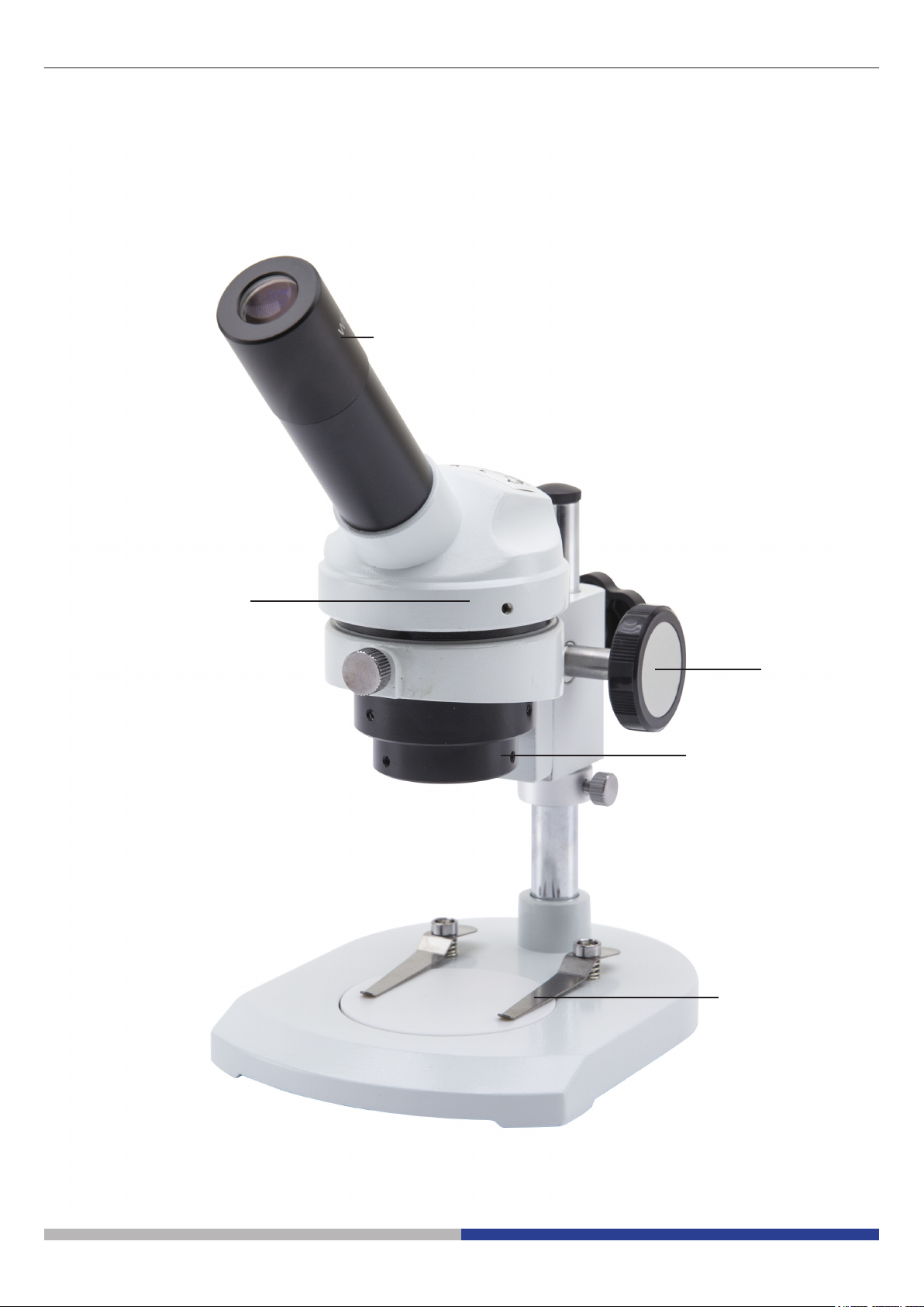
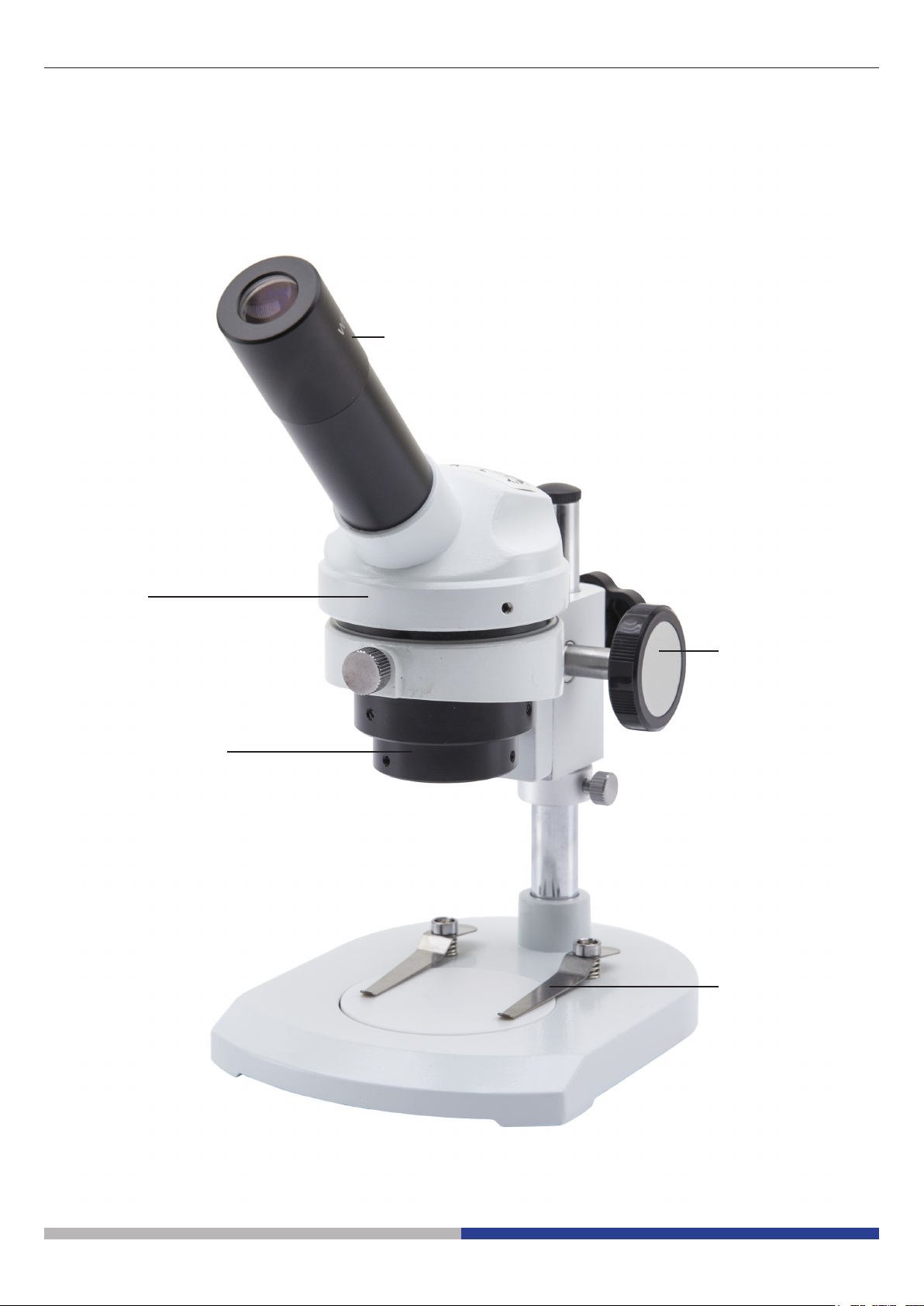
Overview MS-2
EYEPIECE
OBSERVATION
HEAD
FOCUS KNOB
OBJECTIVE
SLIDE CLAMP
Page 4

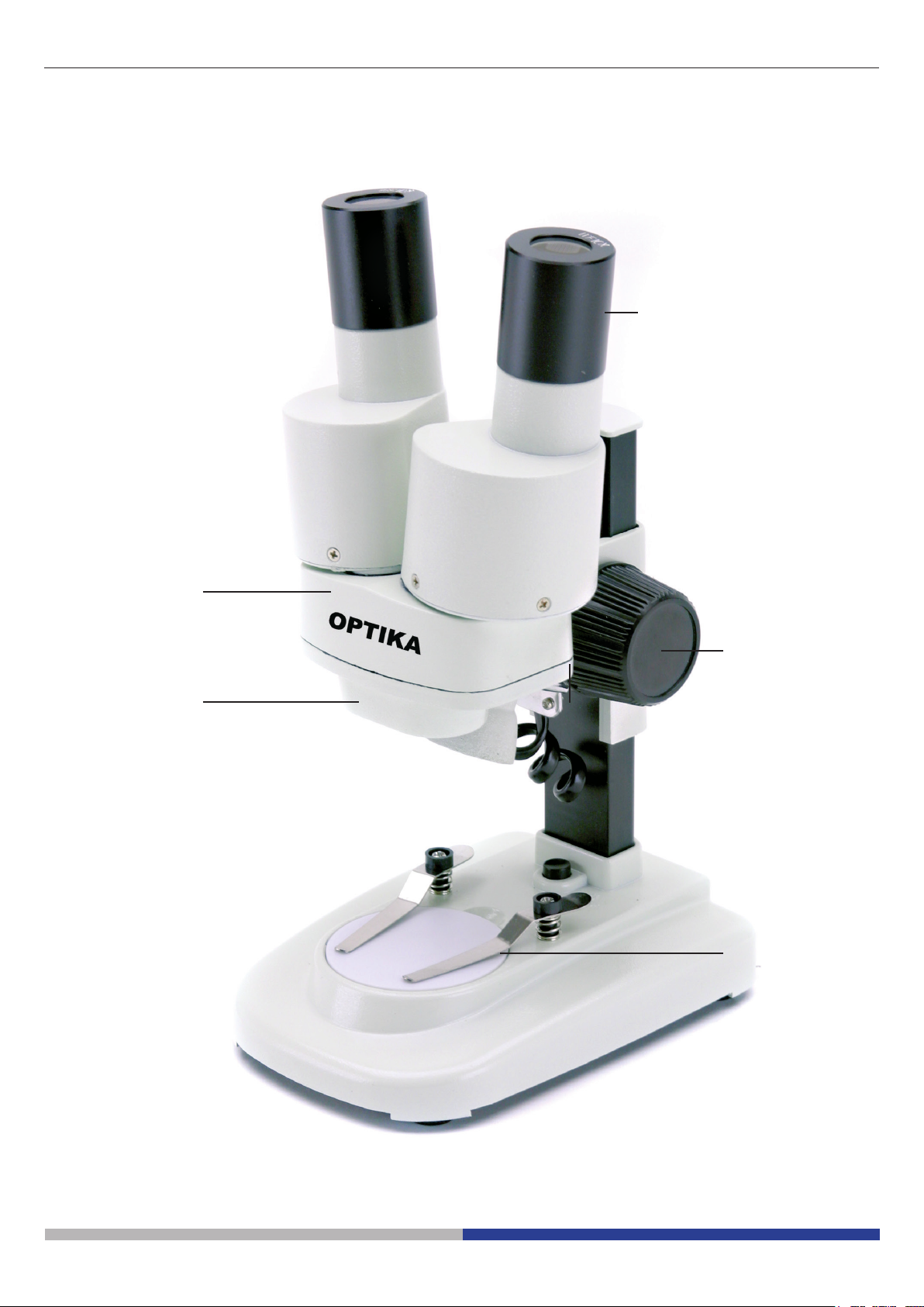
Overview STX
EYEPIECES
OBSERVATION
HEAD
OBJECTIVE
FOCUS KNOB
SLIDE CLAMP
Page 5

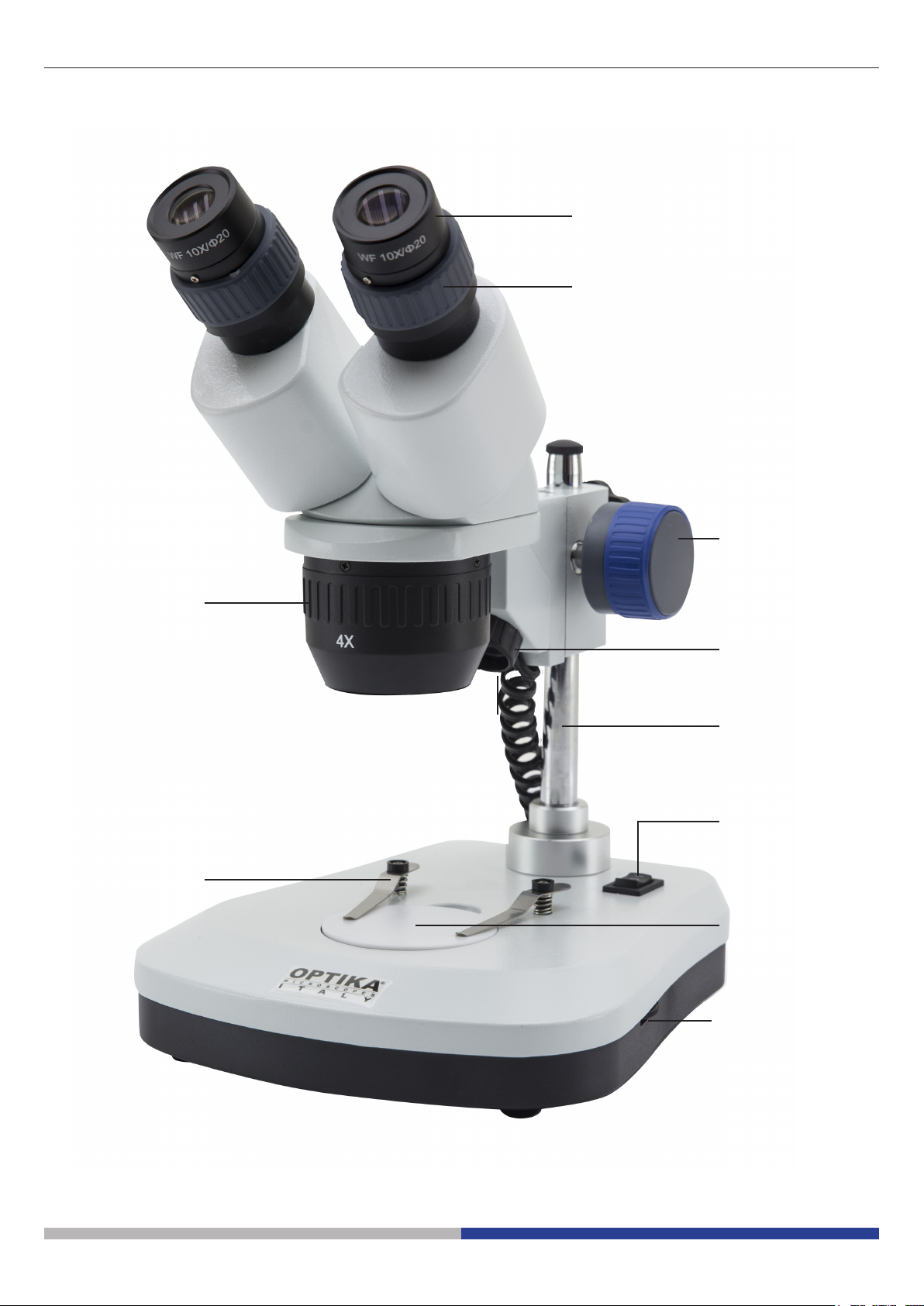
Overview SFX-31
EYEPIECES
DIOPTRIC
COMPENSATION
FOCUS KNOB
TURNABLE
OBJECTIVE
SLIDE CLAMP
INCIDENT LIGHT
STAND
ON-OFF SWITCH
TRANSMITTED
LIGHT
LIGHT
INTENSITY
ADJUSTMENT
Page 6
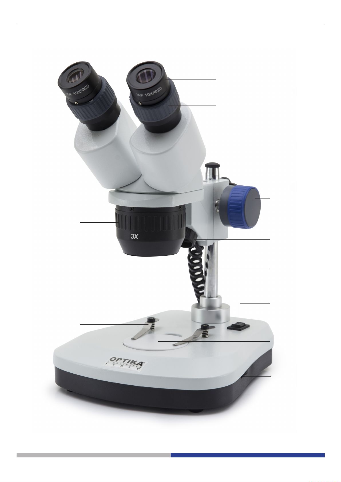
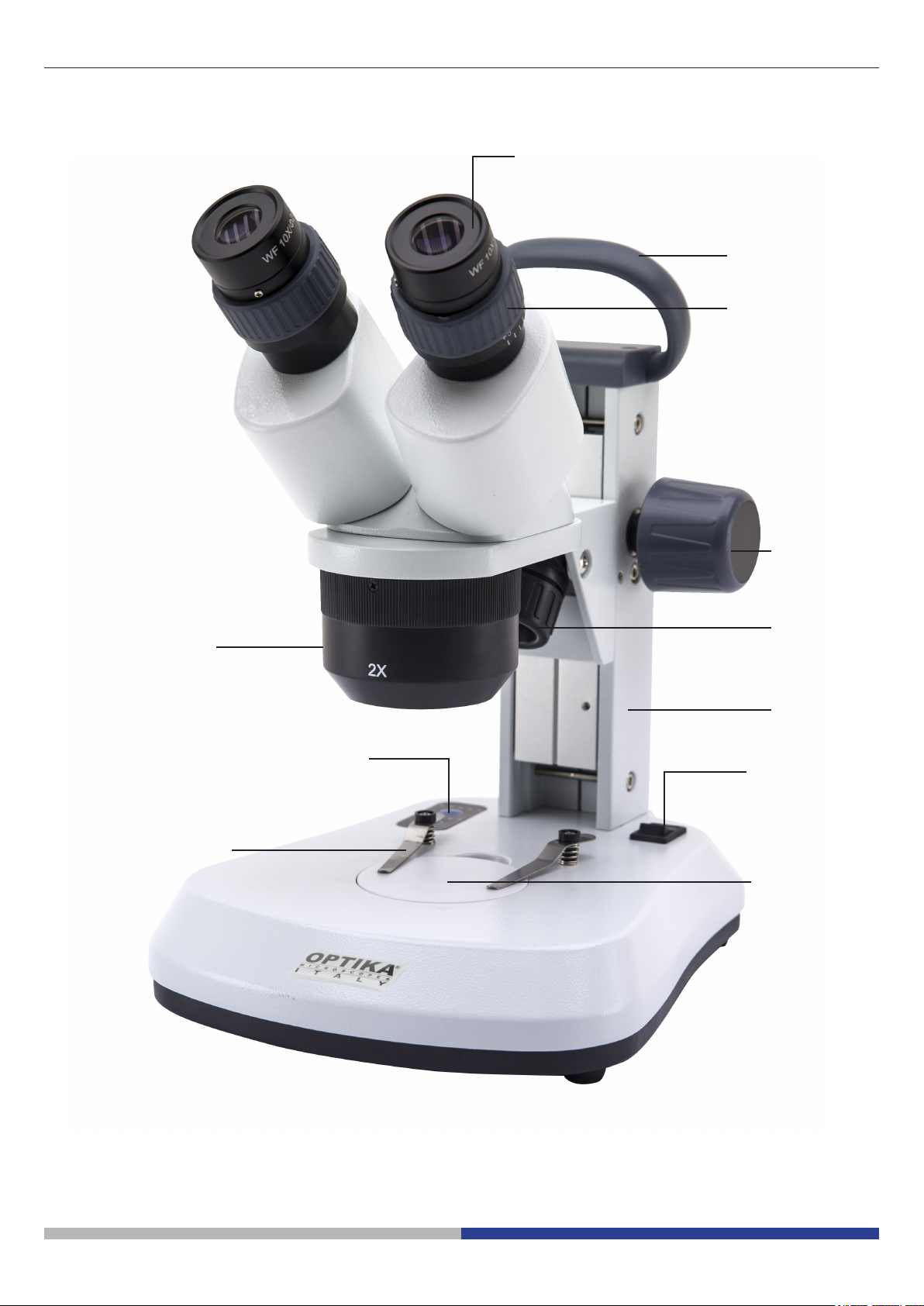
Overview SFX-32
EYEPIECES
DIOPTRIC
COMPENSATION
FOCUS KNOB
TURNABLE
OBJECTIVE
SLIDE CLAMP
INCIDENT LIGHT
STAND
ON-OFF SWITCH
TRANSMITTED
LIGHT
LIGHT
INTENSITY
ADJUSTMENT
Page 7

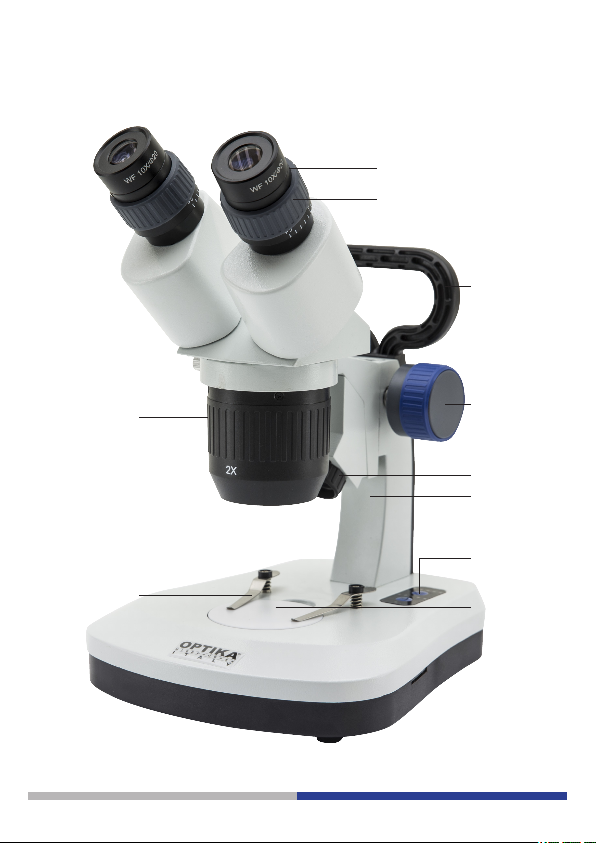
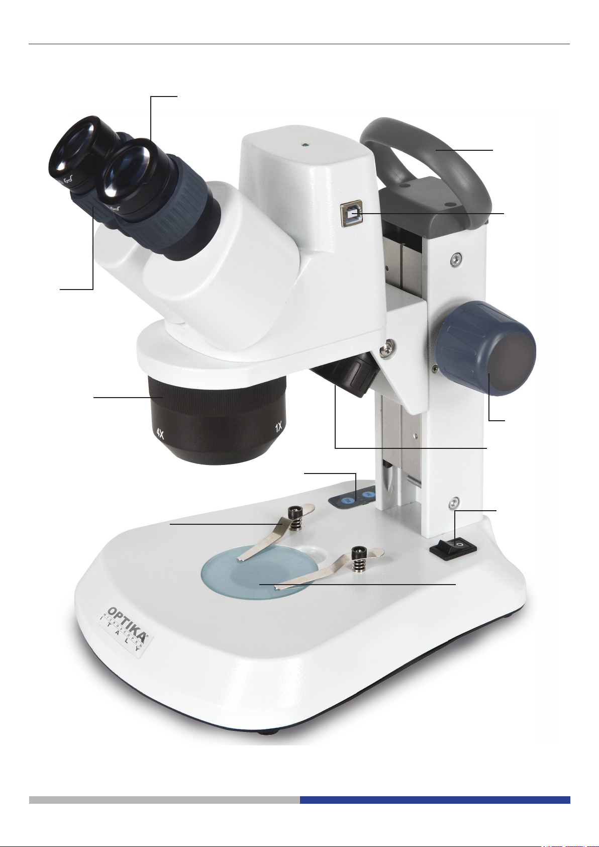
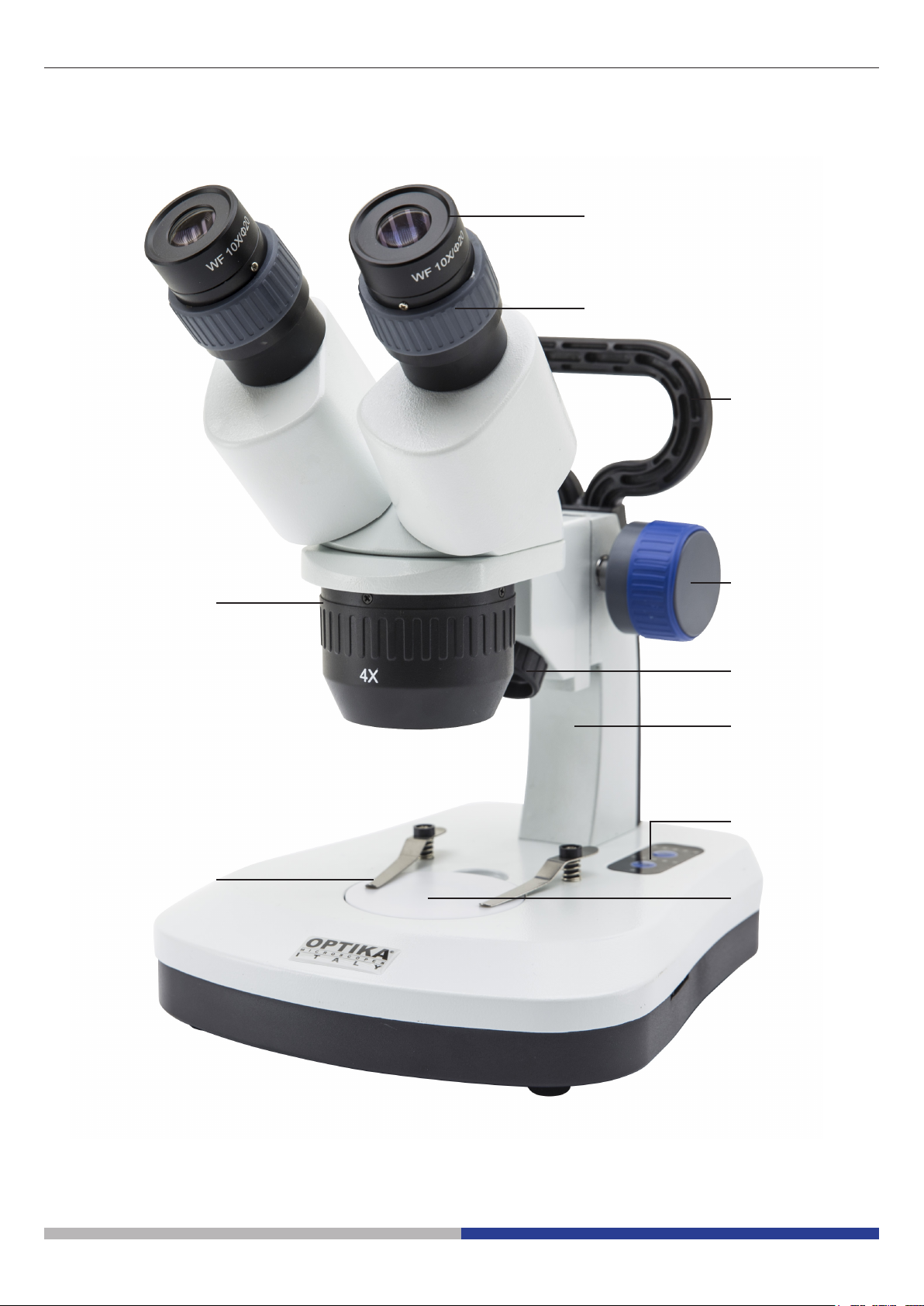
Overview SFX-33
EYEPIECES
DIOPTRIC
COMPENSATION
HANDLE
TURNABLE
OBJECTIVE
SLIDE CLAMP
FOCUS KNOB
INCIDENT LIGHT
STAND
TOUCH CONTROL
TRANSMITTED
LIGHT
Page 8

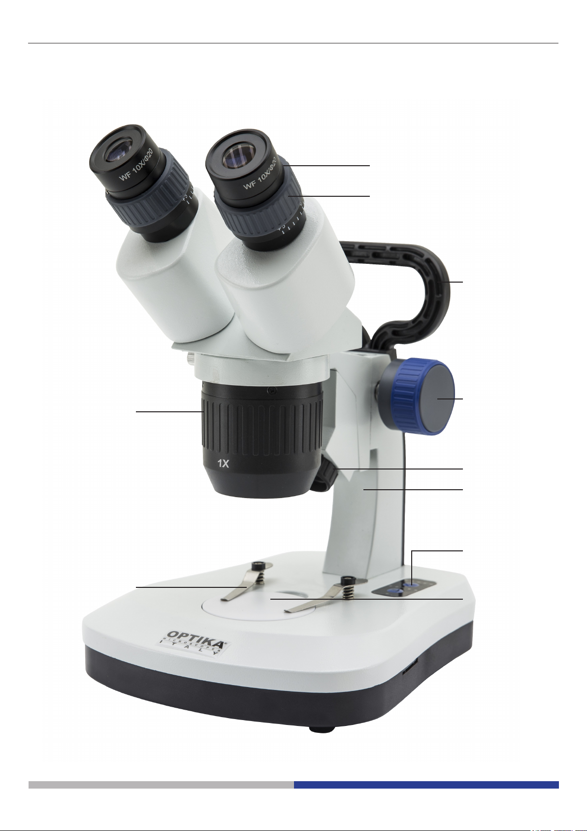
Overview SFX-34
EYEPIECES
DIOPTRIC
COMPENSATION
HANDLE
TURNABLE
OBJECTIVE
SLIDE CLAMP
FOCUS KNOB
INCIDENT LIGHT
STAND
TOUCH CONTROL
TRANSMITTED
LIGHT
Page 9
Overview SFX-51
EYEPIECES
DIOPTRIC
COMPENSATION
HANDLE
TURNABLE
OBJECTIVE
SLIDE CLAMP
FOCUS KNOB
INCIDENT LIGHT
STAND
TOUCH CONTROL
TRANSMITTED
LIGHT
Page 10
Overview SFX-52
EYEPIECES
DIOPTRIC
COMPENSATION
HANDLE
TURNABLE
OBJECTIVE
SLIDE CLAMP
FOCUS KNOB
INCIDENT LIGHT
STAND
TOUCH CONTROL
TRANSMITTED
LIGHT
Page 11
Overview SFX-91
EYEPIECES
HANDLE
DIOPTRIC
COMPENSATION
TURNABLE
OBJECTIVE
SLIDE CLAMP
TOUCH CONTROL
FOCUS KNOB
INCIDENT LIGHT
STAND
ON-OFF SWITCH
TRANSMITTED
LIGHT
Page 12
Overview SFX-91D
DIOPTRIC
COMPENSATION
EYEPIECES
HANDLE
CAMERA USB
OUTPUT
TURNABLE
OBJECTIVE
FOCUS KNOB
INCIDENT LIGHT
TOUCH CONTROL
ON-OFF SWITCH
SLIDE CLAMP
TRANSMITTED
LIGHT
Page 13
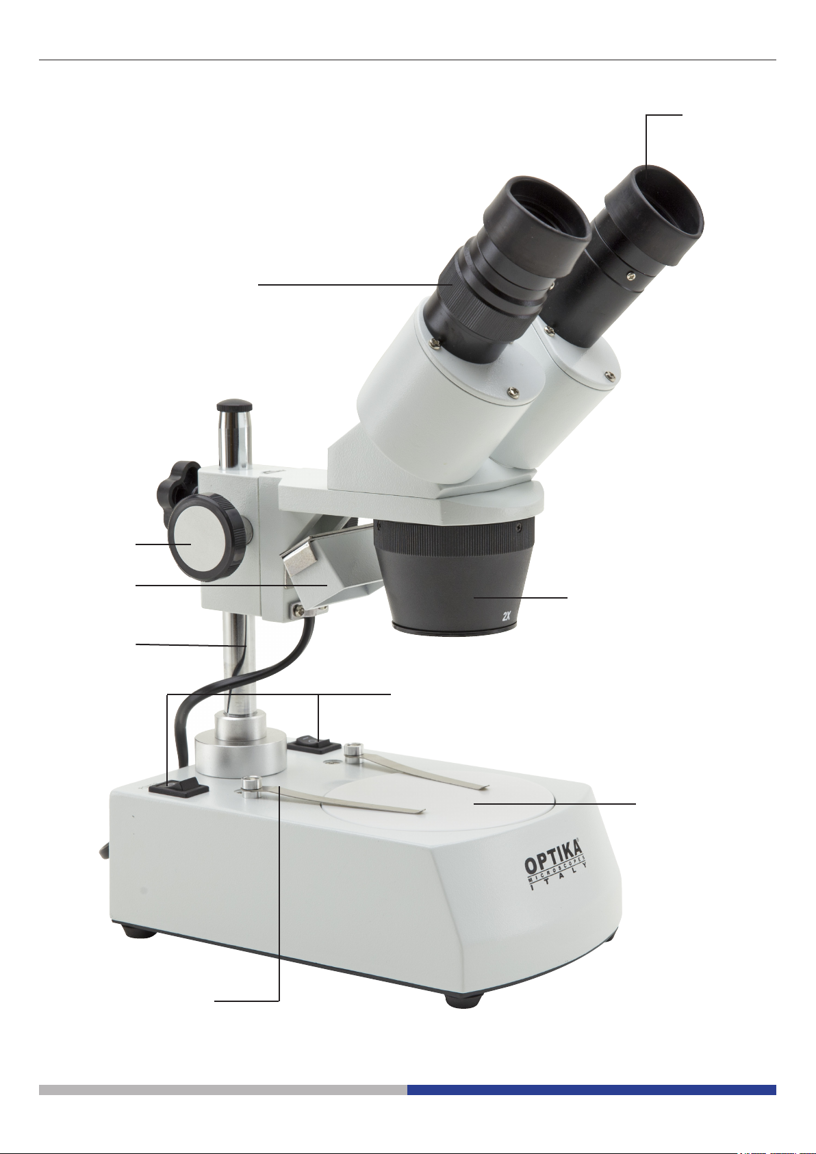
Overview ST-30FX
DIOPTRIC
COMPENSATION
EYEPIECES
FOCUS KNOB
INCIDENT LIGHT
STAND
TURNABLE
OBJECTIVE
ON-OFF SWITCH
TRANSMITTED
LIGHT
SLIDE CLAMP
Page 14
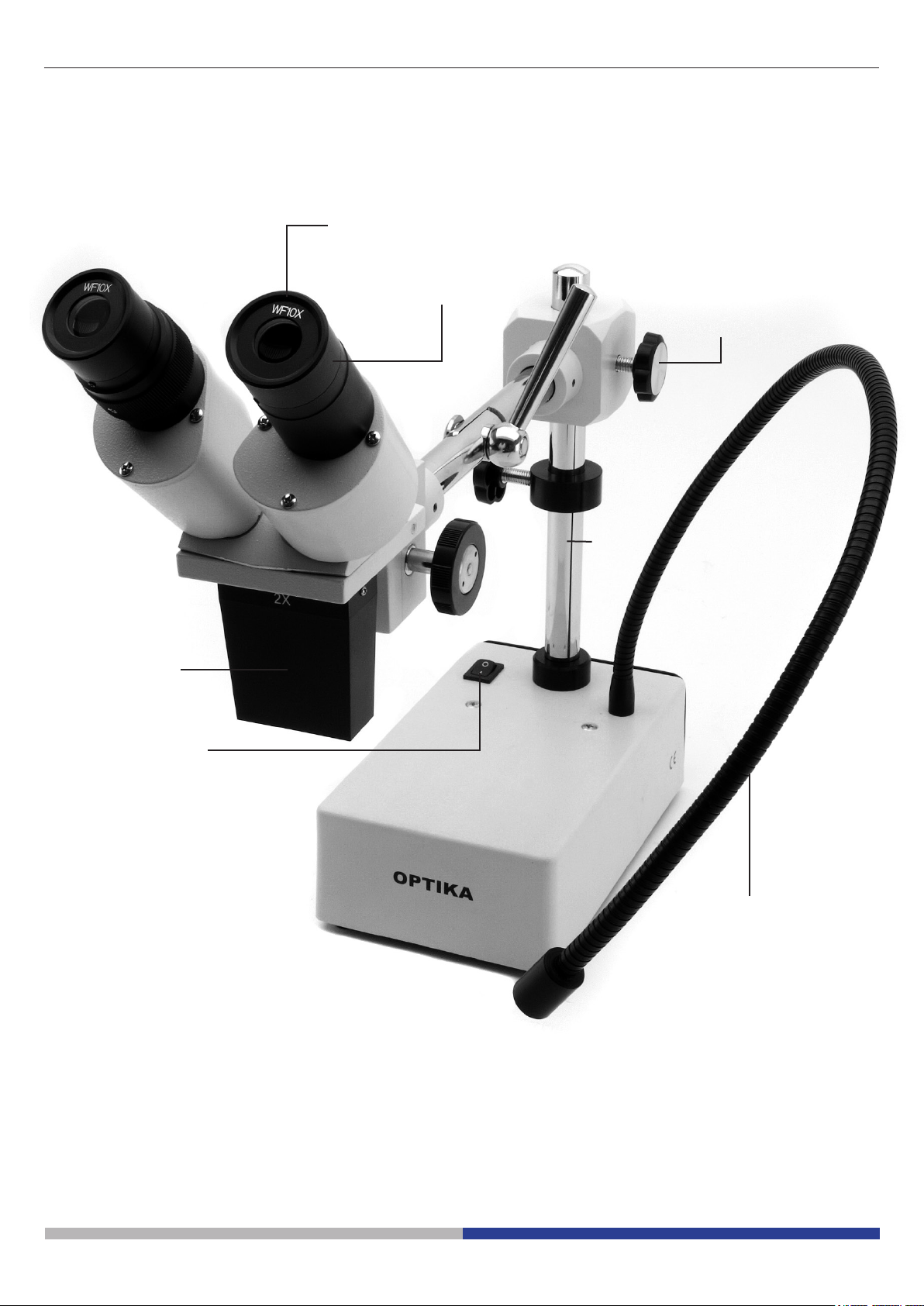
Overview ST-50Led
EYEPIECES
DIOPTRIC
COMPENSATION
FOCUS KNOB
STAND
OBJECTIVE
ON-OFF SWITCH
FLEXIBLE ARM
LED ILLUMINATOR
Page 15
Unpacking
The microscope is housed in a moulded Styrofoam container. Remove the tape from the edge of the container
and lift the top half of the container. Take some care to avoid that the optical items (objectives and eyepieces)
fall out and get damaged. Using both hands (one around the arm and one around the base), lift the microscope
from the container and put it on a stable desk.
Using the microscope
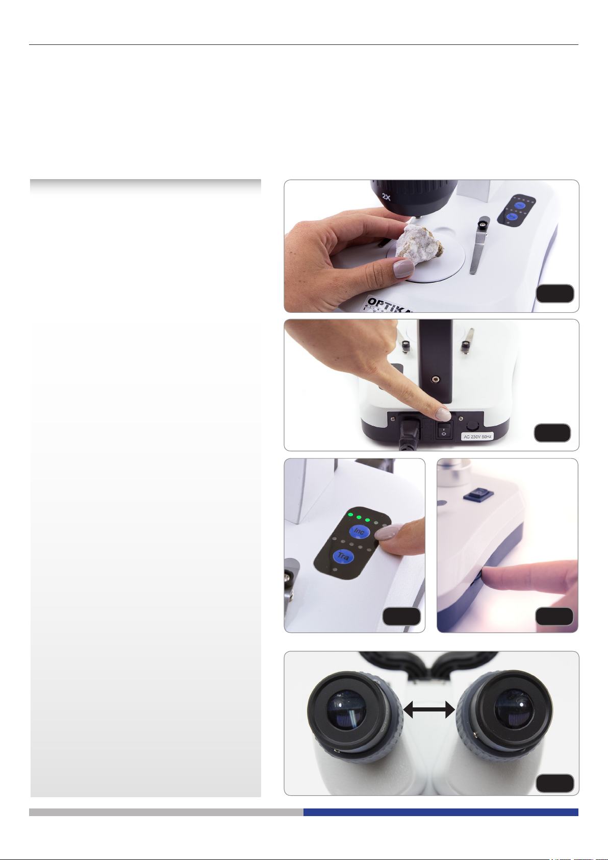
1. Place the specimen on the stage
Place the specimen on the microscope
stage and lock the specimen using the
slide-clamp if it is necessary. Ensure that
the specimen is centred over the stage
opening. (Fig.1)
Fig.1
2. Turn on the light
The microscope comes with an electrical
illuminator. Insert the plug of the cable into
the power socket, turn on the switch on the
main body and select your light source.
(Fig.2)
For SFX models, repeatedly press the
touch button in order to change the light
intensity. Depending on the model, the light
intensity can be adjusted with a knob on the
right side of the stand. (Fig.3-4)
3. Adjust interpupillary distance
Hold the right and left parts of the
observation head by both hands and
adjust the interpupillary distance by
turning the two parts until one circle of
light can be seen. If two circles appear,
the interpupillary distance is too big, and
if two overlapped circles appear, the
interpupillary distance is too small. (Fig.5)
Fig.2
Fig.3 Fig.4
Page 16
Fig.5
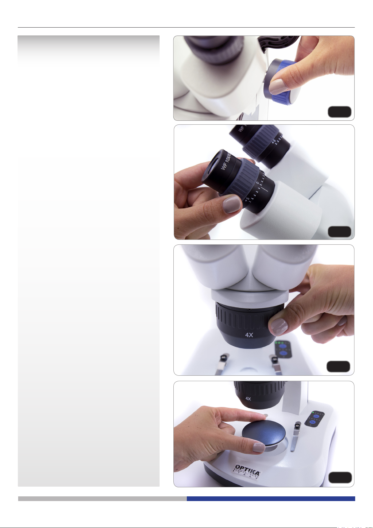
4. Focus
Rotate the focusing knob to bring the
sample into focus with the highest
magnication. (Fig.6)
5. Dioptric compensation
This compensation makes it possible
for people with glasses to adjust the
microscope to their eyes and use the
microscope without glasses. Adjust the
diopter compensation ring of the right
eyepiece tube until the image of the right
eyepiece is clear and sharp. Repeat the
procedure for the left eyepiece. (Fig.7)
Fig.6
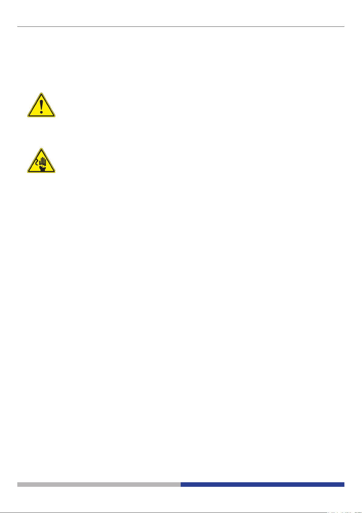
6. Magnication
Select the desired magnication by rotating
the objective. (Fig.8)
Total magnication used can be calculated
as:
Eyepiece magnication x Zoom
magnication x Objective lens
magnication.
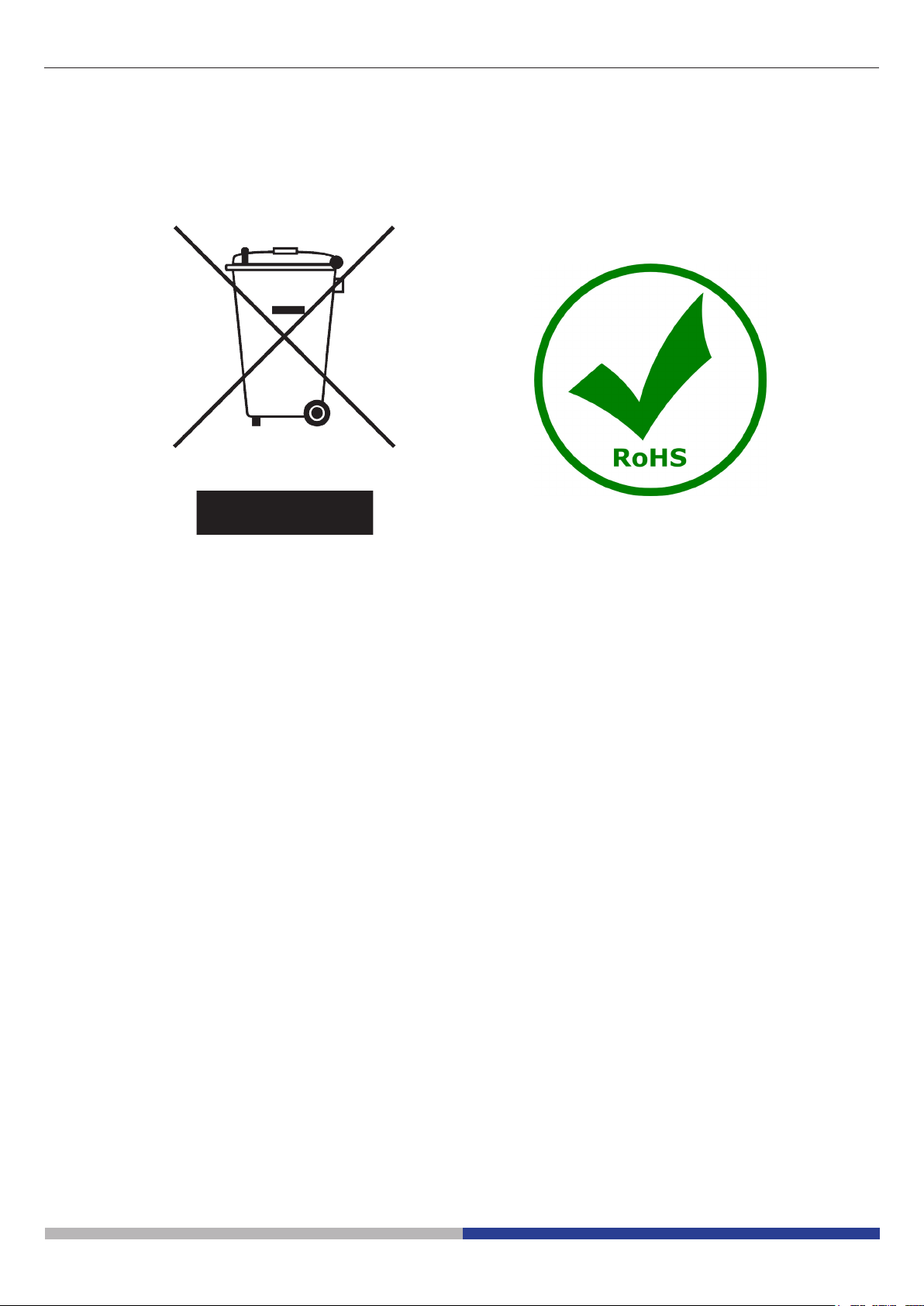
7. Contrast disc
You can use the black/white disc in order
to enhance the contrast of the image when
using the incident illumination.
If you want to look at bright opaque
objects, place the disc with the black side
up. (Fig.9)
Fig.7
Fig.8
Page 17
Fig.9

Only for SFX-91D
Installation of camera drivers and software
Operating system requirements: Windows XP, Windows 7, Windows 8 or Windows 10. If your PC is Windows
XP: before the installation of your Camera please check if Service Pack2 is installed. If not, please update your
XP from the Microsoft web site. If your PC has a USB port less than 2.0, there may be some problems in capturing image from the camera due to the slow transmission.
1. Please insert your CD and run:
\optika vision lite \ setup.exe
2. Now Optika Vision Lite icon appears on your desktop.
3. Open the folder “\drivers” and run all the “.exe” les.
4. The installer may show warnings about missing Windows certication: ignore such warnings and select
“Continue”. Note : do NOT cancel the installation.
5. At the end of the installation process restart the PC if requested.
6. Plug the Camera in your PC: the camera will be identied and Windows will recognize the driver which
has just been installed from the CD.
Then ignore any message about Windows compatibility and select “Continue” .
Note : do NOT cancel the installation.
7. At the end of the identication process, disconnect your Camera and try to plug it again, in order to check
if the Driver was installed correctly (no Windows error messages should appear).
Should any error message appear on your PC, you will nd a “\Troubleshooting” folder on your CD which
shows how to solve any problem which Windows could give.
Some notes
You should know that your Windows PC needs to install a Driver before capturing images from the camera:
after installing the driver from the CD, Windows needs to recognize the camera before using it.
Often a PC has some ports on the front and some on the back: the ports on the back are usually faster. We
suggest to use these ones.
All our cameras, even though they may have an external connection, do not need any external power supply
because it comes from the USB cable of your PC.
If you connect the camera into another USB port, Windows needs to recognize its Driver again even if it has
alredy done this operation for the rst USB port.
Generally, every time you use a peripheral device and after that you connect your Camera, then Windows
needs to recognize the Driver again.
Page 18

It may happen sometimes that Windows doesn’t recognize a Camera using one of your PC USB ports, while
gives no problem using another port.
To prevent any installation problem we have put on the CD all the software and drivers in specic folders with
an appropriate names.
How to test your Camera
In order to check if your Camera works correctly, it’s not necessary to put it into the microscope: it’s enough to
connect it into the USB port, run Vision Lite using the icon on your desktop, select the right driver and check
whether the shown image is not totally black.
Select the right drivers
It’s very easy:
OPTIKA TCD 3.0
With Optika Vision Lite you have to tell the Software which is the Driver by selecting the microscope-shaped
icon.
Getting started with Optika Vision Lite, a very easy measuring and documentation
software.
Run Optika Vision Lite by clicking on its icon on your desktop.
Select the right Driver for capturing the image. Note that after choosing the driver and before capturing the image
you can set the brightness, saturation, gamma ecc..
Then you can capture the image.
The image is now ready for being manipulated using Optika Vision Lite.
Page 19
Maintenance
Microscopy environment
This microscope is recommended to be used in a clean, dry and shock free environment with a temperature of
5°-40°C and a maximum relative humidity of 75 % (non condensing). Use a dehumidier if needed.
To think about when and after using the microscope
• The microscope should always be kept vertically when moving it and be careful so that no
moving parts, such as the eyepieces, fall out.
• Never mishandle or impose unnecessary force on the microscope.
• Never attempt to service the microscope yourself.
• After use, turn o the light immediately, cover the microscope with the included
dust-cover, and keep it in a dry and clean place.
Electrical safety precautions
• Before plugging in the power supply, make sure that the supplying voltage of your region
matches with the operation voltage of the equipment and that the lamp switch is in o-
position.
•
Users should observe all safety regulations of the region. The equipment has acquired
the CE safety label. However, users do have full responsibility to use this equipment safely.
Cleaning the optics
• If the optical parts need to be cleaned try rst to: use compressed air.
• If that is not sucient: use a soft lint-free piece of cloth with water and a mild detergent.
• And as a nal option: use the piece of cloth moistened with a 3:7 mixture of ethanol and ether.
Note: ethanol and ether are highly ammable liquids. Do not use them near a heat source, near sparks or
near electric equipment. Use these chemicals in a well ventilated room.
• Remember to never wipe the surface of any optical items with your hands. Fingerprints can damage the
optics.
• Do not disassemble objectives or eyepieces in attempt to clean them.
For the best results, use the OPTIKA cleaning kit (see catalogue).
If you need to send the microscope to Optika for maintenance, please use the original packaging.
Page 20
Equipment disposal
Art.13 Dlsg 25 july 2005 N°151. “According to directives 2002/95/EC, 2002/96/EC and 2003/108/EC relating
to the reduction in the use of hazardous substances in electrical and electronic equipment and waste disposal.”
The basket symbol on equipment or on its box indicates that the product at the end of its useful life should be
collected separately from other waste.
The separate collection of this equipment at the end of its lifetime is organized and managed by the producer.
The user will have to contact the manufacturer and follow the rules that he adopted for end-of-life equipment
collection.
The collection of the equipment for recycling, treatment and environmentally compatible disposal, helps to prevent
possible adverse effects on the environment and health and promotes reuse and/or recycling of materials of the
equipment.
Improper disposal of the product involves the application of administrative penalties as provided by the laws in force.
Page 21


Serie SFX/STEREO
MANUALE D’ISTRUZIONI
Modello
MS-2
STX
SFX-31
SFX-32
SFX-33
SFX-34
SFX-51
SFX-52
SFX-91
SFX-91D
ST-30FX
ST-50Led
v 1.3 2017

Avvertenza
Questo microscopio è uno strumento scientico di alta precisione, progettato per durare a lungo con una minima
manutenzione; la realizzazione è secondo i migliori standard ottici e meccanici, per poter essere utilizzato
quotidianamente. Vi ricordiamo che questo manuale contiene informazioni importanti per la sicurezza e per la
manutenzione dello strumento, e deve quindi essere messo a disposizione di coloro che lo utilizzeranno.
Decliniamo ogni responsabilità derivante da un utilizzo dello strumento non indicato nel presente manuale.
Simboli
La seguente tabella riporta i simboli utilizzati in questo manuale.
PERICOLO
Questo simbolo indica un rischio potenziale ed avverte di procedere con cautela.
SHOCK ELETTRICO
Questo simbolo indica un rischio di shock elettrico.
Informazioni sulla sicurezza
Per evitare shock elettrici
Prima di collegare il cavo di alimentazione alla presa elettrica, assicurarsi che il voltaggio della rete locale
coincida con il voltaggio dello strumento e che l’interruttore dell’illuminazione sia nella posizione “O”.
Gli utenti dovranno seguire tutte le norme di sicurezza locali. Lo strumento è certicato CE. In ogni caso, gli
utilizzatori sono gli unici responsabili per un utilizzo sicuro dello strumento. Per l’utilizzo in sicurezza dello
strumento è importante attenersi alle seguenti istruzioni e leggere il manuale in tutte le sue parti.
Utilizzo previsto
Solo per ricerca. Non è previsto alcun utilizzo di questo strumento per uso diagnostico.
Pagina 25
Descrizione dello strumento MS-2
OCULARE
TESTA
OBBIETTIVO
MANOPOLA DI
MESSA A FUOCO
PINZETTE FERMA
VETRINI
Descrizione dello strumento STX
OCULARE
TESTA
OBBIETTIVO
MANOPOLA DI
MESSA A FUOCO
PINZETTE FERMA
VETRINI
Pagina 27
Descrizione dello strumento SFX-31
OCULARI
COMPENSAZIONE
DIOTTRICA
MANOPOLA DI
MESSA A FUOCO
OBIETTIVO
ROTANTE
PINZETTE FERMA
VETRINI
LUCE INCIDENTE
STATIVO
PULSANTE
ON-OFF
LUCE TRASMESSA
REGOLAZIONE
DI INTENSITÀ

Descrizione dello strumento SFX-32
OCULARI
COMPENSAZIONE
DIOTTRICA
MANOPOLA DI
MESSA A FUOCO
OBIETTIVO
ROTANTE
PINZETTE FERMA
VETRINI
LUCE INCIDENTE
STATIVO
PULSANTE
ON-OFF
LUCE TRASMESSA
REGOLAZIONE
DI INTENSITÀ
Pagina 29
Descrizione dello strumento SFX-33
OCULARI
COMPENSAZIONE
DIOTTRICA
MANIGLIA
OBIETTIVO
ROTANTE
PINZETTE FERMA
VETRINI
MANOPOLA DI
MESSA A FUOCO
LUCE INCIDENTE
STATIVO
CONTROLLO
LUMINOSITÀ A
TASTIERA
LUCE TRASMESSA
 Loading...