

Page 1

INSTRUCTION MANUAL
Model
IS-01
INSPECTION SYSTEMS Series
Version: 1
Issued: 1.0.0
Page 2

IS-01
Compact Inspection Video Microscope
INSTRUCTIONS
This instruction manual is for the operation guide, troubleshooting and maintenance to IS-01 compact
Inspection Video Microscope. Please study this manual thoroughly before operating, and keep it with the
instrument. The manufacturer reserves the rights to the modifications by technology development.
On the basis of operation ensured, technical specifications may be subject to changes without notice
Pag. 2
Page 3

Contents
Hardware
1. Getting Ready 4
1.1 Operation 4
1.2 Maintenance 4
1.3 Components 5
2. Assembling 7
2.1 Assembling Scheme 7
2.2 Assembling Steps 8
3. How to Use 11
3.1 Adjust the Focusing Tension 11
3.2 Set Illumination 11
3.3 Place the Specimen 12
3.4 Adjust the Focus 12
3.5 Lock the Magnification 12
3.6 Use the Button and Interface 13
4. Troubleshooting 14
5. Optical Data 15
Software
6. Overview 16
6.1 Software Start and Quit 16
6.1.1 Software Start 16
6.1.2 Software Quit 16
6.2 Main Commands 17
6.2.1 Command introduction 17
6.2.2 Command’s icon introduction 17
7. Operation Instructions 19
7.1 Local browse 19
7.2 Colour and exposure adjustment 19
7.2.1 Exposure Adjustment 20
7.2.2 Colour Adjustment 20
7.3 Calibration 20
7.4 Drawing mark tool 25
7.5 AWB (Automatic White Balance) 26
7.6 WDR Function 26
7.7 Setting Button 27
7.8 Image real-time transmission 28
7.8.1 WiFi transmission 28
7.8.2 USB Transmission 30
7.9 Image / Video Switch 31
7.9.1 Image function 31
7.9.2 Video Function 31
7.10 Zoom Picture 32
8 Troubleshooting 33
Pag. 3
Page 4

1 Getting Ready
1.1 Operation
1) Do not expose the microscope in the sun directly. The microscope ought to be placed where is dry and
clean. Avoid high temperature and violent vibration.
2) As the microscope is a high precision instrument, always operate it with care, and avoid physical shock or
crash during the transportation.
3) To keep the image clear, please do not leave fingerprints or stains on the surfaces of lens.
4) Never rotate the left and right focusing knobs in reverse direction; otherwise the microscope will be
damaged.
1.2 Maintenance
1) Keep all the surface of the lens clean. Wipe the lens gently with a soft lens tissue or blow away the dust.
Carefully wipe off oil or fingerprints on the lens surfaces with tissue moistened with a little of 3:7 mixture of
alcohol and ether.
2) Do not use organic solution to wipe the surface of other components, especially the surface of plastic
components. Please use the neutral detergent if necessary.
3) Never disassemble the microscope yourself, otherwise it will influence its function or damage it.
4) After using, cover the microscope with a dust cover to prevent it from the dust, and store it in a place free
from moisture to avoid rusting.
To keep the performance of the microscope, please check it periodically. For more details, please contact the
agents nearby.
Pag. 4
Page 5

knobs
1.3 Components
Display
Microscope
body
HDMI connector
Magnification
changer
LED
ringlight
Microscope
stand
MINI connector
USB connector
Video button
Image button
Power switch
Coarse focus
knob
LED light
adjustment
Pag. 5
Page 6

input
SD card slot
Power
supply
Lock for
magnification
changer
Pag. 6
Page 7
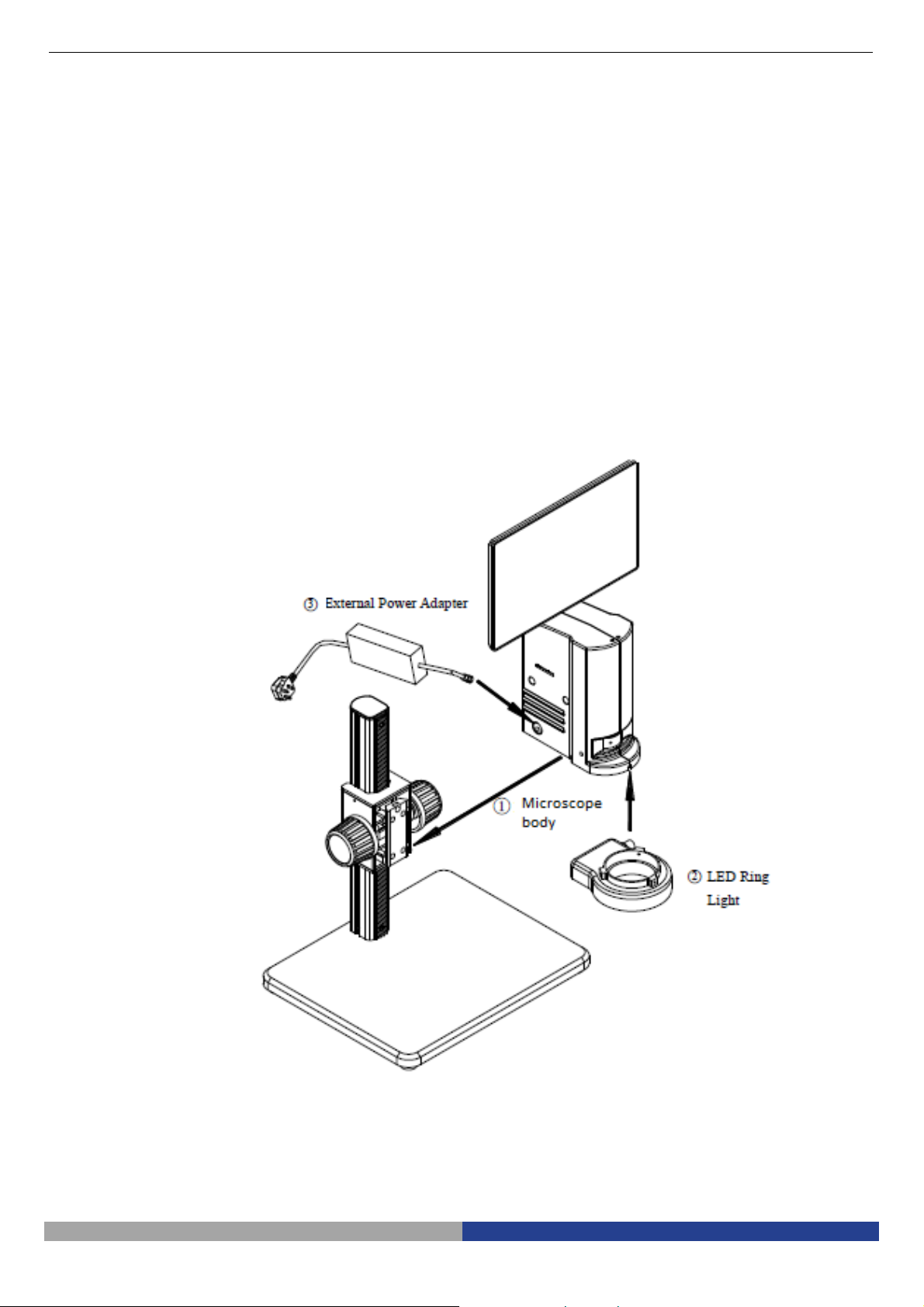
2. Assembling
2-1 Assembling Scheme
Below is the Assembling Scheme to describe how to assemble the components, and the numbers denote the
assembling order.
Before assembling, make sure there is no dust, dirt or other materials which will disturb it.
Assemble carefully and do not scrap any part or touch the glass surface.
Preserve the hexagon spanner, and it will be used when changing the parts.
Pag. 7
Page 8
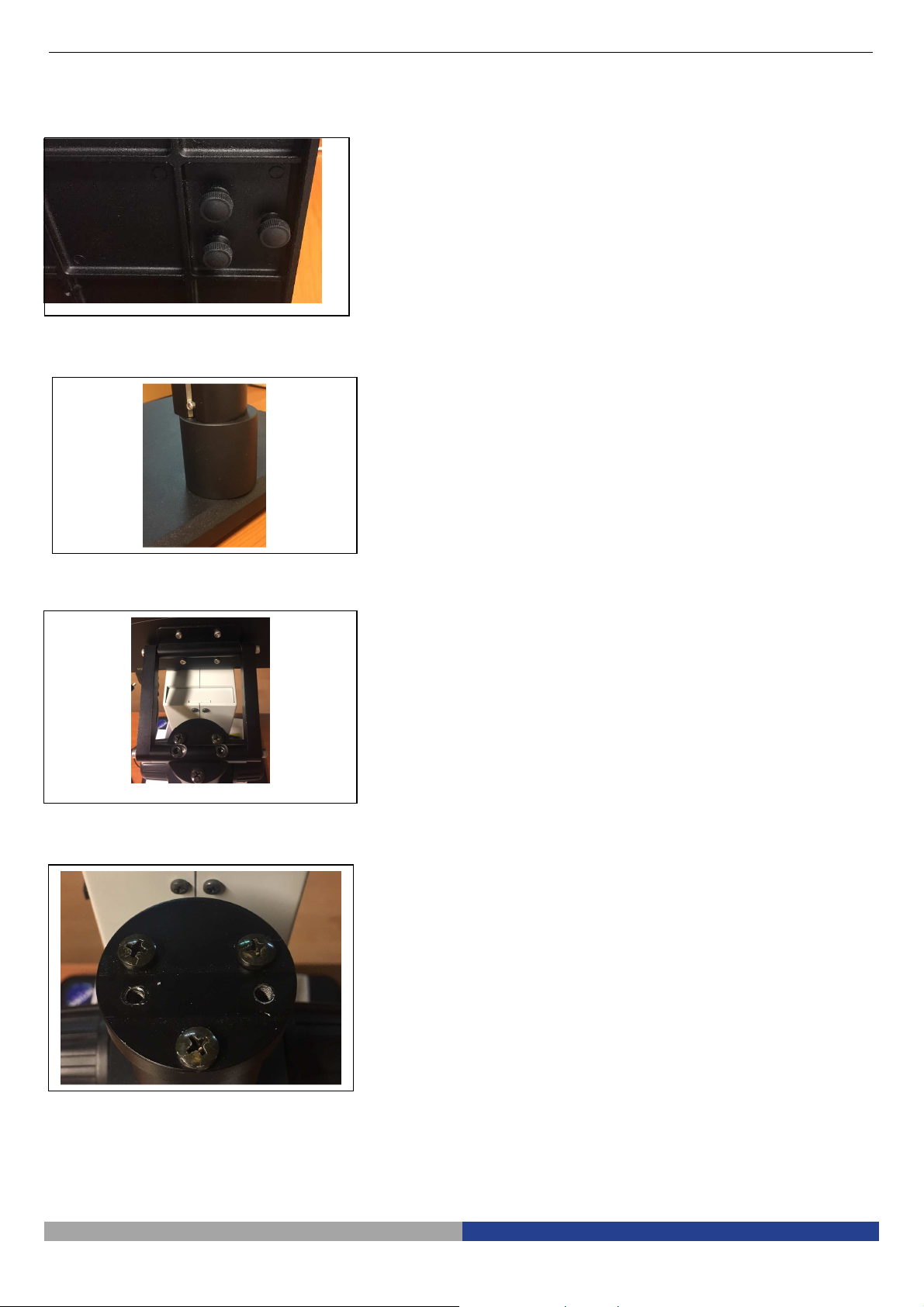
2-2-1
Assemble the extension ring (Fig. 1
-
2)
2-2-2
Assemble the HDMI monitor (fig.3
-
4)
2.2 Assembling Steps
Fig. 1
Fig. 2
Fig. 3
1. Unscrew the three screws on the bottom of
the stand in order to remove the microscope
arm.
2. Install the extension ring on the stand, then
reinstall the microscope arm.
• The extension ring is used to increase the
length of the microscope arm, thus
increasing the working distance.
1. Unscrew the three screws on the top of the
microscope arm, then remove the cap.
2.
Install the provided cap by screwing the
three screws
.
3. Install the rectangular HDMI monitor holder
using the two provided screws.
4. Assemble the HDMI monitor on the
rectangular bracket using the provided
screws.
Fig. 4
Pag. 8
Page 9
2-2-3
Assemble the Microscope Body (Fig.
2-2-4
Assemble the LED Ring Light
(Fig. 6)
2-2-5
Connect the Power Cord (Fig. 7)
5)
1. Match the dovetail interface ① of the
microscope body with the dovetail groove
② of the focus bracket group, and insert it
from top to bottom as the direction shown
in the figure.
2. Tighten the M4 inner hexagon screw on the
body group ③ with a M4 inner hexagon
spanner (side length 2mm).
Fig. 5
1. Move the LED right light close to the
microscope body according to the
arrowhead direction, align the three screw
holes ① with the thread groove ②, and
lock the screw with a M4 inner hexagon
spanner(side length 2mm).
Fig. 6
1. Insert the external adapter plug ① into the
power supply adapter socket ② of the
microscope body to the bottom, and the
power will be switched on.
Don’t use excessive force when the
power cord is bended or twisted,
otherwise it will be damaged.
Use the special wire supplied by our
company. If lost or damaged, choose an
external power adapter with the same
Fig. 7
specifications (power cord/charger).
Pag. 9
Page 10

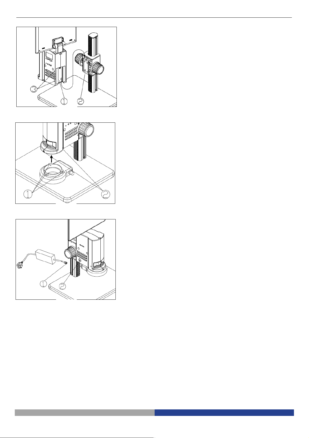
2-2-6 Installing Additional lenses
(Fig. 8
-9-
Fig. 8
10)
It is possible to install any of the available
additional lenses (0.5x or 1.4x). To do this,
please follow these steps:
1. Remove the LED ring light from the bottom
of the microscope body. (Fig. 8)
2.
Using the provided Allen wrench, loosen
the screws placed on the front, on the right
and on the left sides of the microscope
body, in order to remove the LED ring light
holder.(Fig. 9)
Fig. 9
Fig. 10
3. Unscrew the existing lens installed on the
microscope and replace with the desired
additional lens. (Fig. 10)
4. Reverse the disassembly procedure to
reinstall the removed parts.
Pag. 10
Page 11
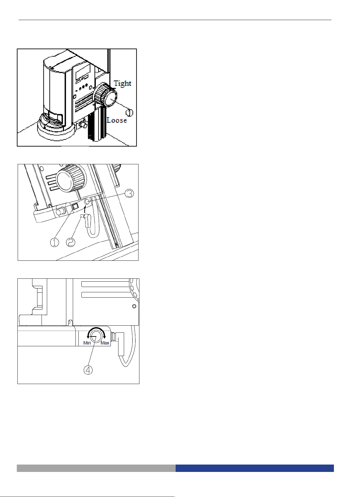
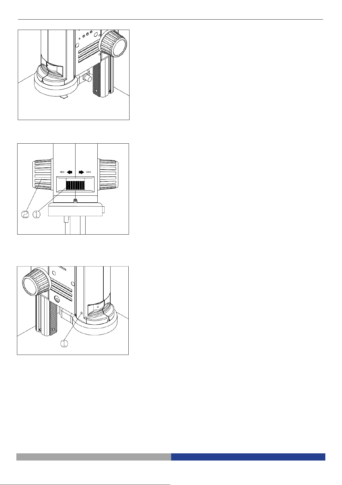
3-1
Adjust the Focusing Tension (Fig. 11)
3-2
Set Illumination (Fig. 12
-
13)
3. How to Use
1. To adjust the focusing tension, grip the left
knob and rotate the right knob ①. It will be
tighten when rotated in clockwise, while
loosen in counter-clockwise.
2.
Adjust the focusing tension to appropriate
position, to prevent the microscope body
declining with the bracket when observing,
and also make focusing more comfortable
.
Fig. 11
1. Insert the power cord plug ② of body
group into the ring light interface ③, then
turn on the switch ① to start the light
source.
Fig. 12
2.
Rotate the light adjustment knob to
adjust the illumination brightness.
Fig. 13
Pag. 11
Page 12
3-3
Place the Specimen (Fig. 14)
3-4
Adjust the Focus (Fig. 15)
3-5
Lock the Magnification (Fig. 16)
Fig. 14
1.
Put the specimen on the base and let the
observation point exactly below the
microscope.
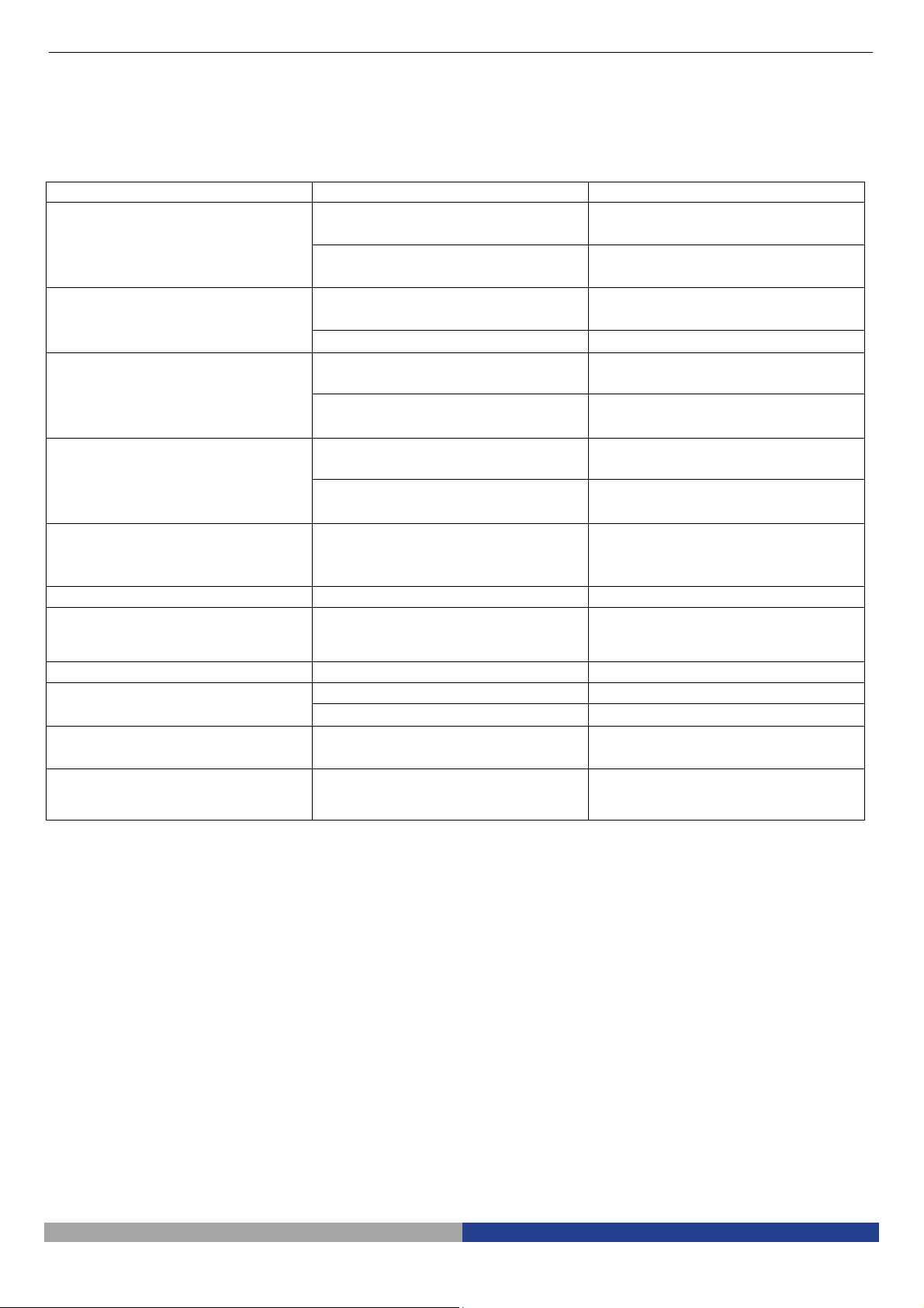
1. Rotate the zoom adjustment ring ① to
the maximum magnification.
2. Observe the output image, if it is not
clear, rotate the focusing knob ② to
make it sharp.
3. Rotate zoom adjustment ring to the
minimum magnification. Observe the
output image until it is clear.
High low magnification parfocality is set
to best position when this product is
produced.
Fig. 15
Fig. 16
1. If use a fixed magnification for long term
or use with shake, tighten and fix the
magnification lock-screw ① with a M4
inner hexagon spanner (side length
3mm).
Pag. 12
Page 13

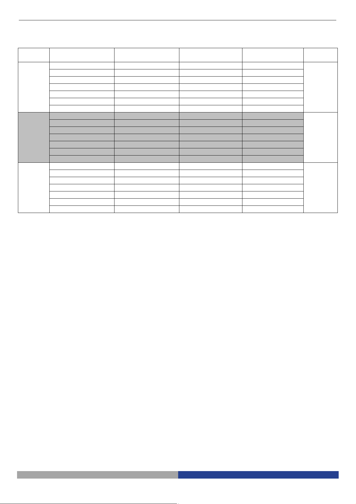
3-6
Use the Button and Interface (Fig. 17
-
Fig. 17
18)
1. Press the ON-OFF key ① for 3-5 seconds,
the indicator ⑦ will turn from orange to
green, which means the microscope is
starting up.
It means the camera is working when
the indicator flashes.
2. Camera button ②: when the camera is
working, press once to capture picture.
3. Video button ③: when the camera is
working, press down for the first time to
start recording, and press again to end
recording.
4. HDMI cable interface④, connect the HDMI
cable to output the high definition image
signal.
5. USB interface ⑤: connect the USB cable
with the devices as mouse and USB disk.
6. MINI interface ⑥: connect the MINI cable
to output the USB function image.
7. SD card is as shown in the figure, face the
chamfer to the left and insert it to the
bottom. (Fig. 18)
Fig. 18
Pag. 13
Page 14
Problem
Cause
Solution
4. Troubleshooting
As the performance of microscope cannot play fully due to unfamiliar operations, the table below can provide
some solutions.
1) Stain or dust is observed in the
video.
2) The video image is unclear. Stains have accumulated on the lens
3) The video image doesn’t display The power switch is not ON. Turn on the switch button of
Stains have accumulated on the
specimen
Stains have accumulated on the CCD
surface.
surface.
Focusing is not correct. Adjust the focusing.
The external power cable is not well
connected.
Clean the specimen.
Clean the CCD surface.
Clean the lens.
microscope body.
Check cable connections.
4) The image is too bright or too
dark.
5) The display is no responding
and flashes back.
6) The focus knob is not flexible The focusing knob is too tight. Loosen the focusing knob
7) The image is not clear due to
the dropping of the microscope
body.
8) Microscope body cannot zoom The zoom adjustment ring is locked. Loosen the lock-screw
9) LED does not lights up when
powered on.
10) LED light is burnt out suddenly. Voltage is too high. Use a suitable external power
11) The illumination brightness is
not enough.
The LED ring light illumination has a
wrong setting.
Display properties setting Open the display settings menu to
Too many operations in the same
time and some disorder, which
results in error feedback of system.
The focusing knob is too loose. Tighten it.
No power. Check cable connections
The LED light is burnt out Replace with a suitable light source.
Voltage is too low. Use a suitable external power
Adjust the brightness of LED ring
light.
adjust the brightness.
Restart it.
adapter.
adapter.
Pag. 14
Page 15
5. Optical Data
Objective Optical Magnification On-Screen
Magnification
0.5x
1x
1.4x
Calculation done on 11,5” HDMI screen
0.35x 8.4x 26 16
0.5x 12x 18.2 11.2
0.75x 18x 12.12 7.4
1x 24x 9.1 5.6
1.5x 36x 6.06 3.72
2x 48x 4.54 2.8
2.5x 60x 3.64 2.24
0.7x 16.8x 13 8
1x 24x 9.1 5.6
1.5x 36x 6.06 3.7
2x 48x 4.55 2.8
3x 72x 3.03 1.86
4x 96x 2.27 1.4
5x 120x 1.82 1.12
0.98x 23.52x 9.28 5.71
1.4x 33.6x 6.5 4
2.1x 50.4x 4.33 2.64
2.8x 67.2x 3.25 2
4.2x 100.8x 2.16 1.32
5.6x 134.4x 1.62 1
7x 168x 1.3 0.8
Horizontal Field of
View (mm)
Vertical Field of
View (mm)
W.D.
(mm)
170
135
100
Pag. 15
Page 16
6. Overview
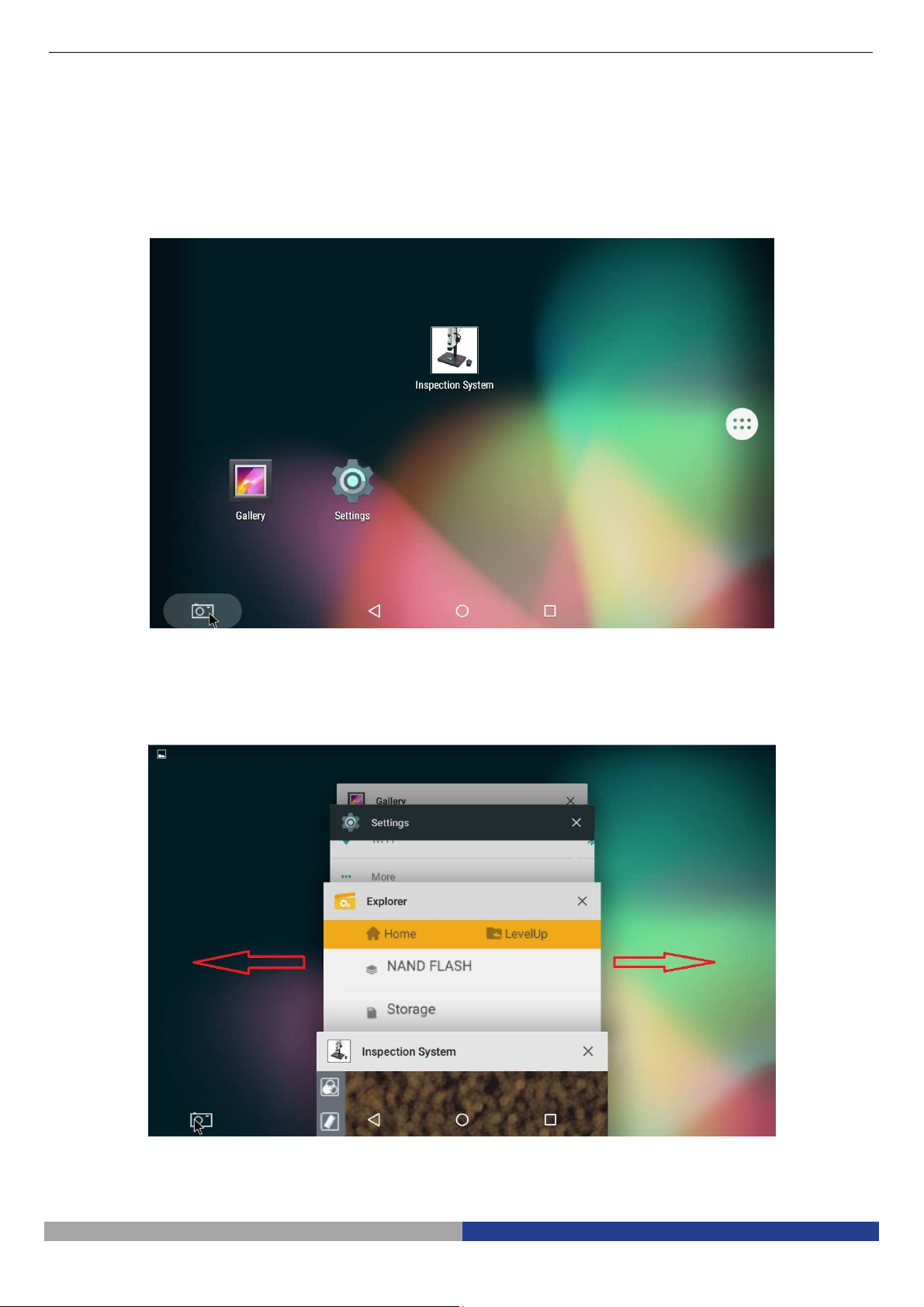
6.1 Software start and quit
6.1.1 Software Start
Click the icon application in the main menu to start.
6.1.2 Software Quit
Click the background button, all opened software in android system will be appeared.
If need to quit, just click the exit button “X” in the top right corner of this software. Or gently swipe to the left or right to exit the program.
Pag. 16
Page 17

6.2 Main Commands
6.2.1 Command introduction
Start the program. Once started the program shows the following screen:
6.2.2 Commands icon introduction
A brief introduction to the current default icons:
: Local browse
: Colour and exposure adjustment
: Drawing mark tool
: White balance lock
: WDR
Pag. 17
Page 18
: WiFi output hotkeys
: USB output hotkeys
: Settings
: Image / video switch hotkeys
: Image zoom
Pag. 18
Page 19
7 Operation Instructions
7.1 Local browse
Click on the button in the left menu bar, will jump to the local gallery. Click on the corresponding folder to
view and edit the pictures and videos files: (delete images, colour effect transformation, etc.)
7.2 Colour and exposure adjustment
Click on the button in the left menu bar, will pop up a translucent view window in the main screen, including
exposure adjustment and colour adjustment, as shown in the figure:
Exposure Adjustment Colour Adjustment
Pag. 19
Page 20
7.2.1 Exposure Adjustment
Exposure adjustment region can select the exposure mode, Manual or Automatic exposure
(AutoExposureLock “OFF” or “ON”) , Exposure Compensation
,Gain ,Integration Time
.
7.2.2 Colour Adjustment
Colour adjustment region affects the visual contrast adjustment under the different content through the
microscope.
Colour adjustment includes brightness , contrast ,
saturation , chrominance .
7.3 Calibration
In order to perform precise measurements, a system calibration is needed.
Click on the ruler button . A window will appear:
Click on “Edit” button
A new window will appear.
Pag. 20
Page 21
Click on “Edit” and a new window appears:
Now put a ruler or a known reference under the microscope and focus.
Click on “Add”:
Pag. 21
Page 22
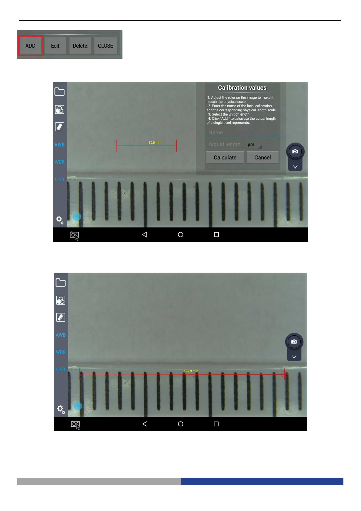
A new window will appear:
Move the red marker on the ruler
and then click on “Name”
Pag. 22
Page 23

An input dialog will appear where the user must input the actual magnification:
Insert the magnification (e.g. 0,7x) and click on “Next”.
Another input dialog will prompt to insert the length of the red marker (e.g. 12 mm)
Pag. 23
Page 24

Click on “DONE”.
You will return to the previous dialog.
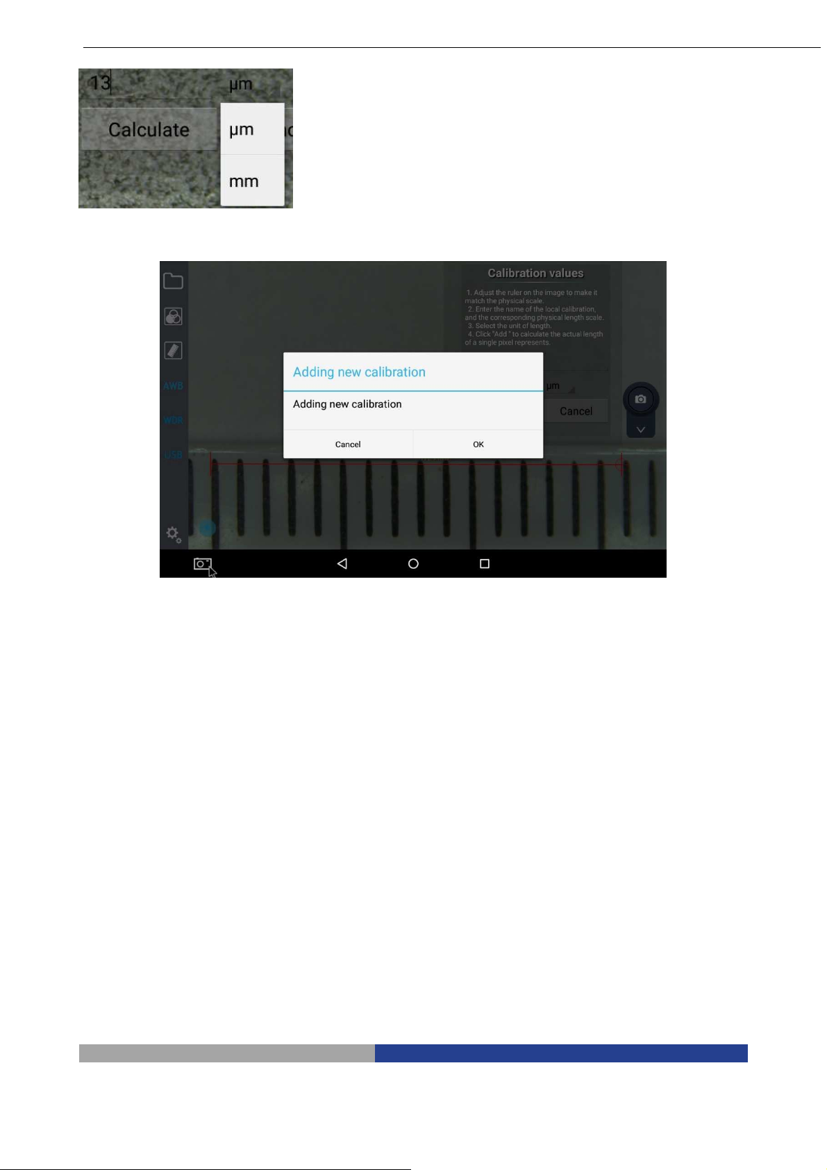
Now select the unit (µm or mm)
At the end of all the operations click on “Calculate”. A dialog will appear:
Pag. 24
Page 25

Press “OK” and the first calibration point has been saved.
Now repeat all these steps for each magnification of the microscope.
When all the magnifications will be calibrated, the calibration list will be available:
Before performing any measurement, it is important to open the related calibration according to the
magnification in use.
7.4 Drawing mark tool
On the displayed images the user can have many useful function.
These can be activated by clicking the ruler button .
Click on drawing mark tool button on the left menu bar, and then many kinds of drawing marker will appear in
the top right of frame.
Commands are the following: point , straight line , rectangle , circle , concentric circle ,
center distance , cross line , perpendicular line , angle , text , delete single item (delete last
step or delete after mark) ,delete all .
Pag. 25
Page 26

By clicking the line with mark , or character colour ,another option window will appear showing a
colour palette with six colours (yellow, black, white, green, red and blue)
.
By selecting one of these colours will change the colour of the selected item. When use image function, the
user can save the marked picture into the local folder along with the image (the marked video will not be saved
when recording).
The effect of drawings on the image can be like this:
Once the system is calibrated, the user can select the unit for the displaying of the drawn lines (microns,
millimeters, and so on)
7.4 AWB (Automatic White Balance)
Click on the button on the left menu to start AWB (Automatic White Balance).
When an image is taken under fluorescent bulb, it will appear with a greenish tinge; under halogen light it will be
yellowish, while under sun light takes a blue tinge: the reason lies in the setting of "white balance".
The role of the white balance is to recover the images’ normal colour in these scenes.
AWB is based on image algorithm, so when you start the automatic white balance with the microscope, you should
choose white areas to establish the “white”.
Put a white paper under the microscope: the system will automatically calculate the colour temperature and the
results of the correction is that the image's average colour is white.
7.5 WDR Function
WDR, acronym for Wide Dynamic Range, means that brightest and darkest parts of the image can be
observed clearly at the same time. When WDR function is activate, system will improve the brightness of too
dark area, especially under the stereomicroscope. Click on the button on the left menu bar, the button will
Pag. 26
Page 27

change to , and there is a prompt message for opening the WDR function in the center of the screen
.
WDR function is active
WDR function is not active
7.7 Setting Button
To open the setting function, click on button: a translucent window appears as shown:
Pag. 27
Page 28
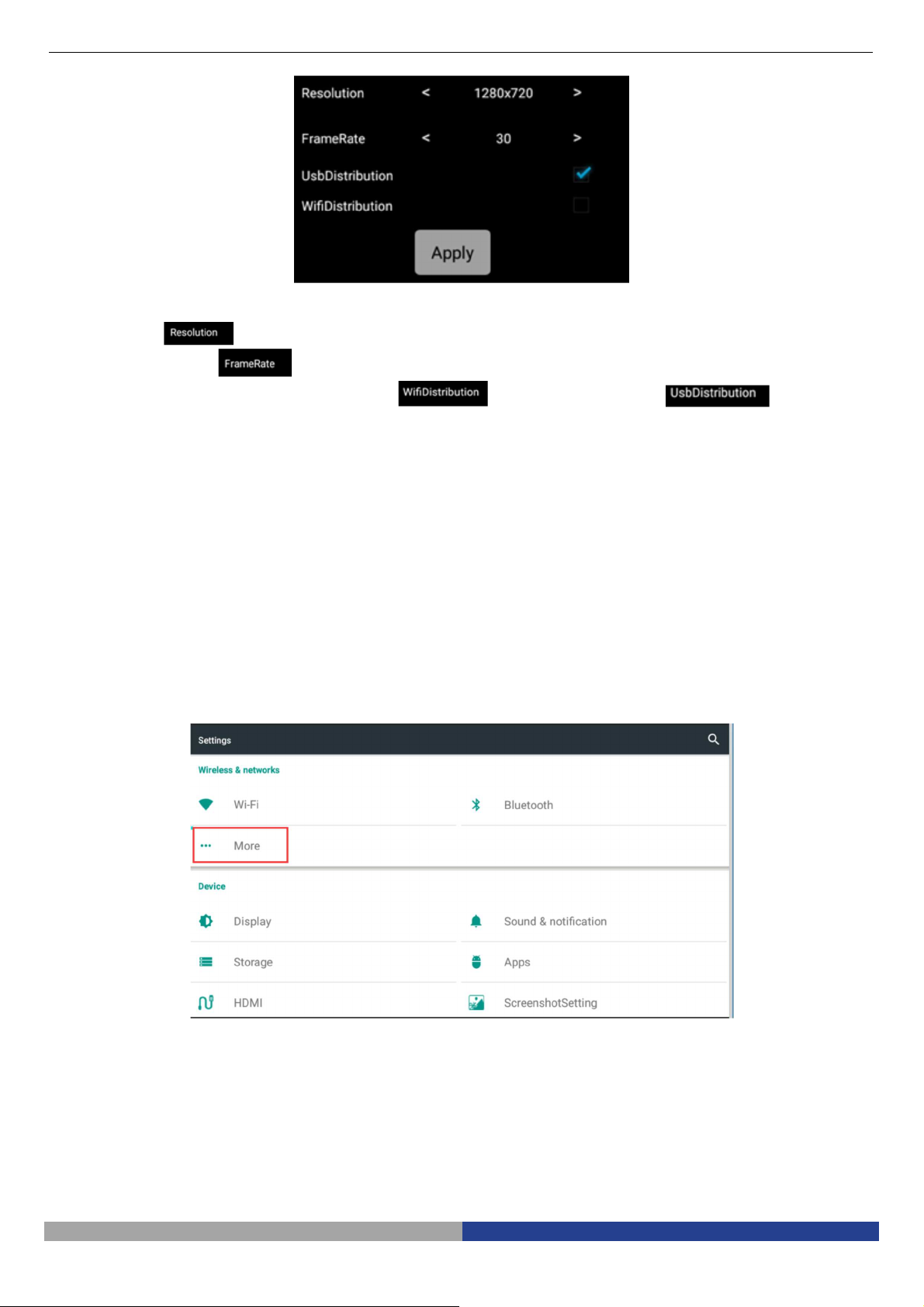
Setting module includes Resolution, Frame Rate and Transmission mode.
The Resolution has 4 options, respectively: 2688*1520, 1920*1080, 1280*720, 672*376.
The Frame Rate value can be selected among 0FPS / 15FPS / 30FPS.
The Transmission mode has two options: WiFi and USB transmission .
7.8 Image real-time transmission
7.8.1 WiFi transmission
The software can not only capture and display the images in local, but also can do real-time transmission by
external devices. WiFi hotspot transmission is not only one-to-one, also support multi-user to share. It only
requires the shared equipment and system are connected to the same network address. For it, we can through
spontaneous hotspot or through external WiFi hotspots.
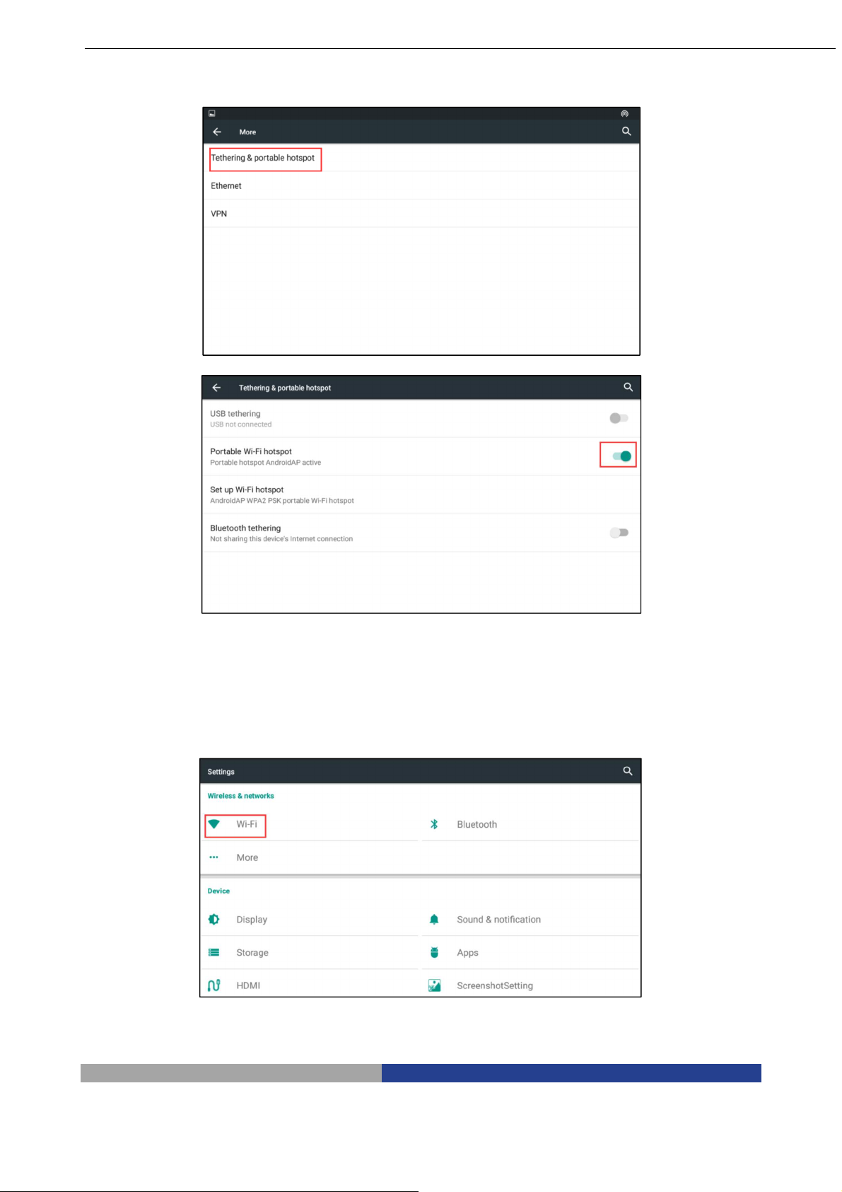
1. In case of spontaneous hotspot, you need to open the network share hotspot service in system
settings. For further details please refer to the Step 1:
Step 1: Spontaneous hotspot
Open the “More” option in settings
Pag. 28
Page 29

Open the portable WLAN hotspot option
2. In case of an external WiFi hotspots, you may need to open the system Settings of WLAN option, even
on the need to connect the WiFi. For further details please refer to the Step 2:
Step 2: External WiFi hotspot
Open the “WLAN” in settings
Pag. 29
Page 30

Choose the shared network after “WLAN”opened.
Now open or WiFi shortcut key on the left menu bar, click on
in Settings: a string of IP address will appear .
External devices through player software can directly enter the IP address in input field, then click play, the
devices can get synchronized images as Inspection System.
7.8.2 USB Transmission
Real-time image transmission can be obtained through the USB to data transfer: the first operation is connect
the external mini USB interface of the module to the USB interface of receiver device, then click on the USB
output option in the Settings,
Pag. 30
Page 31

or click on the shortcut button on the left menu bar, and then open the installed software in receiver
device, choose the official version of the video capture program AMCap software, now you can use real-time
image transmission function.
7.9 Image / Video Switch
7.9.1 Image function
Choose the image button in Image / Video selection box . Click on the Image icon . If the screen is
showing the pictures’ storage place, it means that the image acquisition is done. You can directly access to the
gallery application to view the pictures, and also can click the local browse button to view.
7.9.2 Video Function
Like the Image function, choose the Video button in Image / Video selection box .Click on the Video icon :
now the icon becomes red , and the screen will show . This is the information that the video
recording is active. Clicking once again the icon it will return to its original status and the screen will show
. This means that the video recording has been completed. You can go to the gallery or click local
browse to view.
Start Recording
Pag. 31
Page 32

Finish Recording
7.10 Zoom Picture
You can enlarge the picture when browsing. This function is done through the bar-type control
, by moving from left to right the blue dot.
While performing measurement, zoom function has to be set at its minimum: zooming the image will result in
errors during measurements.
Pag. 32
Page 33

Problem
Cause
Solution
8 Troubleshooting
As the performance of software cannot play fully due to unfamiliar operations, the table below can provide
some solutions.
1) Clicking on WiFi button has
no effect and does not
appear the IP address.
2) Camera program is not
responding or forced
termination
3) Image distortion when
opening AWB
Hotspot sharing not open Open the hotspot sharing in
WLAN is not open. Open the WLAN in settings (refer
Resolution ratio (1520p) does not
support WiFi transmission
Too frequent and irregular
operation cause system error
response
Wrong settings
settings (refer to step 1)
to step 2)
Change to the feasible
resolution in the program
Settings
Restart
Start the automatic white
balance in the correct area that
close to white colour.
Pag. 33
Page 34

MANUALE DI ISTRUZIONI
Model
lo
IS-01
Serie INSPECTION SYSTEMS
Versione: 1
Issued: 1.0.0
Pag. 34
Page 35

IS-01
Video Microscopio da Ispezione Compatto
ISTRUZIONI
Questo manuale di istruzioni si riferisce alla guida operativa, alla risoluzione dei problemi e alla manutenzione
del Video Microscopio da Ispezione Compatto IS-01. Si prega di studiare attentamente questo manuale prima
di utilizzare lo strumento e di tenerlo a disposizione vicino allo stesso. Il produttore si riserva i diritti sulle
modifiche mediante lo sviluppo della tecnologia.
Sulla base del funzionamento garantito, le specifiche tecniche possono essere soggette a modifiche senza
preavviso.
Pag. 35
Page 36

Sommario
Hardware
1. Preparazione 38
1.1 Operazioni 38
1.2 Manutenzione 38
1.3 Componenti 39
2. Assemblaggio 41
2.1 Schema di assemblaggio 41
2.2 Procedura di assemblaggio 42
3. Uso del microscopio 45
3.1 Regolazione della tensione di messa a fuoco 45
3.2 Impostazione dell’illuminazione 45
3.3 Posizionare il campione 46
3.4 Regolazione della messa a fuoco 46
3.5 Blocco dell’ingrandimento 46
3.6 Uso dei tasti e dei connettori 47
4. Risoluzione dei problemi 48
5. Dati Ottici 49
Software
6. Panoramica 50
6.1 Avvio e Arresto del Software 50
6.1.1 Avvio del Software 50
6.1.2 Arresto del Software 50
6.2 Comandi Principali 51
6.2.1 Spiegazione dei comandi 51
6.2.2 Spiegazione delle icone 51
7. Uso del Software 53
7.1 Cartella di archiviazione 53
7.2 Regolazione di Colore e Esposizione 53
7.2.1 Regolazione Esposizione 54
7.2.2 Regolazione Colore 54
7.3 Calibrazione 54
7.4 Strumento Disegno 60
7.5 AWB (Bilanciamento Automatico del Bianco) 61
7.6 Funzione WDR 62
7.7 Tasto Setting 63
7.8 Trasmissione immagini in tempo reale 63
7.8.1 Trasmissione WiFi 63
7.8.2 Trasmissione USB 65
7.9 Tasto Immagine / Video 66
7.9.1 Funzione Immagine 66
7.9.2 Funzione Video 66
7.10 Zoom Immagine 67
8 Risoluzione dei problemi 68
Pag. 36
Page 37

1 Preparazione
1.1 Operazioni
1) Non esporre il microscopio a luce solare diretta. Il microscopio deve essere posizionato in un luogo
asciutto e pulito. Evitare alte temperature e vibrazioni violente.
2) Il microscopio è uno strumento di precisione; utilizzarlo sempre con cura, evitare urti ed impatti bruschi ed
evitare scossoni durante il trasporto.
3) Per mantenere l’immagine nitida, non lasciare ditate o sporcizia sulla superficie delle lenti.
4) Non ruotare mai le manopole destra e sinistra di messa a fuoco in direzioni opposte per non danneggiare
il microscopio.
1.2 Manutenzione
1) Mantenere pulita la superficie di tutte le lenti. Pulire delicatamente le lenti con un panno morbido o soffiare
via la polvere. Rimuovere delicatamente tracce di unto o ditate dalla superficie delle lenti usando una
cartina umettata con una miscela di alcool ed etere (70%-30%).
2) Non usare solventi organici per pulire le superfici delle altre parti del microscopio (specialmente le parti in
plastica). Se necessario usare un detergente neutro.
3) Non tentare di smontare il microscopio, per non danneggiarlo o ridurne le sue funzioni.
4) Dopo l’uso, coprire sempre il microscopio con una copertina antipolvere e conservarlo in un luogo
asciutto.
Per mantenere la corretta funzionalità del microscopio, effettuare manutenzioni periodiche. Contattare il vostro
rivenditore di zona per maggiori informazioni.
Pag. 37
Page 38

luminosa del LED
1.3 Componenti
Monitor
Corpo del
microscopio
Porta HDMItor
Variatore di
ingrandimento
Illuminatore
circolare LED
Base del
microscopio
Porta MINI USB
Porta USB
Tasto Video
Tasto Camera
Accensione
Manopola di
messa a fuoco
Manopole
regolazione
Pag. 38
Page 39

Alimentatore
Fessura SD
card
Connettore
Blocco per
variatore di
ingrandimento
Pag. 39
Page 40

2. Assemblaggio
2-1 Schema di assemblaggio
Di seguito viene indicato lo schema di assemblaggio, per descrivere come montare i componenti; i numeri
indicano l’ordine di assemblaggio.
Prima del montaggio, assicurarsi che non ci sia polvere, sporcizia o altri materiali che possano
disturbare. Montare con cura e non rimuovere parti o toccare la superficie in vetro.
Conservare il cacciavite esagonale. Servirà in futuro per il montaggio di altre parti.
Pag. 40
Page 41

2-2-1 Montaggio dell’anello di prolunga (
Fig. 1
-
2-2-2 Assemblare il monitor
HDMI (fig.3
-
4)
2.2 Procedura di Assemblaggio
Fig. 1
Fig. 2
Fig. 3
Fig. 4
2)
1. Svitare le tre viti poste sotto la base del
microscopio per rimuovere il braccio del
microscopio.
2. Montare l’anello di prolunga sulla base, quindi
rimontare il braccio del microscopio.
•
L’anello di prolunga viene usato per aumentare
la lunghezza del braccio del microscopio,
aumentando così la distanza di lavoro.
1. Svitare le tre viti sulla parte superiore del
braccio del microscopio e quindi rimuovere il
tappo.
2.
Montare il tappo in dotazione avvitando le tre
viti rimosse in precedenza.
3. Montare il supporto rettangolare del monitor
HDMI usando le due viti in dotazione.
4. Montare il monitor HDMI sul supporto
rettangolare usando le viti in dotazione.
Pag. 41
Page 42

2-2-3 Montare il corpo del Microscopio
(Fig.
2-2-4
Montare l’illuminatore LED (Fig. 6)
2-2-5
Collegare il cavo elettrico (Fig. 7)
caratteristiche.
5)
1. Allineare la coda di rondine ① del corpo del
microscopio alla coda di rondine ② del
braccio del microscopio ed inserirlo dall’alto
(come mostrato in figura).
2. Serrare la vite M4 nel corpo del microscopio
③ con una brugola esagonale M4
(lunghezza 2 mm).
Fig. 5
1. Inserire l’illuminatore circolare LED sul corpo
del microscopio nella direzione indicate dalla
freccia, allineare I tre fori delle viti di fissaggio
① con gli intagli ②, e serrare le viti con una
brugola esagonale M4 (lunghezza 2 mm).
Fig. 6
1. Inserire il terminale dell’alimentatore esterno
① nel connettore posto sul microscopio ②,
e il microscopio può essere acceso.
Non esercitare una forza eccessiva
quando il cavo di alimentazione è
piegato o attorcigliato, altrimenti si
danneggia.
Usare il cavo in dotazione. Se venisse
perso o se si danneggia, scegliere un
alimentatore esterno con le medesime
Fig. 7
Pag. 42
Page 43

2-2-6 Montare le lenti addizionali (
Fig. 8
-9-
Fig. 8
E’ possibile usare una qualsiasi delle lenti
addizionali disponibili (0.5x o 1.4x). Per fare
ciò, seguire la procedura:
1. Rimuovere l’illuminatore circolare dalla
2.
10)
parte inferiore del microscopio. (Fig. 8)
Usando il cacciavite a brugola in
dotazione, allentare le viti poste
frontalmente e lateralmente per
rimuovere il supporto dell’illuminatore
circolare LED. (Fig. 9)
Fig. 9
Fig. 10
3. Svitare la lente attualmente installata e
sostituirla con la lente addizionale
desiderata. (Fig. 10)
4. Rimontare il tutto ripetendo alla rovescia
tutta la procedura compiuta iun
precedenza.
Pag. 43
Page 44

3-1 Regola
zione della
tensione
di messa a
3-2
Impostare l’illuminazione
(Fig. 12
-
13)
3. Uso del microscopio
Fig. 11
fuoco (Fig. 11)
1. Per regolare la tensione di messa a fuoco,
tenere ferma la manopola di sinistra e
ruotare la manopola destra ①. Per
aumentare la tensione ruotare in senso
orario, per diminuirla ruotare in senso
antiorario.
2.
Regolare la tensione in modo appropriato,
per evitare che il microscopio scenda da
solo per gravità durante l’osservazione ma
anche per consentire una messa a fuoco
confortevole
.
1. Inserire il cavo elettrico ② del corpo del
microscopio nel connettore
dell’illuminatore circolare ③, quindi
accendere l’interruttore ① per accendere
la sorgente luminosa.
Fig. 12
Fig. 13
2.
Ruotare le manopole di regolazione
dell’intensità luminosa per regolare la
luminosità.
Pag. 44
Page 45

3-3
Posizionare il campione
(Fig. 14)
3-4
Regolazione della messa a fuoco (Fig.
3-5
Blocco dell’ingrandimento
(Fig. 16)
Fig. 14
Fig. 15
1.
Posizionare il campione sulla base e
trovare il punto esatto per l’osservazione
sotto il microscopio.
15)
1. Ruotare l’anello del variatore di
ingrandimento ① al Massimo
ingrandimento.
2. Osservare l’immagine a monitor. Se non
fosse nitida ruotare la manopola di messa
a fuoco ② fino ad ottenere un’immagine
nitida.
3. Ruotare l’anello del variatore di
ingrandimento al minimo ingrandimento.
L’immagine è a fuoco.
La parafocalità tra massimo e minimo
ingrandimento è pre-regolata in
fabbrica.
Fig. 16
1) Se è necessario un certo ingrandimento o
si vuole evitare uno spostamento
accidentale della manopola del variatore di
ingrandimento, bloccare la vite di blocco ①
con una brugola esagonale M4 (lunghezza
3 mm).
Pag. 45
Page 46

3-6
Uso dei tasti e
dei connettori (Fig. 17
-
Fig. 17
Fig. 18
18)
1. Premere il tasto ON-OFF ① per 3-5
secondi, Il LED ⑦ passa da arancione a
verde, indicando che il microscopio si sta
avviando.
Quando il LED lampeggia, significa che
la telecamera è in funzione.
2. Tasto Camera ②: quando la telecamera è
in funzione premere una volta per acquisire
un’immagine.
3. Tasto Video ③: quando la telecamera è in
funzione premere una volta per avviare la
registrazione e premere nuovamente per
arrestarla.
4. Connettore cavo HDMI ④: collegare il
cavo HDMI per proiettare l’immagine ad
alta definizione.
5. Connettore cavo USB⑤: collegare il cavo
USB ad altri dispositivi quali mouse o
dischi USB.
6. Connettore cavo MINI⑥: collegare il cavo
MINI per esportare le immagini su USB.
7.
SD card: come mostrato in figura
posizionare l’intaglio verso sinistra ed
inserire la card. (Fig. 18)
Pag. 46
Page 47

Problem
a Caus
a Solu
zione
1.
2.
3.
4.
5.
6.
7.
8.
9.
10.
11.
4. Risoluzione dei problemi
Poiché le prestazioni del microscopio potrebbero non soddisfare completamente a causa di operazioni non
familiari, la tabella seguente può fornire alcune soluzioni.
Sporco o polvere visibili in
osservazione.
L’immagine a video non è nitida Sporcizia sulla superficie delle lenti Pulire le lenti
L’immagine non è visibile a
monitor
Sporcizia sul campione Pulire il campione
Sporcizia sulla superficie della
telecamera
Messa a fuoco non corretta Rimettere a fuoco
L’interruttore non è acceso Accendere l’interruttore principale del
Il cavo dell’alimentatore non è ben
collegato
Pulire la superficie della telecamera
microscopio
Verificare le connessioni
Immagine troppo chiara o troppo
scura.
Il monitor non risponde e
lampeggia
La manopola della messa a fuoco
è dura
L’immagine non è chiara a causa
della discesa per gravità del
microscopio
Il microscopio non può cambiare
ingrandimento
L’illuminatore a LED non si
accende quando è alimentato.
L’illuminatore a LED si brucia
velocemente
La luminosità non è sufficiente Voltaggio troppo basso Usare un alimentatore adeguato.
L’illuminatore circolare a LED ha una
regolazione sbagliata
Impostazioni sbagliate del monitor Aprire le impostazioni del monitor per
Troppe operazioni eseguite
contemporaneamente, che portano
ad un errore del sistema
La frizione è troppo serrata. Allentare la frizione
La frizione è troppo allentata. Serrare la frizione.
La vite di blocco è serrata Allentare la vite di blocco
Nessuna alimentazione. Verificare le connessioni
L’illuminatore è bruciatot Sostituire l’illuminatore
Voltaggio troppo elevato Usare un alimentatore adeguato.
Regolare la luminosità
dell’iluminatore
regolare la luminosità
Riavviare
Pag. 47
Page 48

5. Dati ottici
Obiettivo Ingrandimento ottico Ingrandimento a
Monitor
0.5x
1x
1.4x
Calcolo eseguito con un monitor HDMI 11,5”
0.35x 8.4x 26 16
0.5x 12x 18.2 11.2
0.75x 18x 12.12 7.4
1x 24x 9.1 5.6
1.5x 36x 6.06 3.72
2x 48x 4.54 2.8
2.5x 60x 3.64 2.24
0.7x 16.8x 13 8
1x 24x 9.1 5.6
1.5x 36x 6.06 3.7
2x 48x 4.55 2.8
3x 72x 3.03 1.86
4x 96x 2.27 1.4
5x 120x 1.82 1.12
0.98x 23.52x 9.28 5.71
1.4x 33.6x 6.5 4
2.1x 50.4x 4.33 2.64
2.8x 67.2x 3.25 2
4.2x 100.8x 2.16 1.32
5.6x 134.4x 1.62 1
7x 168x 1.3 0.8
Campo Visivo
Orizzontale (mm)
Campo Visivo
Verticale (mm)
W.D.
(mm)
170
135
100
Pag. 48
Page 49

6. Panoramica
6.1 Avvio e Arresto del Software
6.1.1 Avvio del Software
Cliccare sull’icona per avviare il software.
6.1.2 Arresto del Software
Cliccare sul tasto centrale. Tutte le applicazioni aperte in Android vengono visualizzate.
Per chiudere un’applicazione, cliccare sul tasto “X” in alto a destra di ogni finestra. Oppure scorrere a destra o a sinistra
la finestra dell’applicazione per terminarla.
Page 50
6.2 Comandi principali
6.2.1 Spiegazione dei comandi
Avviare il programma. Una volta avviato (l’inizializzazione richiede qualche secondo) il programma
mostra la seguente videata:
6.2.2 Spiegazione delle icone
Breve spiegazione delle icone:
: Cartella locale di salvataggio
: Regolazione colore ed esposizione
: Strumento disegno
: Blocco bilanciamento del bianco
: WDR
Pag. 50
Page 51

: Tasto WiFi
: Tasto USB
: Impostazioni
: Tasto Immagine / Video
: Zoom immagine
Pag. 51
Page 52

7 Uso del Software
7.1 Cartella di archiviazione
Cliccare sul tasto nella parte sinistra della barra del menu, per aprire la cartella di
archiviazione locale delle immagini o dei video acquisiti. Cliccare sulla cartella relativa per
visualizzare e modificare le immagini o i file video: (elimina immagini, elaborazioni, ecc)
7.2 Regolazione di Colore e Esposizione
Cliccare sul tasto nella parte sinistra della barra del menu, per aprire una finestra
semitrasparente sulla videata principale, che comprende la regolazione del colore e
dell’esposizione:
Regolazione Esposizione Regolazione Colore
Pag. 52
Page 53

7.2.1 Regolazione Esposizione
La finestra di regolazione dell’esposizione consente di selezionare il modo di esposizione, Manuale
o Automatico (AutoExposureLock “OFF” or “ON”) , la Compensazione
dell’Esposizione ,il Guadagno ,ed il
Tempo di Integrazione .
7.2.2 Regolazione Colore
La finestra di regolazione del colore consente di modificare la visualizzazione dell’immagine
proveniente dal microscopio.
E’ possibile regolare Luminosità , Contrasto ,
Saturazione , Crominanza .
7.3 Calibrazione
Per effettuare misurazioni precise è necessario calibrare il sistema.
Cliccare sul tasto righello . Appare una finestra:
Cliccare sul tasto “Edit”:
Appare una nuova finestra:
Pag. 53
Page 54

Cliccare sul tasto “Edit”
Appare una nuova finestra.
Cliccare su “Edit” e appare una nuova videata:
Posizionare un righello o un micrometro oggetto sotto il microscopio e mettere a fuoco.
Pag. 54
Page 55

Cliccare su “Add”:
Appare una nuova finestra.
Spostare il marcatore rosso sul righello
Pag. 55
Page 56

e cliccare su “Name”
Appare una finestra di input dove l’operatore deve inserire il nome dell’ingrandimento corrente:
Pag. 56
Page 57

Inserire il nome dell’ingrandimento (es. 0,7x) e cliccare su “Next”.
Appare un’altra finestra di input dove si deve inserire la lunghezza del marcatore appena
posizionato sul righello (es. 12 mm)
Cliccare su “DONE”.
Si viene riportati alla finestra di dialogo precedente.
Selezionare l’unità di misura (µm o mm).
Pag. 57
Page 58
Alla fine di tutte queste operazioni cliccare su “Calculate”. Appare questa finestra di dialogo:
Premere “OK” ed il primo punto di calibrazione viene salvato.
Ripetere tutti i passaggi per tutti gli ingrandimenti del microscopio.
Quando tutti gli ingrandimenti saranno calibrati si otterrà un elenco tipo questo:
Pag. 58
Page 59

Prima di eseguire una misura, è importante attivare la calibrazione relative all’ingrandimento in uso
con il microscopio.
7.4 Strumento Disegno
Sull’immagine visualizzata, l’operatore può avere molte funzioni utili.
Queste possono essere attivate cliccando il tasto righello .
Cliccando su questo tasto nella parte sinistra della barra del menu è possibile utilizzare una serie
di funzioni.
I comandi sono i seguenti: punto , linea retta , rettangolo , cerchio , cerchi
concentrici , distanza tra centri , crocefilo , linea perpendicolare , angolo , testo
, elimina un singolo oggetto (elimina l’ultimo oggetto tracciato o elimina dopo selezione)
,elimina tutto .
Cliccando il tasto colore linea , o il tasto colore carattere ,appare una nuova finestra di
scelta in cui appare una palette colore con 6 colori di scelta (giallo, nero, bianco, verde, rosso e
blu)
Pag. 59
Page 60

.
Selezionando uno di questi colori si modifica il colore di visualizzazione dell’oggetto selezionato.
Quando si usa su una immagine, l’utente può salvare l’immagine unitamente a tutte le linee
tracciate nella cartella di salvataggio locale (il video con le line tracciate non può essere salvato.
Il risultato della tracciatura delle linee può essere simile a questo:
Quando il sistema è debitamente calibrato, l’operatore può selezionare l’unità di misura da
visualizzare insieme alle misure tracciate (micron, millimetri ecc)
7.5 AWB (Bilanciamento Automatico del Bianco)
Cliccare sul tasto nella parte sinistra della barra del menu per avviare la funzione AWB
(Automatic White Balance).
Quando un’immagine viene acquisita sotto una luce fluorescente appare con una tinta verdastra;
sotto una luce alogena sarà tendente al giallo, mentre con la luce solare sarà tendente al blu: la
ragione di questo sta nel "bilanciamento del bianco".
Il ruolo del bilanciamento del bianco è quello di riconvertire il normale colore dell’immagine
nonostante I utilizzino queste diverse sorgenti luminose.
AWB è basato su un algoritmo dell’immagine, perciò quando si avvia il bilanciamento automatico
del bianco a microscopio, si deve selezionare un’area bianca per stabilire il “bianco”.
Porre un foglio di carta bianca sotto il microscopio: il sistema calcola in automatico la temperatura
colore e converte il colore dell’immagine visualizzata per ottenere il bianco.
Pag. 60
Page 61
7.6 Funzione WDR
WDR, acronimo per Wide Dynamic Range, comporta che le parti scure e le parti chiare
dell’immagine possono essere visualizzate chiaramente nello stesso momento. Quando la
funzione WDR è attiva, il sistema migliora la luminosità delle aree scure, specialmente usando uno
stereomicroscopio. Cliccare sul tasto nella parte sinistra della barra del menu, il tasto si
modifica in , e appare un messaggio nel centro dello schermo che avvisa dell’attivazione della
funzione WDR .
Funzione WDR attiva
Pag. 61
Page 62
Funzione WDR non attiva
7.7 Tasto Setting
Per aprire le funzioni di settaggio, cliccare sul tasto : appare una finestra semitrasparente.
Il modulo Setting comprende Resolution, Frame Rate e le modalità di Trasmissione.
La Resolution ha 4 opzioni: 2688*1520, 1920*1080, 1280*720, 672*376.
Il valore di Frame Rate può essere selezionato tra 0FPS / 15FPS / 30FPS.
La modalità di Trasmissione ha due opzioni: WiFi e USB .
7.8 Trasmissione immagini in tempo reale
7.8.1 Trasmissione WiFi
Il software oltre a visualizzare ed acquisire immagini, può anche effettuare una trasmissione di
immagini in tempo reale grazie a dispositive esterni. La trasmissione WiFi con hotspot può essere
“one-to-one” ma anche multi-utente. Richiede solo una condivisione del sistema e che i sistemi
siano collegati allo stesso indirizzo IP. Per questo si può utilizzare un hotspot spontaneo oppure
hotspots WiFi esterni.
1. In caso di hotspot spontaneo, si deve aprire il servizio di condivisione di hotspot della rete
nelle impostazioni di sistema. Vedere lo Step 1:
Step 1: Hotspot spontaneo
Pag. 62
Page 63
Aprire l’opzione “More” in Settings
Aprire l’opzione Portable WiFi hotspot
2. In caso di un hotspot WiFi esterno, si deve aprire l’opzione WLAN nelle impostazioni di
sistema, anche in caso di connettere il WiFi. Vedere lo Step 2:
Step 2: Hotspot WiFi esterno
Aprire “WiFi” in settings
Pag. 63
Page 64

Selezionare la rete condivisa dopo avere attivato il WiFi.
Ora aprire o cliccare sul tasto WiFi nella parte
sinistra della barra del menu, cliccare su in Settings: una tringa con l’indirizzo IP appare
.
Dispositivi esterni con software dedicati possono accedere direttamente all’indirizzo IP nel campo
input, quindi cliccare si “play”: i dispositivi verranno sincronizzati al Software Inspection System.
7.8.2 Trasmissione USB
La trasmissione immagini in tempo reale può essere ottenuta tramite il trasferimento dati USB: la
prima operazione è quella di collegare il connettore MINI USB al connettore USB del dispositivo
ricevente, quindi cliccare il tasto dell’opzione uscita USB in Settings,
Pag. 64
Page 65

o cliccare il tasto nella parte sinistra della barra del menu, ed aprire il software nel dispositivo
ricevente. Selezionare la versione ufficiale del programma di cattura video AMCap software; ora la
trasmissione di immagini in tempo reale è possibile.
7.9 Tasto Immagine / Video
7.9.1 Funzione Immagine
Selezionare il tasto Immagine nel campo di selezione Immagine / Video . Cliccare sull’icona
Immagine . Se lo schermo mostra la cartella di destinazione delle immagini, significa che
l’acquisizione è stata eseguita. Si può accedere direttamente alla galleria immagini per visualizzare
le immagini o cliccare il tasto .
7.9.2 Funzione Video
Esattamente come per la funzione Immagine, selezionare il tasto Video nel campo di selezione
Immagine / Video. Cliccare sull’icona Video : l’icona diventa rossa , e lo schermo mostra
. Questo indica che l’acquisizione di un video è in corso. Cliccare nuovamente l’icona la
riporterà nuovamente alla sua condizione originale e lo schermo mostra . Ciò
significa che l’acquisizione di un video è terminata. Si può accedere direttamente alla galleria
immagini per visualizzare il video o cliccare il tasto .
Avvio registrazione
Pag. 65
Page 66

Arresto registrazione
7.10 Zoom Immagine
Durante il lavoro è possibile effettuare uno zoom sull’immagine proiettata a monitor. Questa
funzione è possibile utilizzando il cursore , spostandolo da sinistra a destra.
Durante l’esecuzione di misurazioni, lo zoom deve essere tenuto al minimo: lo zoom dell’immagine
potrebbe portare ad errori di misurazione.
Pag. 66
Page 67

Problem
a Caus
a S
oluzione
1.
2.
3.
8 Risoluzione dei problemi
Poiché le prestazioni del software potrebbero non soddisfare completamente a causa di operazioni
non familiari, la tabella seguente può fornire alcune soluzioni.
.
Cliccando sul tasto WiFi non
succede nulla e non appare
l’indirizzo IP.
Il Sistema non risponde Troppe operazioni eseguite
Disrtorsione imagine quando
si attiva AWB
Condivisione di hotspot non attiva Attivare la condivisione di
hotspot in settings (vedere step
1)
WiFi non attivo. Attivare il WiFi in settings
(vedere step 2)
La risoluzione (1520p) non
supporta la trasmissione WiFi
contemporaneamente, che
portano ad un errore del sistema
Impostazione errata
Passare ad una risoluzione che
consente la trasmissione in
Settings
Riavviare
Avviare il bilanciamento del
bianco in un’area corretta che
consenta l’esecuzione della
funzioone.
Pag. 67
Page 68

'LVWULEXWHGE\
100 Lauman Lane, Suite A, Hicksville, NY 11801
Tel: (877) 877-7274 | Fax: (516) 801-2046
Email: Info@nyscopes.com
www.microscopeinternational.com
OPTIKA S.r.l.
Via Rigla, 30 - 24010 Ponteranica (BG) - ITALIA Tel.: +39 035.571.392 - Fax: +39 035.571.435
mailto:minfo@optikamicroscopes.com - www.optikamicroscopes.com
 Loading...