

Page 1

Version: 1
Issued: 30, 05, 2016
Model
IM-2
IM-2ERGO
IM Series
INSTRUCTION MANUAL
Page 2

Page 2
Table of Contents
Warning
Symbols and conventions
Safety Information
Intended use
List of accessories and spare parts
Overview
Unpacking
Assembling
Using the microscope
Maintenance
Troubleshooting
Equipment disposal
Page 3
Page 3
Warning
This microscope is a scientic precision instrument designed to last for many years with a minimum of maintenance. It is built to high optical and mechanical standards and to withstand daily use. We remind you that this
manual contains important information on safety and maintenance, and that it must therefore be made accessible to the instrument users. We decline any responsibility deriving from incorrect instrument use uses that does
not comply with this manual.
Symbols and conventions
The following chart is an illustrated glossary of the symbols that are used in this manual.
CAUTION
This symbol indicates a potential risk and alerts you to proceed with caution.
ELECTRICAL SHOCK
This symbol indicates a risk of electrical shock.
Safety Information
Avoiding Electrical Shock
Before plugging in the power supply, make sure that the supplying voltage of your region matches with the
operation voltage of the equipment and that the lamp switch is in off position. Users should observe all safety
regulations of the region. The equipment has acquired the CE safety label. However, users have full responsibility to use this equipment safely. Please follow the guidelines below, and read this manual in its entirety to ensure
safe operation of the unit.
Intended use
For research and teaching use only. Not intended for any animal or human therapeutic or diagnostic use.
Page 4
Page 4
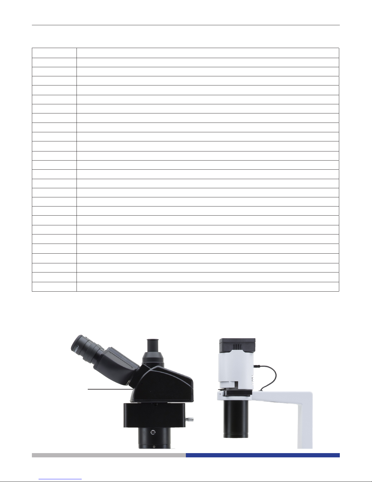
List of accessories and spare parts
CAT. NO. DESCRIPTION
M-755 Ergonomical binocular head.
M-755.1 Trinocular attachment for Ergonomical binocular head (M-755).
M-017 Eyepiece EWF10x/22mm.
M-021 Eyepiece micrometer EWF10x/22mm.
M-005 26x76 mm micrometric slide. Range 1 mm, div. 0,01 mm.
M-770 Objective IOS LWD PLAN Achromatic 4x/0,10 (w.d. 18mm).
M-771 Objective IOS LWD PLAN Achromatic for phase contrast 10x/0,25 (w.d. 10mm).
M-772 Objective IOS LWD PLAN Achromatic for phase contrast 20x/0,40 (w.d. 5,1mm).
M-773 Objective IOS LWD PLAN Achromatic 40x/0,60 (w.d. 2,6mm).
M-774 Objective IOS LWD PLAN Achromatic for phase contrast 40x/0,60 (to use with M-776).
M-776 Phase ring 40x (to use with M-774).
M-778 C-mount adapter for 1/3”,1/2” and 2/3” sensor.
M-036 Dust cover type 7.
M-795 Fluorescence attachment, HBO100W, B and G filtersets (only for IM-2).
M-792.1 Mechanical stage for IM-2 series.
M-793.1 Holder for Petri diameter 38mm (M-793.2 needed).
M-793.2 Holder for Terasaki and Petri diameter 65mm.
M-793.3 Holder for slide and Petri diameter 54mm.
M-793.4 Holder for 2+2 slides.
M-793.6 Holder for Utermöhl-Chamber (M-793.3 needed).
M-793.8 Load-bearing side extension for IM-2 series.
M-173 Photo adapter for APS-C and Full Frame Reflex cameras.
M-114 C-Mount adapter for 1/2” sensor.
M-116 C-Mount adapter for 2/3” sensor.
VP-IM IQ/OQ/PQ Validation Protocols.
Overview
M-755 + M-755.1
ERGONOMICAL
TRINOCULAR
HEAD
Page 5
Page 5
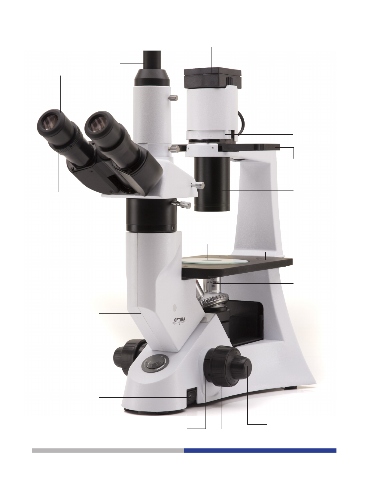
Overview
FILTER HOLDER
PHASE
CONTRAST SLIDER
TRINOCULAR
VIEWING
TUBE
(FIXED)
DIOPTRIC
ADJUSTMENT
RING
EYEPIECE
LED
HOUSING
CONDENSER
COARSE
FOCUS KNOB
FINE FOCUS KNOB
TENSION
ADJUSTMENT
COLLAR
OBJECTIVE
STAGE
MICROSCOPE
BODY
LIGHT
ADJUSTEMENT
MAIN SWITCH
GLASS STAGE
INSERT
Page 6
Page 6
Unpacking
The microscope is housed in a moulded Styrofoam container. Remove the tape from the edge of the container
and lift the top half of the container. Take some care to avoid that the optical items (objectives and eyepieces)
fall out and get damaged. Using both hands (one around the arm and one around the base), lift the microscope
from the container and put it on a stable desk.
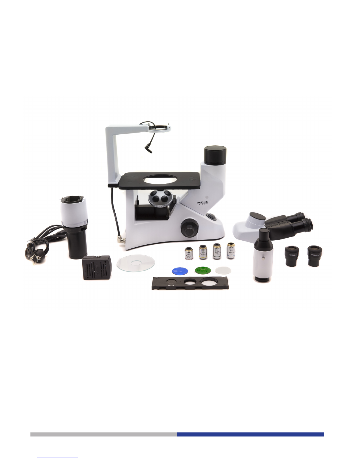
Assembling
Once you open the box, these are the microscope’s components:
① Microscope body
② Condenser
③ Head
④ LED illuminator
⑤ Phase contrast slide
⑥ Eyepieces
⑦ Trinocular tube
⑧ Glass insert for stage
⑨ Objectives
⑩ Power cable
⑪ Brighteld lters (Blue, green and frosted)
⑪
⑩
③
④
⑤
⑥
⑦
⑧
⑨
①
②
Page 7

Page 7
③
Fig.4
Fig.5
Fig.3
Fig.1
Fig.2
1. Turning the coarse focusing knob ① till the
nosepiece reaches its lowest position.
► For a safe transport, the nosepiece is
placed in the lowest position and the
tension adjustment collar ② is adjust-
ed to the appropriate tension when the
microscope leaves the factory. (Fig.3)
2. Screw the lowest magnication objective
on to the turret from the right side, then
turn the turret clockwise. Mount the other
objectives in the same way, following the
sequence from low to high.
► Note: the objectives can also be in-
stalled through the stage opening.
(Fig.4)
► Clean the objectives regularly. In inverted
microscopes, the objectives are very sensitive to dust.
► To prevent dust and contamination from
entering the microscope, cover all the unused holes with dust caps ③. (Fig.5)
► When operating, use the low magnication
objective (10X) to search and focus the
specimen, then switch to higher magnica-
tions.
► When switching between objectives, slowly
turn the nosepiece until it clicks. The click
means that the objective is in the right position, in the center of the light path.
1. Take out the dust cap and x the optical
head using the screw ①. (Fig.1)
2. Insert the trinocular tube into the exit above
the head, and x it using the screw ②.
(Fig.2)
①
①
②
②
Installing the objectives
Installing the optical head
Page 8

Page 8
1. When using the glass stage, make sure
that the insert is horizontal.
2. Install the stage insert in the stage opening. (Fig.8)
Installing the stage insert
Installing the eyepieces
Insert both eyepieces into the tubes of the
optical head. (Fig.9)
Fig.8
Fig.9
Fig.6
Fig.7
The stage extension can be installed on either
side of the stage to enlarge the working surface. The mechanical stage must be installed
on the side opposite the extension.
For right-handed operators, the mechanical
stage is normally installed on the right side.
1. Installing the stage extension: Screw the
bolts on to the extension, then mount the
extension from below the stage. (Fig.6)
2. Installing the mechanical stage: As for the
extension, the mechanical stage is xed
with two bolts under the stage. (Fig.7)
Installing the stage extension and
the mechanical stage (OPTIONAL)
Page 9

Page 9
► Remove the lter holder, then install the
color lters you need. (Fig.13, Fig.14)
Mount the color lter at as shown in ①,
verifying that they are not tilted.
► If the color lter is tilted or otherwise
out of place ②, it may fall.
The color lters can be stacked in the
holder. This allows to install as many lters
as needed, as long as the whole thickness
is less than 11 mm.
Installing the color lters
Fig.13
Fig.14
Fig.10
Fig.11
Fig.12
1. Insert the condenser illumination unit into
the bracket. (Fig.10)
2. Turn the condenser illumination unit
clockwise about 90°, with the “AS” mark of
lter holder facing forwards. Screw the 2
xing mut with the supplied allen wrench.
(Fig.11)
3. Insert the connector plug ② into the con-
nector jack.
4. Push the LED housing gently into the holes of the illumination unit. (Fig.12)
Installing the condenser
illumination unit and the LED
housing
①
②
Page 10

Page 10
1. Turn the main switch ① to “O”(off) before
connecting the power cord. (Fig.15)
2. Insert the cable into the power socket of
the microscope. (Fig.16)
3. Plug the power cord into the mains socket. Check for a safe connection.
► Please use the supplied power cord.
If lost or damaged, please refer to
qualied service.
► Connect the power cord to a grounded
(earthed) power supply only.
Before replacing the fuse, turn the main switch
to “O” (off) and unplug the power cord.
Rotate the fuse support out of the holder using
a straight screwdriver. Insert a new fuse in the
support, then rotate the support back into the
holder. (Fig.17)
► Fuse rating:
see back of the microscope.
Connecting the power cord
Replacing the fuse
Fig.15
Fig.16
Fig.17
①
Page 11

Page 11
Setting the specimen
► For the best image quality, use asks,
Petri dishes and slides with a 1.2 mm
thickness.
1. Place the proper insert for your specimen
(according to the table on the right) on the
stage, and x it with the stage clip.
2. Turning the X and Y knobs, move the
specimen to the required position. (Movement Range: 120 (width) × 78 (length)
mm).
Moving the specimen
Move the specimen to the desired position by
freehand or by turning the knobs of the mechanical stage.
► When switching objectives, take care
not to touch the adaptor plates with
the objectives, as their weight may
damage the front lens.
M-793.1
Holder for Petri diameter 38mm (M-793.2 needed)
M-793.2
Holder for Terasaki and Petri diameter 65mm.
M-793.3
Holder for slide and Petri diameter 54mm.
M-793.4
Holder for 2+2 slides.
M-793.6
Holder for Utermöhl-Chamber (M-793.3 needed).
M-793.8
Load-bearing side extension for IM-2 series
M-792.1
Mechanical stage for IM-2 series.
INITIAL SETUP
STAGE (OPTIONAL)
Using the microscope
①
②
Fig.18
Turning on the LED
Connect the power, turn on the main switch ①.
Adjusting the brightness
Turn the brightness adjustment knob ② to in-
crease and decrease the brightness. (Fig.18)
Adjusting the tension
► The coarse focusing knob ③ is pre
adjusted to a tight tension upon leaving the factory.
If the nosepiece drops down by itself, or the
specimen defocuses while adjusting the ne
focus knob ④, the coarse focus knob is too
loose. Turning the tension adjustment collar
⑤ in clockwise direction tightens the coarse
focus tension ③. Rotate in the opposite direc-
tion to decrease the tension. (Fig.18)
③
④
⑤
Page 12

Page 12
Dioptric adjustment
1. Look into the right eyepiece with your right
eye only, and focus on the specimen.
2. Look into the left eyepiece with your left
eye only. If the image is not sharp, use
the dioptric adjustment ring ① to compen-
sate. (Fig.19)
► The adjustment range is ±5 diopter.
The number indicated on the adjustment ring graduation should correspond to the operator’s dioptric correction.
Adjusting the interpupillary distance
Observing with both eyes, hold the two eyepiece prism assemblies. Rotate them around
their common axis until the elds of view co-
incide.
► The graduation on the interpupillary
distance indicator ②, pointed by the
spot “.” on the eyepiece holder, shows
the distance between the operator’s
eyes. (Fig.20)
The range of the interpupillary distance is 48-
75mm.
Selecting the light path
Pull the light path selector lever ③ sideways
using your thumb, selecting the light path you
need. (Fig.21)
VIEWING TUBE
②
Fig.19
Fig.20
Fig.21
LIGHT PATH SELECTOR
LEVER
BRIGHTNESS APPLICATION
In 100% used for binocular
observation
Binocular
observation
Out 20% used for binocular observation, and
80% used for video or photography
Binocular observation, television, and
micrography or video can be operated
simultaneously
③
①
Page 13

Page 13
Using color lters
Selecting the appropriate color lters according your need. (Fig.22)
You can stack a group of color lters in the lter holder, if you ensure that they are level and
that the whole thickness is less than 11mm.
Using the aperture diaphragm
When in brighteld observation, the aperture
diaphragm controls the numerical aperture of
the illumination system. When the numerical
aperture of the objective and the aperture of
the illumination system match, the highest resolution is achieved.
The aperture can be changed by moving the
aperture adjustment lever. ① is the image of
the aperture diaphragm, ② is the edge of the
objective).
Generally, when observing a fully chromatic
specimen, you need to set the size of the condenser to 70-80% of the aperture of the objective. When observing unstained samples (e.g.
bacteria), start from 70% and slowly turn the
aperture diaphragm lever clockwise. (Fig.23)
ILLUMINATION UNIT
Phase contrast slider
Adjustable phase slider.
● The light ring is pre-centered when the
microscope leaves the factory. It should
therefore need no further adjustment. If
a recentering is needed, it can be per-
formed via the two side bolts.
● The 10X/20X light ring ① must be used
with 10X and 20X phase contrast objectives, the opening ② can be used with the
40X phase ring (optional), and the opening ③ is used for bright eld. (Fig.24)
Installing the phase contrast slider
1. Insert the slider into the illumination sys-
tem, printed face up.
2. Pull the slider into the desired position, to
the click stop.
3. When in phase contrast observation, keep
the aperture diaphragm adjustment lever
on the “O” (open) position. (Fig.25)
PHASE CONTRAST
Fig.22
Fig.24
Fig.25
Fig.23
70-
30-
70-80%
30-20%
COLOR
FILTER
USE
Green Single contrast color lter used for phase
contrast microscopy
Blue Color temperature compensation color lter
blue used for bright eld observation and
microphotography
Frosted Used to increase the uniformity of illumination.
①
①
②
②
③
Page 14

Page 14
Installing the photography adapter
1. To activate the video port, pull out light
path selector lever. (Fig.26)
2. Install the photography adapter into the
trinocular port according to its instructions.
(Fig.27)
3. Attach the camera ring (if any) to the
adapter.
4. Attach the camera to the ring.
● Warning: for some cameras (mainly reex) the ring is not included with the microscope, and it should be supplied by the
user.
● For the photography of dark specimens,
obscure the eyepieces and the viewnder
with a dark cloth in order to reduce stray
light.
► When shooting with a SLR, the mirror
movement may cause camera movement. Please lift the mirror, use long
exposure times and use an extension
cord.
MICROPHOTOGRAPHY
Fig.26
Fig.27
Camera
Adapter
Page 15

Page 15
Maintenance
Microscopy environment
This microscope is recommended to be used in a clean, dry and shock free environment with a temperature of
5°-40°C and a maximum relative humidity of 75 % (non condensing). Use a dehumidier if needed.
To think about when and after using the microscope
• The microscope should always be kept vertically when moving it and be careful so that no
moving parts, such as the eyepieces, fall out.
• Never mishandle or impose unnecessary force on the microscope.
• Never attempt to service the microscope yourself.
• After use, turn off the light immediately, cover the microscope with the included
dust-cover, and keep it in a dry and clean place.
Electrical safety precautions
• Before plugging in the power supply, make sure that the supplying voltage of your region
matches with the operation voltage of the equipment and that the lamp switch is in off-
position.
•
Users should observe all safety regulations of the region. The equipment has acquired
the CE safety label. However, users do have full responsibility to use this equipment safely.
Cleaning the optics
• If the optical parts need to be cleaned try rst to: use compressed air.
• If that is not sufcient: use a soft lint-free piece of cloth with water and a mild detergent.
• And as a nal option: use the piece of cloth moistened with a 3:7 mixture of ethanol and ether.
Note: ethanol and ether are highly ammable liquids. Do not use them near a heat source, near sparks or
near electric equipment. Use these chemicals in a well ventilated room.
• Remember to never wipe the surface of any optical items with your hands. Fingerprints can damage the
optics.
• Do not disassemble objectives or eyepieces in attempt to clean them.
For the best results, use the OPTIKA cleaning kit (see catalogue).
If you need to send the microscope to Optika for maintenance, please use the original packaging.
Page 16

Page 16
Troubleshooting
Review the information in the table below to troubleshoot operating problems.
PROBLEM CAUSE SOLUTION
I. Optical Section:
The illumination is open, but the eld
of view is dark.
The plug of the LED holder is
not connected to the illumina-
tion set
Connect them
The brightness is too low Adjust to a proper setting
Too many colour lters have
been stacked
Minimize the number of the lters
The edge of the eld of view is
vignetted or the brightness is asym-
metric.
The nosepiece is not in the correct position
Turn the nosepiece to a click stop
The color lter is partially
inserted
Insert the lter to full depth
The phase contrast slider is not
in the proper position
Move the slider to a click stop
Dust and stains can be seen in the
eld of view.
There are stains and dust on
the specimen
Clean the specimen
There are stains and dust on
the eyepiece
Clean the eyepiece
There is an apparent double image. The size of the aperture dia-
phragm is too small
Open the aperture diaphragm
Poor image quality:
The image is not sharp
The contrast is not high
The details are not clear
The phase contrast is low.
The nosepiece is not in the
center of the light path
Turn the nosepiece to a click stop
The aperture diaphragm in
the view of eld is opened too
much or too little
Adjust the aperture diaphragm
The lenses (condenser, objective, eyepieces are culture
dish) is dirty
Thoroughly clean all the optical system
In phase contrast observation,
the bottom thickness of the
sample is more than 1.2mm
Use a sample holder whose bottom thickness is less than 1.2mm
A bright eld objective is used
for phase contrast observation
Switch to a phase contrast objective
The condenser ring is not
aligned with the objective
phase ring
Adjust the condenser ring to match the
objective phase ring
The light ring and/or the phase
contrast ring is not centered
Adjust the bolts to center them
The objective used is not compatible with the phase ring
Please use a compatible objective
The phase contrast depends on
the sample position
The sample holder is not at. Move the
sample around until a compatible area is
found.
Page 17

Page 17
One side of the image is out of focus. The nosepiece is not in the
center of the light path
Turn the nosepiece to a click stop
The specimen is out of place
(tilted)
Place the specimen at on the stage.
The optical performance of the
sample cover glass is poor
Use a cover glass of better quality
II. Mechanical Section:
The coarse focus knob is hard to
turn.
The tension adjustment collar is
too tight
Loosen the tension adjustment collar
The focus is unstable. The tension adjustment collar is
too loose
Tighten the tension adjustment collar
III. Electric section
The LED doesn’t turn on. No power supply Check the power cord connection
The brightness is not enough The brightness adjustment is
low
Adjust the brightness
The light blinks The power cord is poorly con-
nected
Check the power cord
IV. Viewing tube assembly
The eld of view of the two eyes is
different
The interpupillar distance is not
correct
Adjust the interpupillar distance
The dioptric correction is not
right
Adjust the dioptric correction
The viewing technique is not
correct, and the operator is
straining the eyesight
When look into the objective, do not stare
at the specimen but look at the whole eld
of view. Periodically, move the eyes away
to look at a distant object, then back into
the objective
V. Microphotography and video
The image is unfocused Incorrect focussing Adjusting the focus system as in the pres-
ent manual
The edge of the image is unfocussed To some degree, it is inherent
to the nature of achromatic
objectives
The problem can be minimized by a correct
setting of the aperture diaphragm
Bright patches appear on the image Stray light is entering the
microscope through the eye-
pieces and through the camera
viewnder
Cover the eyepieces and the viewnder
with a dark cloth
Page 18

Page 18
Equipment disposal
Art.13 Dlsg 25 july 2005 N°151. “According to directives 2002/95/EC, 2002/96/EC and 2003/108/EC relating
to the reduction in the use of hazardous substances in electrical and electronic equipment and waste disposal.”
The basket symbol on equipment or on its box indicates that the product at the end of its useful life should be
collected separately from other waste.
The separate collection of this equipment at the end of its lifetime is organized and managed by the producer.
The user will have to contact the manufacturer and follow the rules that he adopted for end-of-life equipment
collection.
The collection of the equipment for recycling, treatment and environmentally compatible disposal, helps to prevent
possible adverse effects on the environment and health and promotes reuse and/or recycling of materials of the
equipment.
Improper disposal of the product involves the application of administrative penalties as provided by the laws in force.
Page 19

Page 20

OPTIKA S.r.l.
Via Rigla, 30 - 24010 Ponteranica (BG) - ITALIA Tel.: +39 035.571.392 - Fax: +39 035.571.435
info@optikamicroscopes.com - www.optikamicroscopes.com
OPTIKA Spain
spain@optikamicroscopes.com
OPTIKA USA
usa@optikamicroscopes.com
OPTIKA China
china@optikamicroscopes.com
OPTIKA Hungary
hungary@optikamicroscopes.com
®
®
®
®
®
/DXPDQ/DQH6XLWH$+LFNVYLOOH1HZ<RUN
7HO)D[
ZZZPLFURVFRSHLQWHUQDWLRQDOFRPLQIR#Q\VFRSHVFRP
1HZ<RUN0LFURVFRSH&RPSDQ\,QF
 Loading...