

Page 1

v 1.0 2017
Model
IM-3F
IM-3FL4
IM Series
INSTRUCTION MANUAL
Page 2

Page 2
Table of Contents
Warning
Symbols and conventions
Safety Information
Intended use
Overview
Unpacking
Assembling
Using the microscope
Maintenance
Troubleshooting
Equipment disposal
Page 3
Page 3
Warning
This microscope is a scientic precision instrument designed to last for many years with a minimum of maintenance. It is built to high optical and mechanical standards and to withstand daily use. We remind you that this
manual contains important information on safety and maintenance, and that it must therefore be made accessible to the instrument users. We decline any responsibility deriving from incorrect instrument use uses that does
not comply with this manual.
Symbols and conventions
The following chart is an illustrated glossary of the symbols that are used in this manual.
CAUTION
This symbol indicates a potential risk and alerts you to proceed with caution.
ELECTRICAL SHOCK
This symbol indicates a risk of electrical shock.
Safety Information
Avoiding Electrical Shock
Before plugging in the power supply, make sure that the supplying voltage of your region matches with the
operation voltage of the equipment and that the lamp switch is in o position. Users should observe all safety
regulations of the region. The equipment has acquired the CE safety label. However, users have full responsibility to use this equipment safely. Please follow the guidelines below, and read this manual in its entirety to ensure
safe operation of the unit.
Intended use
For research and teaching use only. Not intended for any animal or human therapeutic or diagnostic use.
Page 4

Page 4
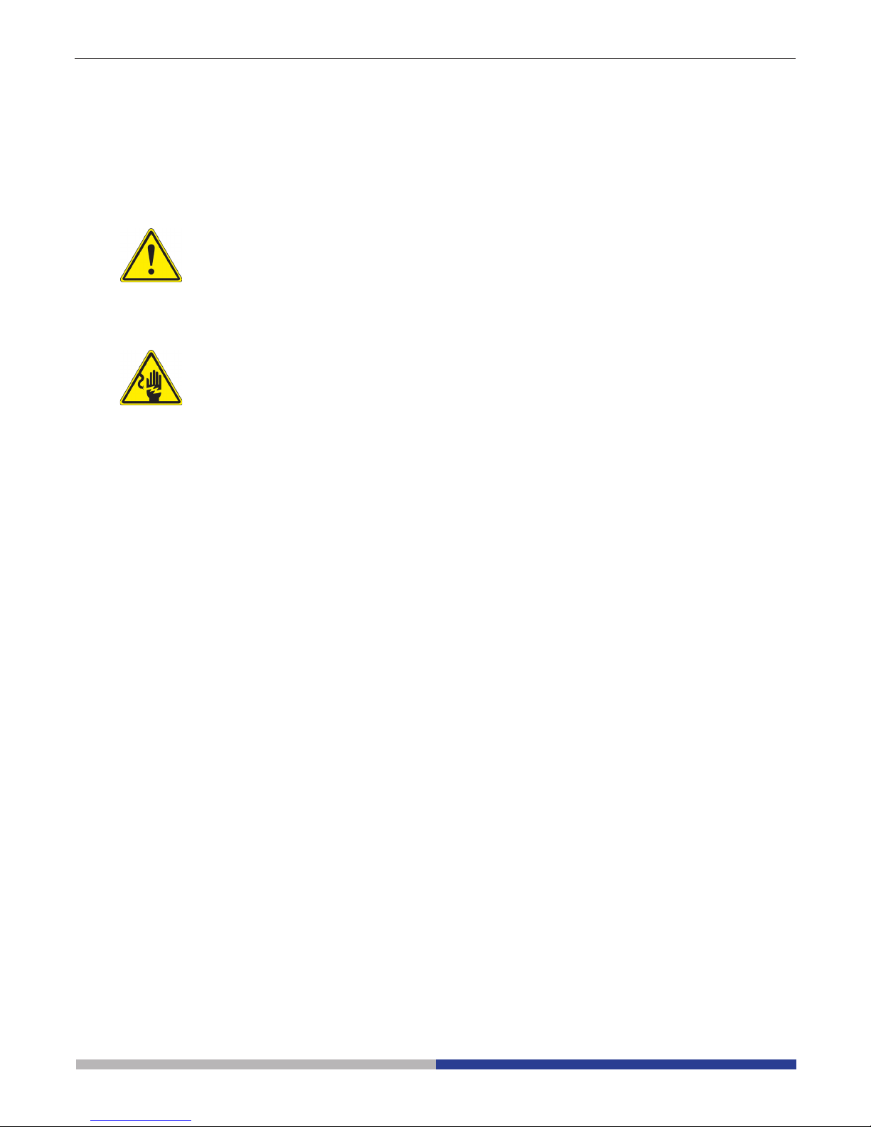
Overview
TRINOCULAR
VIEWING
TUBE
(FIXED)
DIOPTRIC
ADJUSTMENT
RING
EYEPIECE
PHASE CONTRAST SLIDER
(OPTIONAL FOR IM-3FL4)
LED
HOUSING
CONDENSER
FILTER HOLDER
COARSE
FOCUS KNOB
FINE FOCUS KNOB
FLUORESCENCE
POWER SUPPLY
TENSION
ADJUSTMENT
COLLAR
OBJECTIVE
STAGE
MICROSCOPE
BODY
LIGHT PATH
SELECTOR
LEVER
GLASS STAGE INSERT
Page 5
Page 5
Unpacking
The microscope is housed in a moulded Styrofoam container. Remove the tape from the edge of the container
and lift the top half of the container. Take some care to avoid that the optical items (objectives and eyepieces)
fall out and get damaged. Using both hands (one around the arm and one around the base), lift the microscope
from the container and put it on a stable desk.
Assembling
Once you open the box, these are the microscope’s components:
① Microscope body
② Condenser
③ LED illuminator
④ Fluorescence power supply
⑤ Power cables
⑥ Filter holder
⑦ Metal insert for stage
⑧ Glass insert for stage
⑨ Objectives
⑩ Eyepieces
⑪ Fluorescence lters
⑫ Brighteld lters (IF550)
⑬ Orange screen
⑭ Diaphragm assembly
⑮ Mercury lamp house
①
②
⑪
⑫
⑬ ⑭
⑮
⑩
③
④
⑤
⑥
⑦ ⑧
⑨
Page 6

Page 6
③
Fig.2
Fig.3
Fig.4
Fig.5
Fig.1
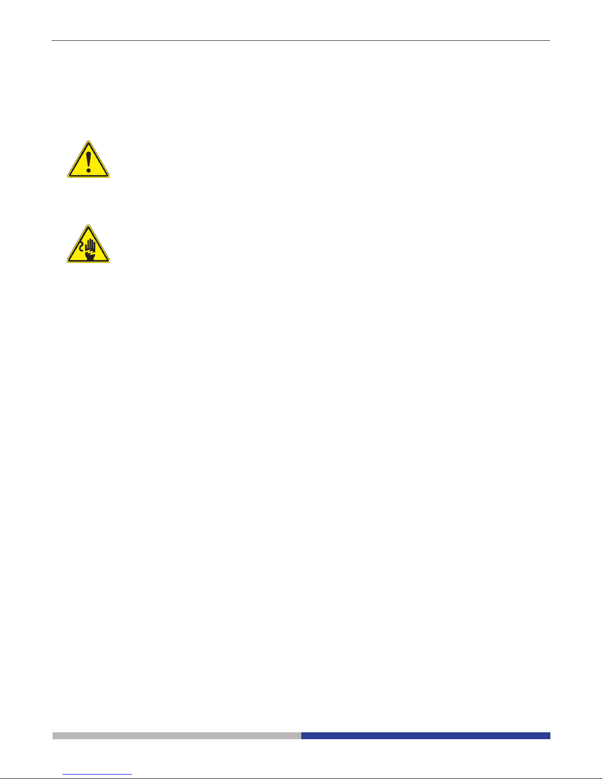
1. Turning the coarse focusing knob ① till the
nosepiece reaches its lowest position.
► For a safe transport, the nosepiece is
placed in the lowest position and the
tension adjustment collar ② is adjust-
ed to the appropriate tension when the
microscope leaves the factory. (Fig.1)
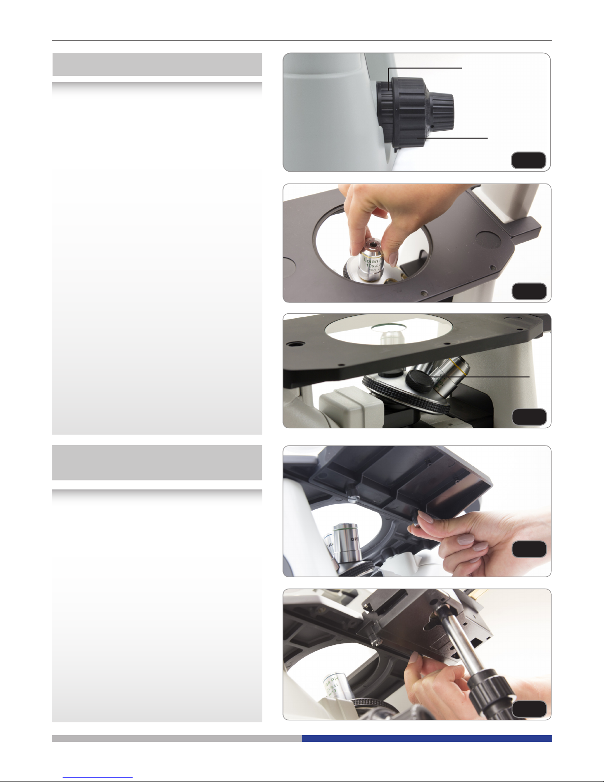
2. Screw the lowest magnication objective
on to the turret from the right side, then
turn the turret clockwise. Mount the other
objectives in the same way, following the
sequence from low to high.
► Note: the objectives can also be in-
stalled through the stage opening.
(Fig.2)
► Clean the objectives regularly. In inverted
microscopes, the objectives are very sensitive to dust.
► To prevent dust and contamination from
entering the microscope, cover all the unused holes with dust caps ③. (Fig.3)
► When operating, use the low magnication
objective (10X) to search and focus the
specimen, then switch to higher magnica-
tions.
► When switching between objectives, slowly
turn the nosepiece until it clicks. The click
means that the objective is in the right position, in the center of the light path.
①
②
Installing the objectives
The stage extension can be installed on either
side of the stage to enlarge the working surface. The mechanical stage must be installed
on the side opposite the extension.
For right-handed operators, the mechanical
stage is normally installed on the right side.
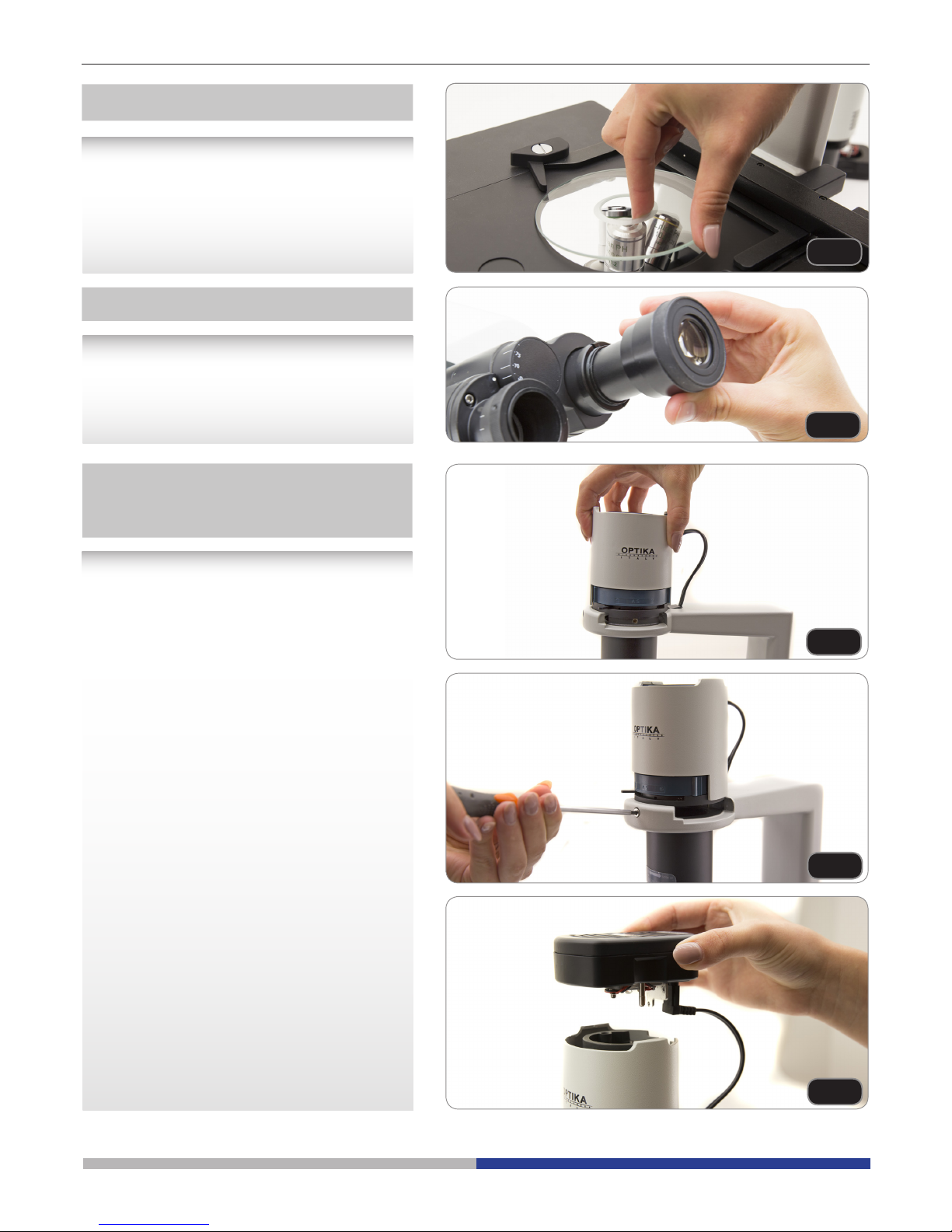
1. Installing the stage extension: Screw the
bolts on to the extension, then mount the
extension from below the stage. (Fig.4)
2. Installing the mechanical stage: As for the
extension, the mechanical stage is xed
with two bolts under the stage. (Fig.5)
Installing the stage extension and
the mechanical stage (OPTIONAL)
Page 7

Page 7
Page 7
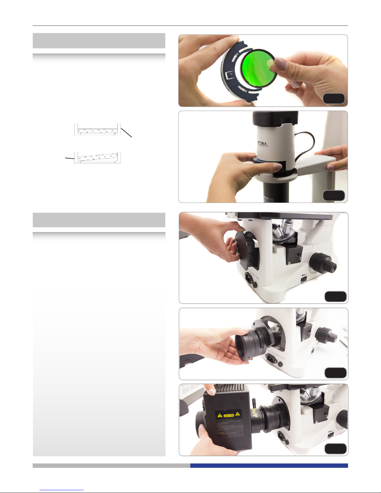
1. When using the glass stage, make sure
that the insert is horizontal.
2. Install the stage insert in the stage open-
ing. (Fig.6)
Installing the stage insert
Installing the eyepieces
Insert both eyepieces into the tubes of the
optical head. (Fig.7)
Fig.6
Fig.7
Fig.8
Fig.9
Fig.10
1. Insert the condenser illumination unit into
the bracket. (Fig.8)
2. Turn the condenser illumination unit clockwise about 90°, with the “AS” mark of lter
holder facing forwards. Align the screw of
the condenser illumination unit and the
hole of the holder, then screw the bolt in
the hole with the supplied allen wrench.
(Fig.9)
3. Insert the connector plug into the connec-
tor jack.
4. Push the LED housing gently into the
holes of the illumination unit. (Fig.10)
Installing the condenser
illumination unit and the LED
housing
Page 8

Page 8
► Remove the lter holder, then install the
color lters you need. (Fig.11, Fig.12)
Mount the color lter at as shown in ①,
verifying that they are not tilted.
► If the color lter is tilted or otherwise
out of place ②, it may fall.
The color lters can be stacked in the
holder. This allows to install as many lters
as needed, as long as the whole thickness
is less than 11 mm.
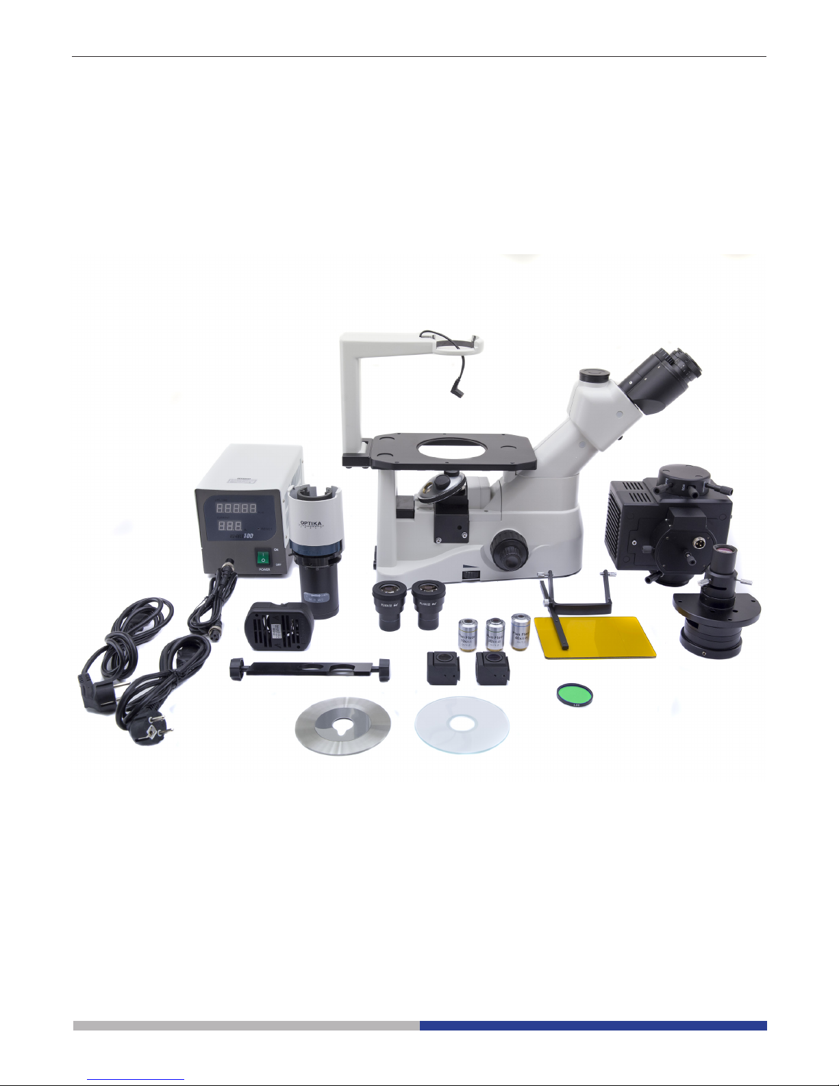
• Pull the black plastic cover out, from the
microscope rear. (Fig.13)
• Insert the lens/diaphragm assembly from
the back. In order to ease the insertion,
just tilt the assembly at about 45° and
move it forward. Fix it using the 3 provided
allen screws. (Fig.14)
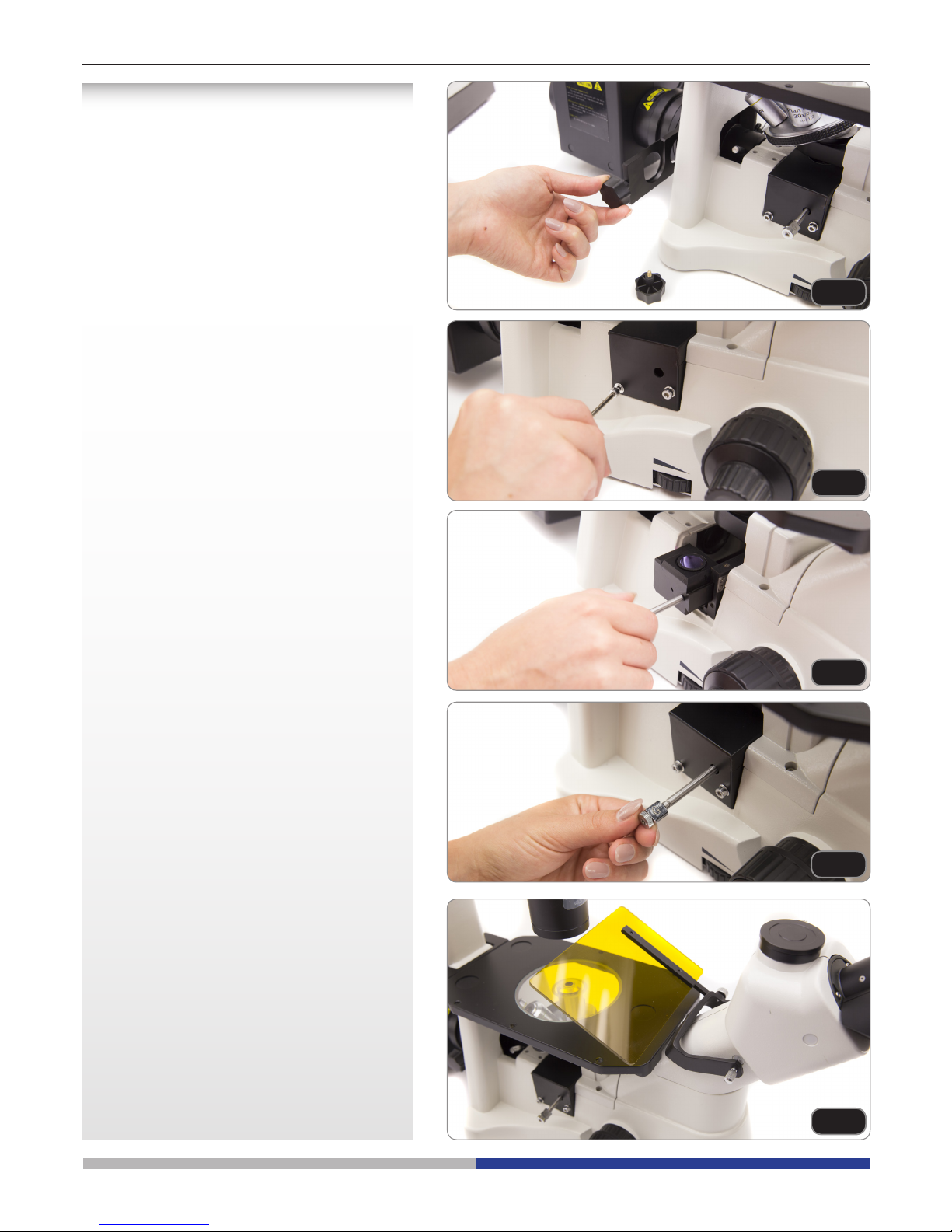
• Insert the lamp house and x it with the allen screw (already inside the support tube
(1) ). (Fig.15)
Installing the color lters
Installing the uorescence
Fig.11
Fig.12
Fig.13
Fig.14
Fig.15
①
②
Page 9
Page 9
• Insert the lter holder into its slot near the
lamp house. (Fig.16)
• Unscrew the protection cover on the left
side of the microscope, with the provided
allen wrench. (Fig.17)
• Slide the green lter inside the dovetail
guide, after screwing the lter lever into the
threaded hole of the lter. Mount the protection cover back in its position. (Fig.18)
• On top of the lter lever, screw the terminal
with the etched G. Repeat the same steps
for the right side, mounting the Blue lterset. (Fig.19)
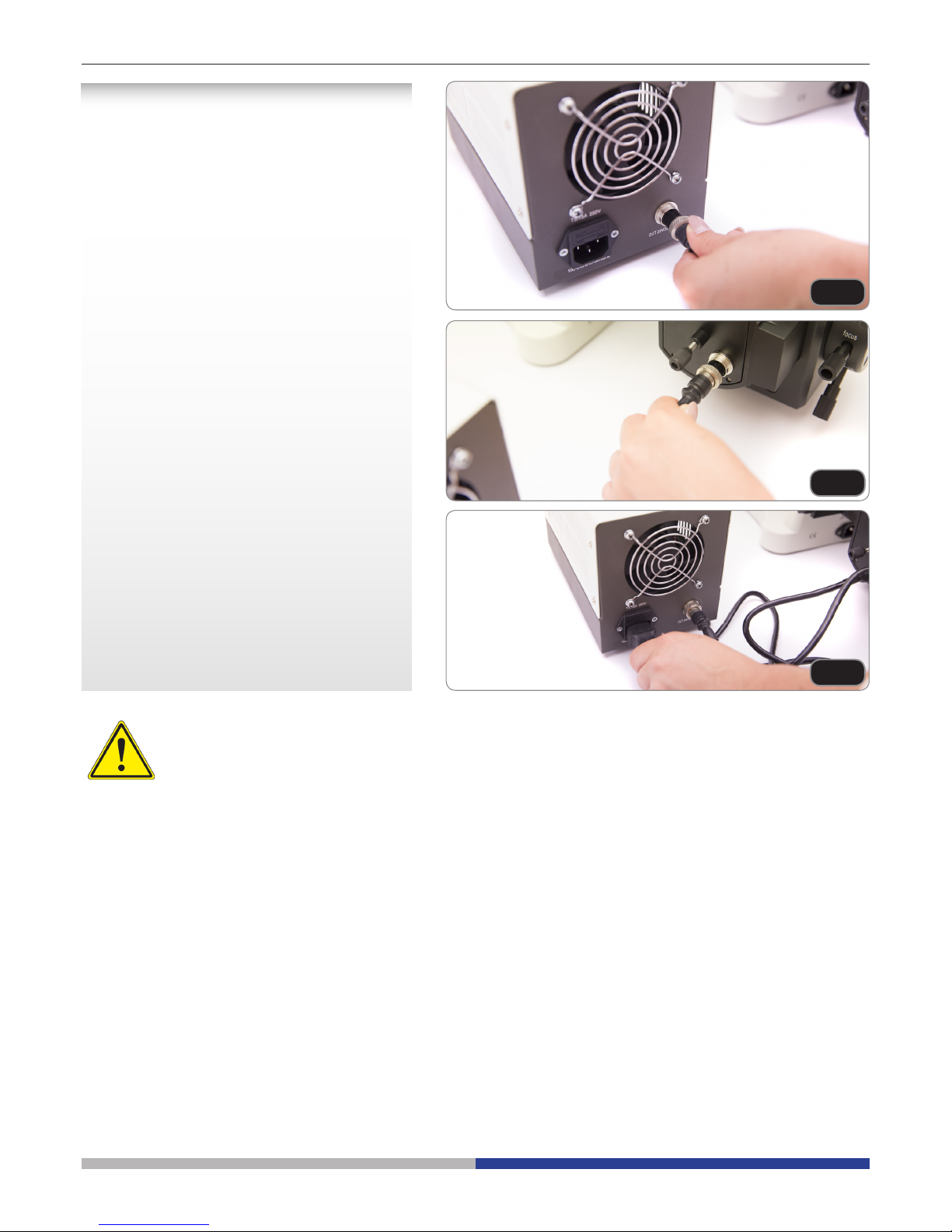
• For preventing possible damages from
UV radiation, mount the orange protection
screen as shown. (Fig.20)
Fig.16
Fig.17
Fig.18
Fig.19
Fig.20
Page 10
Page 10
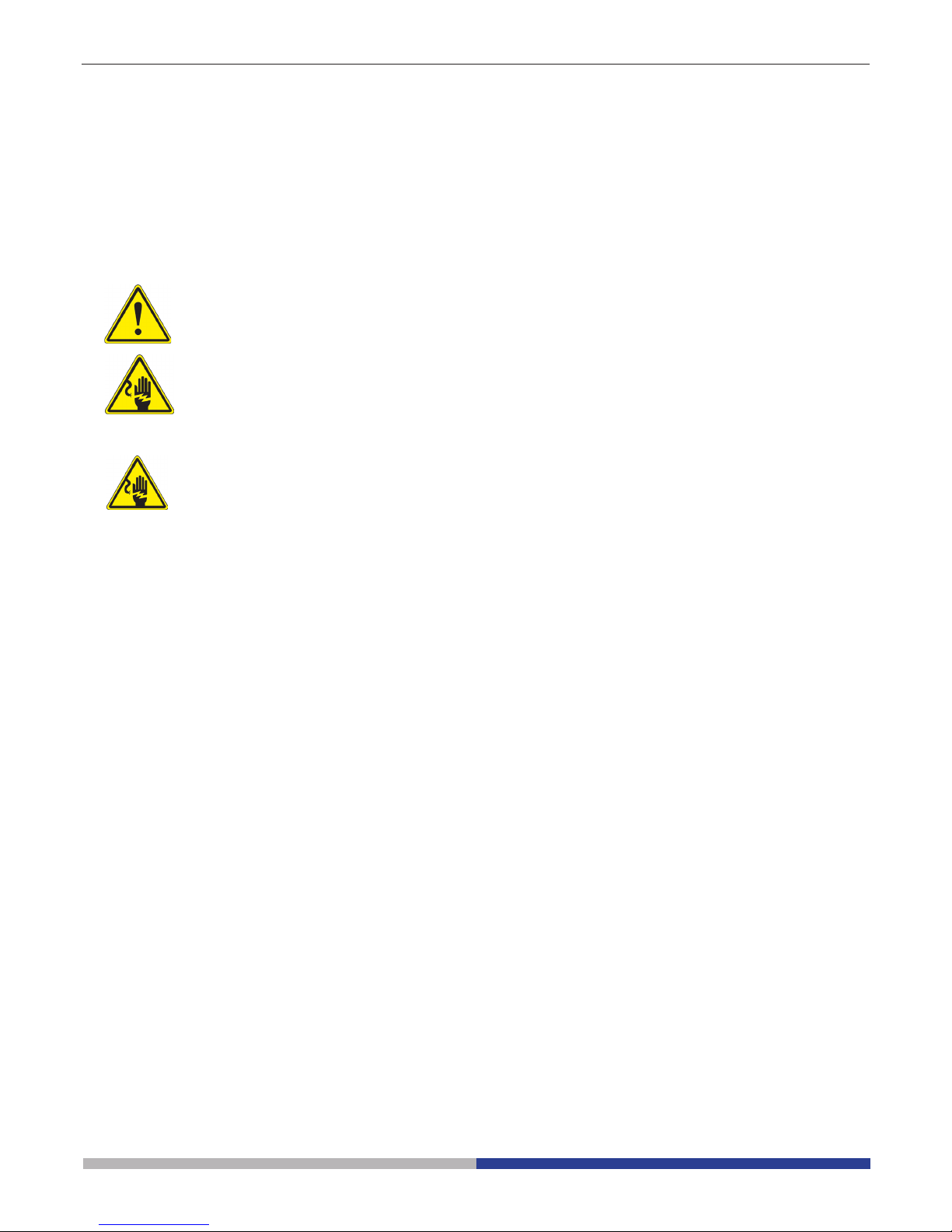
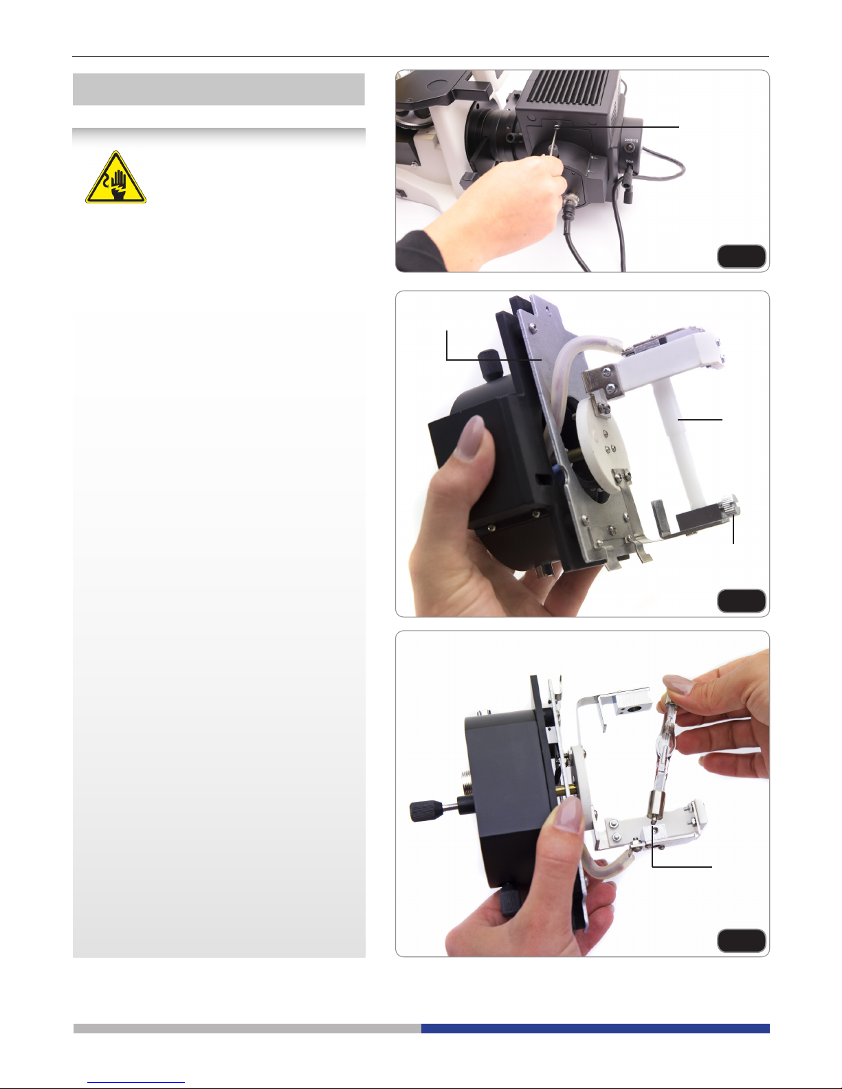
• Connect the cable from the external power
supply to the HBO lamp house. (Fig.21;
Fig.22)
• Connect the power cable to the external
power supply. (Fig.23)
Fig.21
Fig.22
Fig.23
• The input voltage for uorescence power supply is 110-240Vac.
• Please use the standard power cable provided by our company. Select suitable one when mis-
sing or damaged.
• Connect the power supply correctly, be sure to have a good earth connection.
Page 11
Page 11
Fig.24
Fig.25
Fig.26
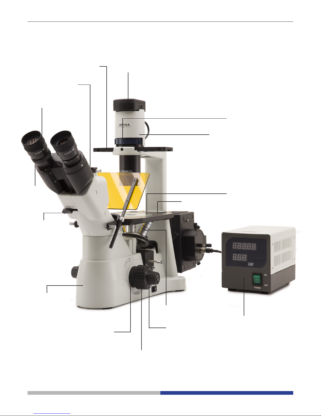
Mount or replace the mercury lamp
Before replacing the bulb, please set the uorescence power supply to (OFF) position and
unplug the power cable. Be sure that the lamp
has completely cooled down.
Loosen the lock-screw ① (Fig.24) completely
and take o the bulb holder ②. Loosen the
lock screw ③ and take o the plastic pole ④.
(Fig.25)
The HBO lamp has 2 poles of dierent dimensions, so that it ts in only one direction: insert
the anode pole (bigger one) into the xed holder ① and the other pole in the exible holder.
Then tighten the screw. (Fig.26)
Mount the lamp door back in place and tighten
the door locking screw.
②
③
④
①
①
Page 12

Page 12
1. Turn the main switch ① to “O”(o) before
connecting the power cord. (Fig.27)
2. Insert the cable into the power socket of
the microscope. (Fig.28)
3. Plug the power cord into the mains sock-
et. Check for a safe connection.
► Please use the supplied power cord.
If lost or damaged, please refer to
qualied service.
► Connect the power cord to a grounded
(earthed) power supply only.
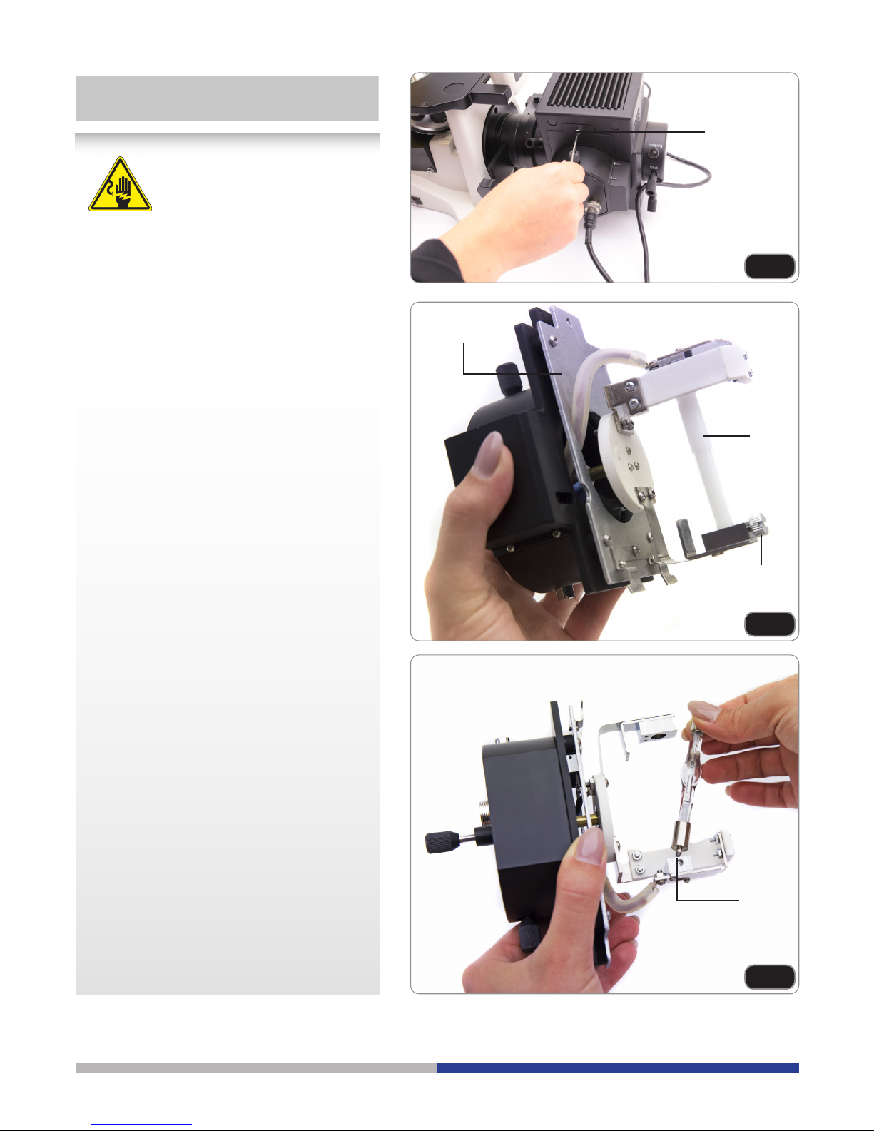
Before replacing the fuse, turn the main switch
to “O” (o) and unplug the power cord.
Rotate the fuse support out of the holder using
a straight screwdriver. Insert a new fuse in the
support, then rotate the support back into the
holder. (Fig.29)
► Fuse rating:
see back of the microscope.
Connecting the power cord
Replacing the fuse
Fig.27
Fig.28
Fig.29
①
Page 13

Page 13
Turning on the LED
Connect the power, turn on the main switch ①.
(Fig.30)
Adjusting the brightness
Turn the brightness adjustment knob ② to in-
crease and decrease the brightness. (Fig.31)
Adjusting the tension
► The coarse focusing knob ① is pre
adjusted to a tight tension upon leaving the factory.
If the nosepiece drops down by itself, or the
specimen defocuses while adjusting the ne
focus knob ③, the coarse focus knob is too
loose. Turning the tension adjustment collar ②
in clockwise direction tightens the coarse focus tension ①. Rotate in the opposite direction
to decrease the tension. (Fig.32)
Setting the specimen
► For the best image quality, use asks,
Petri dishes and slides with a 1.2 mm
thickness.
1. Place the proper insert for your specimen
(according to the table on the right) on the
stage, and x it with the stage clip.
2. Turning the X and Y knobs, move the
specimen to the required position. (Movement Range: 120 (width) × 78 (length)
mm).
Moving the specimen
Move the specimen to the desired position by
freehand or by turning the knobs of the mechanical stage.
► When switching objectives, take care
not to touch the adaptor plates with
the objectives, as their weight may
damage the front lens.
M-793.1
Holder for Petri diameter 38mm (M-793.2 needed)
M-793.2
Holder for Terasaki and Petri diameter 65mm.
M-793.3
Holder for slide and Petri diameter 54mm.
M-793.4
Holder for 2+2 slides.
M-793.6
Holder for Utermöhl-Chamber (M-793.3 needed).
M-792
Mechanical stage for IM-3 series.
INITIAL SETUP
STAGE (OPTIONAL)
Using the microscope
Fig.30
Fig.31
①
②
①
②
③
Fig.32
M-793.7
Load-bearing side extension for IM-3 series.
Page 14
Page 14
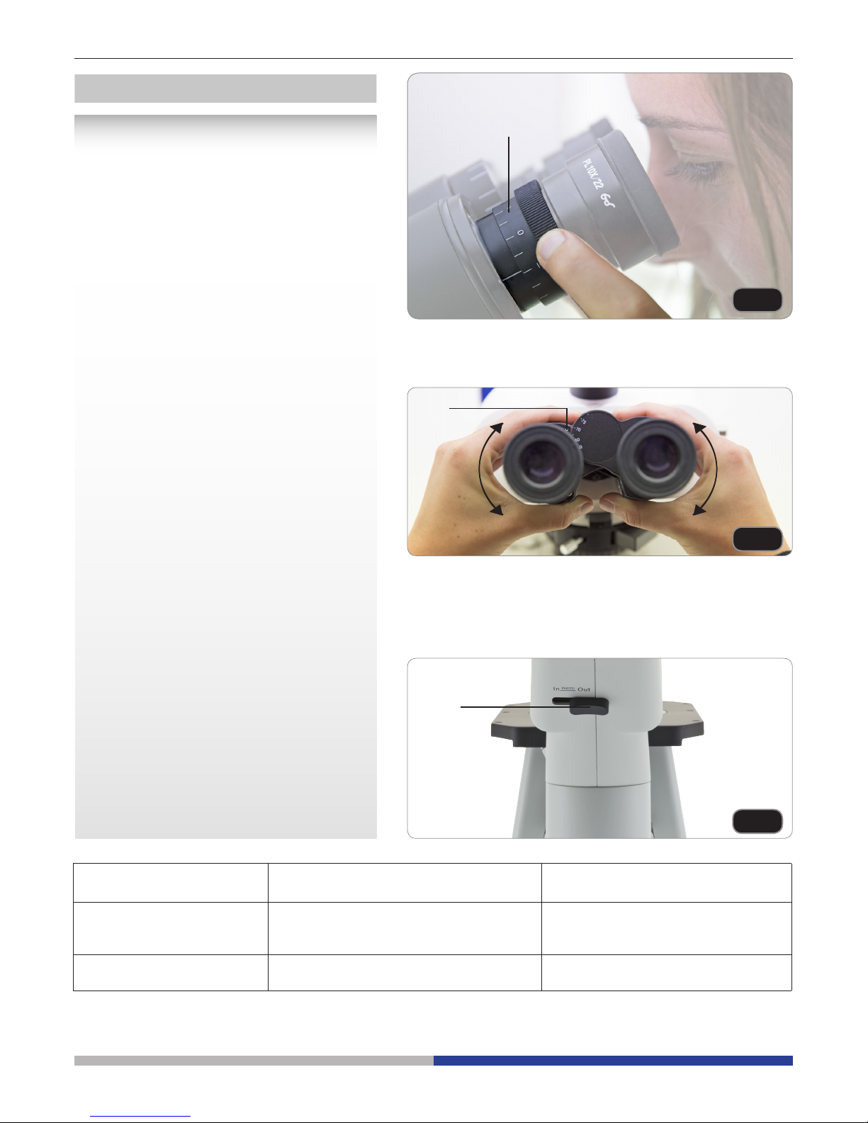
Dioptric adjustment
1. Look into the right eyepiece with your right
eye only, and focus on the specimen.
2. Look into the left eyepiece with your left
eye only. If the image is not sharp, use
the dioptric adjustment ring ① to compen-
sate. (Fig.33)
► The adjustment range is ±5 diopter.
The number indicated on the adjustment ring graduation should correspond to the operator’s dioptric correction.
Adjusting the interpupillary distance
Observing with both eyes, hold the two eyepiece prism assemblies. Rotate them around
their common axis until the elds of view coincide.
► The graduation on the interpupillary
distance indicator ②, pointed by the
spot “.” on the eyepiece holder, shows
the distance between the operator’s
eyes. (Fig.34)
The range of the interpupillary distance is 48-
75mm.
Selecting the light path
Pull the light path selector lever ③ sideways
using your thumb, selecting the light path you
need. (Fig.35)
VIEWING TUBE
②
Fig.33
Fig.34
Fig.35
LIGHT PATH SELECTOR
LEVER
BRIGHTNESS APPLICATION
In 20% used for binocular observation, and
80% used for video or photography
Binocular observation, television, and
micrography or video can be operated
simultaneously
Out 100% used for binocular
observation
Binocular
observation
③
①
Page 15

Page 15
Using color lters
Selecting the appropriate color lters according your need. (Fig.36)
You can stack a group of color lters in the lter holder, if you ensure that they are level and
that the whole thickness is less than 11mm.
Using the aperture diaphragm
When in brighteld observation, the aperture
diaphragm controls the numerical aperture of
the illumination system. When the numerical
aperture of the objective and the aperture of
the illumination system match, the highest resolution is achieved.
The aperture can be changed by moving the
aperture adjustment lever. ① is the image of
the aperture diaphragm, ② is the edge of the
objective).
Generally, when observing a fully chromatic
specimen, you need to set the size of the condenser to 70-80% of the aperture of the objective. When observing unstained samples (e.g.
bacteria), start from 70% and slowly turn the
aperture diaphragm lever clockwise. (Fig.37)
ILLUMINATION UNIT
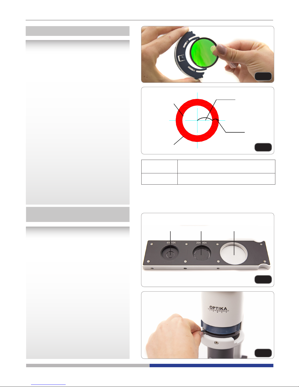
Phase contrast slider
Adjustable phase slider.
● The light ring is pre-centered when the
microscope leaves the factory. It should
therefore need no further adjustment. If a
recentering is needed, it can be performed
via the two side bolts.
● The 4x/10x light ring ① must be used with
4x and 10x phase contrast objectives, the
20x/40x light ring ② with the 20x and 40x
and the opening ③ is used for bright eld.
(Fig.38)
Installing the phase contrast slider
1. Insert the slider into the illumination
system, printed face up.
2. Pull the slider into the desired position, to
the click stop.
3. When in phase contrast observation, keep
the aperture diaphragm adjustment lever
on the “O” (open) position. (Fig.39)
PHASE CONTRAST
(
OPTIONAL FOR IM-3FL4
)
Fig.36
Fig.38
Fig.39
Fig.37
70-
30-
70-80%
30-20%
COLOR
FILTER
USE
Green Single contrast color lter used for phase
contrast microscopy
①
①
②
②
③
Page 16
Page 16
Fig.40
Fig.41
Fig.42
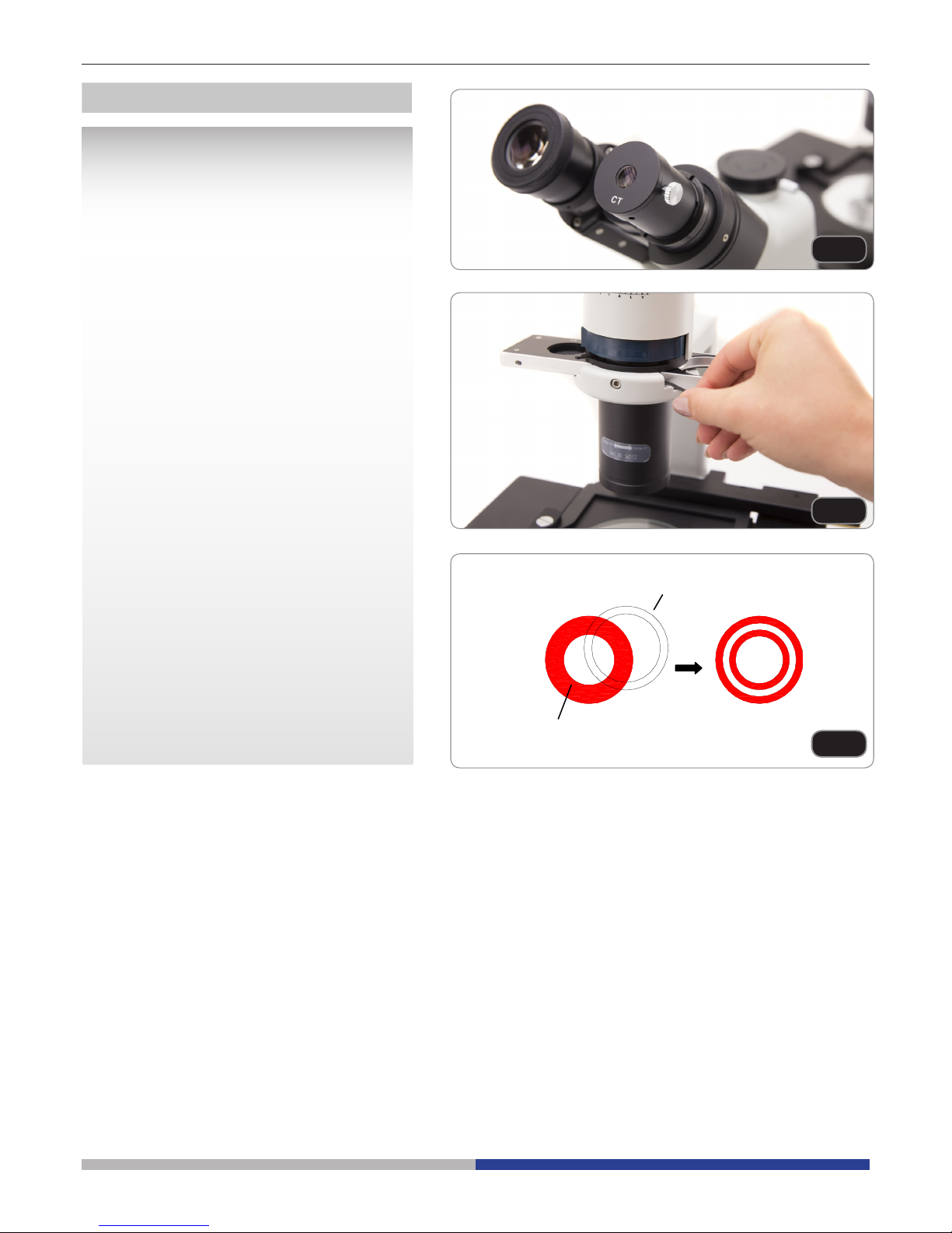
Centering the ring
► Usually this operation is not needed. If
necessary, please proceed with the following steps:
1. Place a specimen on the stage and focus
it.
2. Take out the eyepiece from the tube without the dioptric adjustment, and replace it
with the centering telescope (CT). (Fig.40)
3. Check that the phase ring and the objective
correspond, and that both are steadily set
on a click stop.
4. Use the CT to focus on the light ring’s im-
age ① and the phase contrast ring’s image
②. If the light ring’s image is not sharp, ad-
just the CT’s eyepiece until you can see a
clear image of the light ring.
5. Adjust the bolts of the two centering holes
in the phase contrast slider using a screwdriver until the light ring center and the
phase contrast ring center coincide.
6. The 10x and the 20x phase contrast objectives use the same ring on the phase contrast slider. The coincidence of the light ring
center and the phase contrast center must
be veried with both objectives.
(Fig.41; Fig.42)
► If the light ring is centered incorrectly,
the contrast will be severely impaired.
► The phase ring may need recentering
during and after observation of very
thick specimens.
► The phase ring may show an apparent
misalignment if the cover glass is not
at.
①
②
Page 17

Page 17
Fig.45
Fig.43
Fig.44
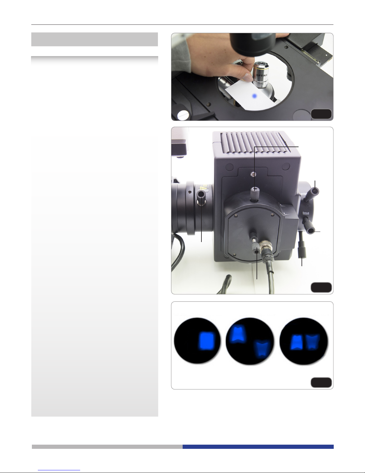
Centering mercury bulb
After turning on the uorescence power
supply, let the HBO lamp reach the thermal
stability (at least 5 minutes) before pro-
ceeding to the alignment.
Turn the nosepiece to an empty position without objective, and place a piece of white paper
directly on the hole. (Fig.43)
Pull the lter selection lever until the blue lterset is inserted into the light path.
Open the eld diaphragm completely.
(Fig.44) Adjust the lamp focusing knob ①, ver-
tical adjusting screw ②, horizontal adjusting
screw ③ in order to get an image of the bulb
on the white paper, similar to Fig.45 Ⓐ.
(Fig.44) Adjust the focusing screw ④ for the
back reecting mirror, horizontal centering
screw ⑤, vertical centering screw ⑥, in order
to get an image of the bulb’s reection on the
white paper, similar to Fig.45 Ⓑ.
(Fig.44) Continue to adjust the screws of the
back reecting mirror until you obtain a symmetrical image of the bulb and its reection,
both very near the center of the light path Fig.
45 Ⓒ.
①
Ⓐ Ⓑ Ⓒ
②
③
④
⑤
⑥
Page 18
Page 18
Fig.46
Fig.47
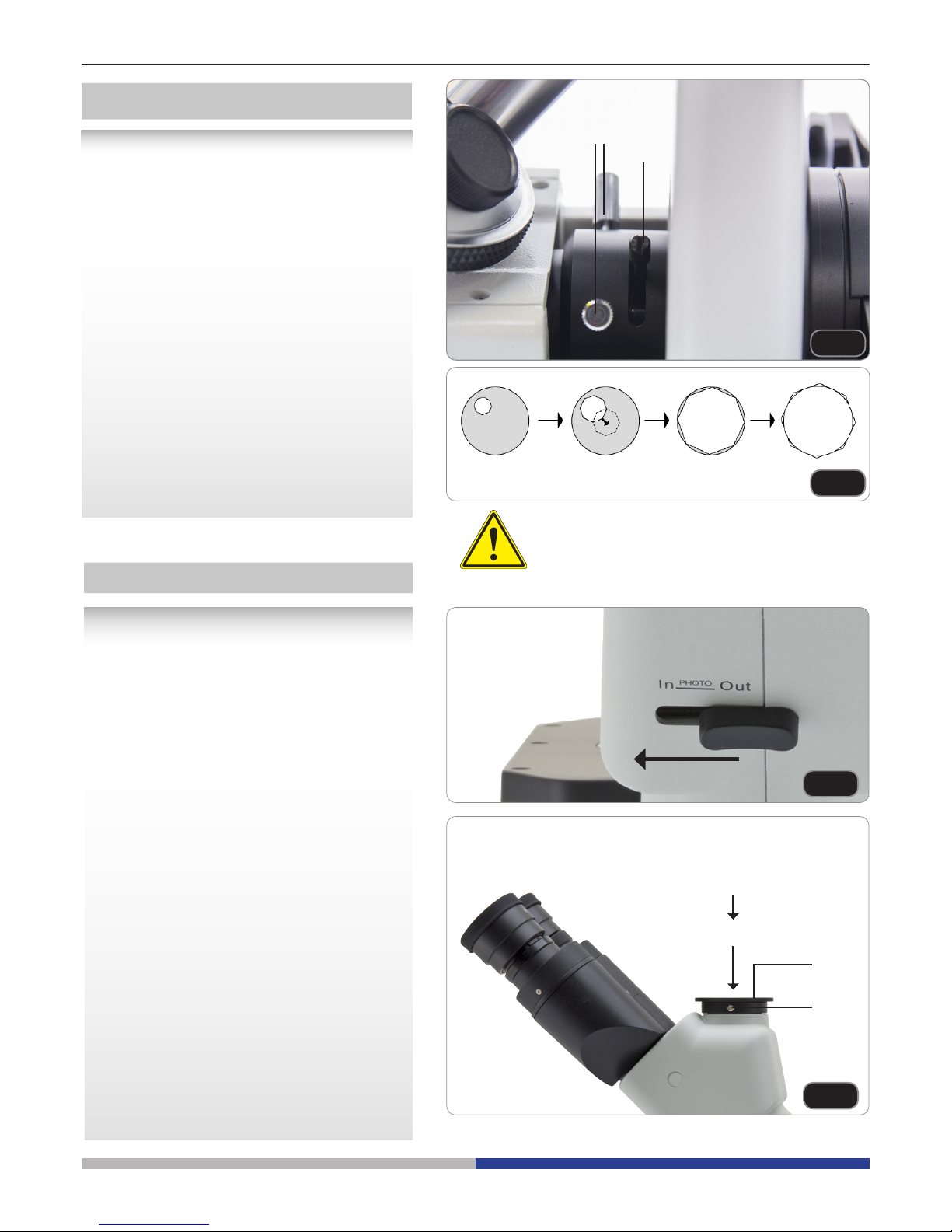
View eld diaphragm
Field diaphragm limits the light beam diameter
on the specimen plane, therefore eliminates
the stray light in order to enhance image contrast. When the eld diaphragm image is just
at the edge of the eld of view, the system can
provide the best performance.
Turn the adjusting lever ① of eld diaphragm
clock-wise to open the diaphragm, otherwise
to close it. (Fig. 46)
Adjust the screws ② at both sides of the eld
diaphragm to center the image of the diaphragm itself. (Fig. 46)
Open the eld diaphragm gradually, if the image of eld diaphragm is just inscribed to the
eld of view, this means that the eld diaphragm has been centered. (Fig.47)
In order to prevent the specimen from uorescence quenching, don’t expose the same
portion of the specimen for too long.
①
②
Installing the photography adapter
1. To activate the video port, pull the light
path selector lever to “In” position. (Fig.48)
2. Loosen the locking bolt ① on the trinocular viewing tube, and take out the dust cap
②.
3. Install the photography adapter into the
trinocular port according to its instructions,
and screw down the locking bolt ①.
4. Attach the camera ring (if any) to the
adapter.
5. Attach the camera to the ring.
● Warning: for some cameras (mainly reex) the ring is not included with the microscope, and it should be supplied by the
user.
● For the photography of dark specimens,
obscure the eyepieces and the viewnder
with a dark cloth in order to reduce stray
light.
● The camera magnication can be calculated as objective magnication × camera
+ lens magnication.
► When shooting with a SLR, the mirror
movement may cause camera movement. Please lift the mirror, use long
exposure times and use an extension
cord. (Fig.49)
MICROPHOTOGRAPHY
Fig.48
Fig.49
①
Camera
Adapter
②
Page 19
Page 19
Maintenance
Microscopy environment
This microscope is recommended to be used in a clean, dry and shock free environment with a temperature of
5°-40°C and a maximum relative humidity of 75 % (non condensing). Use a dehumidier if needed.
To think about when and after using the microscope
• The microscope should always be kept vertically when moving it and be careful so that no
moving parts, such as the eyepieces, fall out.
• Never mishandle or impose unnecessary force on the microscope.
• Never attempt to service the microscope yourself.
• After use, turn o the light immediately, cover the microscope with the included
dust-cover, and keep it in a dry and clean place.
Electrical safety precautions
• Before plugging in the power supply, make sure that the supplying voltage of your region
matches with the operation voltage of the equipment and that the lamp switch is in o-
position.
•
Users should observe all safety regulations of the region. The equipment has acquired
the CE safety label. However, users do have full responsibility to use this equipment safely.
Cleaning the optics
• If the optical parts need to be cleaned try rst to: use compressed air.
• If that is not sucient: use a soft lint-free piece of cloth with water and a mild detergent.
• And as a nal option: use the piece of cloth moistened with a 3:7 mixture of ethanol and ether.
Note: ethanol and ether are highly ammable liquids. Do not use them near a heat source, near sparks or
near electric equipment. Use these chemicals in a well ventilated room.
• Remember to never wipe the surface of any optical items with your hands. Fingerprints can damage the
optics.
• Do not disassemble objectives or eyepieces in attempt to clean them.
For the best results, use the OPTIKA cleaning kit (see catalogue).
If you need to send the microscope to Optika for maintenance, please use the original packaging.
Page 20

Page 20
Troubleshooting
Review the information in the table below to troubleshoot operating problems.
PROBLEM CAUSE SOLUTION
I. Optical Section:
The illumination is open, but the eld
of view is dark.
The plug of the LED holder is
not connected to the illumina-
tion set
Connect them
The brightness is too low Adjust to a proper setting
Too many colour lters have
been stacked
Minimize the number of the lters
The edge of the eld of view is
vignetted or the brightness is asym-
metric.
The nosepiece is not in the correct position
Turn the nosepiece to a click stop
The color lter is partially
inserted
Insert the lter to full depth
The phase contrast slider is not
in the proper position
Move the slider to a click stop
Dust and stains can be seen in the
eld of view.
There are stains and dust on
the specimen
Clean the specimen
There are stains and dust on
the eyepiece
Clean the eyepiece
There is an apparent double image. The size of the aperture dia-
phragm is too small
Open the aperture diaphragm
Poor image quality:
The image is not sharp
The contrast is not high
The details are not clear
The phase contrast is low.
The nosepiece is not in the
center of the light path
Turn the nosepiece to a click stop
The aperture diaphragm in
the view of eld is opened too
much or too little
Adjust the aperture diaphragm
The lenses (condenser, objective, eyepieces are culture
dish) is dirty
Thoroughly clean all the optical system
In phase contrast observation,
the bottom thickness of the
sample is more than 1.2mm
Use a sample holder whose bottom thickness is less than 1.2mm
A bright eld objective is used
for phase contrast observation
Switch to a phase contrast objective
The condenser ring is not
aligned with the objective
phase ring
Adjust the condenser ring to match the
objective phase ring
The light ring and/or the phase
contrast ring is not centered
Adjust the bolts to center them
The objective used is not compatible with the phase ring
Please use a compatible objective
The phase contrast depends on
the sample position
The sample holder is not at. Move the
sample around until a compatible area is
found.
Page 21

Page 21
One side of the image is out of focus. The nosepiece is not in the
center of the light path
Turn the nosepiece to a click stop
The specimen is out of place
(tilted)
Place the specimen at on the stage.
The optical performance of the
sample cover glass is poor
Use a cover glass of better quality
II. Mechanical Section:
The coarse focus knob is hard to
turn.
The tension adjustment collar is
too tight
Loosen the tension adjustment collar
The focus is unstable. The tension adjustment collar is
too loose
Tighten the tension adjustment collar
III. Electric section
The LED doesn’t turn on. No power supply Check the power cord connection
The brightness is not enough The brightness adjustment is
low
Adjust the brightness
The light blinks The power cord is poorly con-
nected
Check the power cord
IV. Viewing tube assembly
The eld of view of the two eyes is
dierent
The interpupillar distance is not
correct
Adjust the interpupillar distance
The dioptric correction is not
right
Adjust the dioptric correction
The viewing technique is not
correct, and the operator is
straining the eyesight
When look into the objective, do not stare
at the specimen but look at the whole eld
of view. Periodically, move the eyes away
to look at a distant object, then back into
the objective
V. Microphotography and video
The image is unfocused Incorrect focussing Adjusting the focus system as in the pres-
ent manual
The edge of the image is unfocussed To some degree, it is inherent
to the nature of achromatic
objectives
The problem can be minimized by a correct
setting of the aperture diaphragm
Bright patches appear on the image Stray light is entering the
microscope through the eyepieces and through the camera
viewnder
Cover the eyepieces and the viewnder
with a dark cloth
Page 22

Page 22
Equipment disposal
Art.13 Dlsg 25 july 2005 N°151. “According to directives 2002/95/EC, 2002/96/EC and 2003/108/EC relating
to the reduction in the use of hazardous substances in electrical and electronic equipment and waste disposal.”
The basket symbol on equipment or on its box indicates that the product at the end of its useful life should be
collected separately from other waste.
The separate collection of this equipment at the end of its lifetime is organized and managed by the producer.
The user will have to contact the manufacturer and follow the rules that he adopted for end-of-life equipment
collection.
The collection of the equipment for recycling, treatment and environmentally compatible disposal, helps to prevent
possible adverse effects on the environment and health and promotes reuse and/or recycling of materials of the
equipment.
Improper disposal of the product involves the application of administrative penalties as provided by the laws in force.
Page 23

v 1.0 2017
Modello
IM-3F
IM-3FL4
Serie IM
MANUALE D’ISTRUZIONI
Page 24

Pagina 24
Indice Contenuti
Avvertenza
Simboli
Informazioni sulla sicurezza
Utilizzo previsto
Descrizione dello strumento
Disimballagio
Assemblaggio
Istruzioni per l’uso
Manutenzione
Risoluzione problemi
Smaltimento
Page 25

Pagina 25
Avvertenza
Questo microscopio è uno strumento scientico di alta precisione, progettato per durare a lungo con una minima
manutenzione; la realizzazione è secondo i migliori standard ottici e meccanici, per poter essere utilizzato
quotidianamente. Vi ricordiamo che questo manuale contiene informazioni importanti per la sicurezza e per la
manutenzione dello strumento, e deve quindi essere messo a disposizione di coloro che lo utilizzeranno.
Decliniamo ogni responsabilità derivante da un utilizzo dello strumento non indicato nel presente manuale.
Simboli
La seguente tabella riporta i simboli utilizzati in questo manuale.
PERICOLO
Questo simbolo indica un rischio potenziale ed avverte di procedere con cautela.
SHOCK ELETTRICO
Questo simbolo indica un rischio di shock elettrico.
Informazioni sulla sicurezza
Per evitare shock elettrici
Prima di collegare il cavo di alimentazione alla presa elettrica, assicurarsi che il voltaggio della rete locale
coincida con il voltaggio dello strumento e che l’interruttore dell’illuminazione sia nella posizione “O”.
Gli utenti dovranno seguire tutte le norme di sicurezza locali. Lo strumento è certicato CE. In ogni caso, gli
utilizzatori sono gli unici responsabili per un utilizzo sicuro dello strumento. Per l’utilizzo in sicurezza dello
strumento è importante attenersi alle seguenti istruzioni e leggere il manuale in tutte le sue parti.
Utilizzo previsto
Solo per ricerca. Non è previsto alcun utilizzo di questo strumento per uso diagnostico.
Page 26

Pagina 26
Descrizione dello strumento
TUBO DI USCITA
TRINOCULARE
ANELLO DI
REGOLAZIONE
DIOTTRICA
OCULARI
SLIDER PER
CONTRASTO DI FASE
(OPZIONALE PER IM-3FL4)
ALLOGGIAMENTO
LED
CONDENSATORE
PORTA-FILTRI
MANOPOLA DI
REGOLAZIONE DELLA
MESSA A FUOCO
MACROMETRICA
MANOPOLA DI
REGOLAZIONE
DELLA MESSA A
FUOCO
MICROMETRICA
ALIMENTATORE
FLUORESCENZA
ANELLO DI
REGOLAZIONE
DELLA
TENSIONE
OBIETTIVI
TAVOLINO
BASE DEL
MICROSCOPIO
SELEZIONATORE
PERCORSO
LUMINOSO
INSERTO PORTAPREPARATI
IN VETRO
Page 27

Pagina 27
Disimballagio
Il microscopio è riposto in un imballo di polistirolo espanso. Rimuovere il nastro adesivo dal collo ed aprire la
parte superiore dell’imballo. Fare attenzione a non far cadere le parti ottiche (obiettivi e oculari) nell’estrarre il
microscopio dalla scatola per evitare che vengano danneggiati. Utilizzare entrambe le mani (una intorno allo
stativo e una alla base), slare il microscopio dal contenitore e appoggiarlo su un piano stabile.
Assemblaggio
All’apertura della scatola, i componenti del microscopio sono i seguenti:
① Stativo microscopio
② Condensatore
③ Illuminatore LED
④ Alimentatore uorescenza
⑤ Cavo di alimentazione
⑥ Porta-ltri
⑦ Portapreparati in metallo
⑧ Portapreparati in vetro
⑨ Obiettivi
⑩ Oculari
⑪ Filtri uorescenza
⑫ Filtro campo chiaro (IF550)
⑬ Schermo protettivo arancio
⑭ Blocco con diaframma
⑮ Alloggiamento lampada HBO
①
②
⑪
⑫
⑬ ⑭
⑮
⑩
③
④
⑤
⑥
⑦ ⑧
⑨
Page 28
Pagina 28
③
Fig.2
Fig.3
Fig.4
Fig.5
Fig.1
①
②
1. Ruotare la manopola di regolazione macro-
metrica ① nché la torretta portaobiettivi si
trova nella posizione più bassa.
► Per garantire la sicurezza durante il tra-
sporto, prima della spedizione la torretta viene messa nella posizione più bassa e si sistema l’anello di regolazione
della tensione ② nella tensione appro-
priata. (Fig.1)
2. Avvitare l’obiettivo con minore potere di ingrandimento sulla torretta dal lato destro,
quindi ruotare la torretta in senso orario.
Montare gli altri obiettivi nello stesso modo,
dall’obiettivo con potere di ingrandimento
minore a quello maggiore.
► Nota: è possibile installare gli obiettivi
anche attraverso l’apertura del piano
portapreparati. (Fig.2)
► Tenere gli obiettivi puliti. Nei microscopi ro-
vesciati gli obiettivi sono molto sensibili alla
polvere.
► Per evitare polvere e contaminazioni, co-
prire tutti i fori non utilizzati con gli appositi
tappi antipolvere ③. (Fig.3)
► Durante l’uso, servirsi degli obiettivi con
minor potere di ingrandimento (10X) per
guardare e mettere a fuoco i preparati,
quindi aumentare il potere di ingrandimen-
to.
► Per passare da un obiettivo a un altro,
ruotare lentamente il revolver nché non
scatta. Lo scatto avverte che l’obiettivo è in
posizione corretta, al centro del percorso
luminoso.
Installazione degli obiettivi
Il prolungamento può essere montato su
entrambi i lati del piano portapreparati per
aumentare la supercie
di lavoro. Il tavolo traslatore va installato sul
lato opposto a quello del prolungamento.
Per operatori destrimani, solitamente il tavolo
traslatore si installa sul lato destro.
1. Installazione del prolungamento del piano:
Anzitutto avvitare i bulloni al prolungamento,
quindi montare il prolungamento da sotto il
piano portapreparati. (Fig.4)
2. Installazione del tavolo traslatore: Come
per il prolungamento, anche il tavolo
traslatore è ssato da due bulloni sotto il
piano. (Fig.5)
Installazione del prolungamento del
piano e del tavolo traslatore (OPZIONALE)
Page 29
Pagina 29
Page 29
Fig.6
Fig.7
Fig.8
Fig.9
Fig.10
1. Assicurarsi che il piano portapreparati sia
perfettamente orizzontale quando si usa il
piano in vetro.
2. Inserire l’inserto in vetro nell’apertura del
piano. (Fig.6)
Installazione dell’inserto in vetro
Installazione degli oculari
Togliere il tappo ai tubi portaoculari, inserire gli
oculari nei tubi. (Fig.7)
1. Inserire il gruppo condensatoreilluminatore nell’apposito braccio. (Fig.8)
2. Ruotare il gruppo in senso orario di circa
90°: il marchio “AS” del portaltri deve
essere rivolto in avanti. Allineare la vite del
gruppo condensatore-illuminatore con il
foro nel portaltri, quindi avvitare il bullone
nel foro servendosi dell’apposita chiave
esagonale inclusa nel kit.. (Fig.9)
3. Inserire il cavo di alimentazione nel
connettore jack.
4. Inserire il portalampada spingendolo
con molta cura nei fori del gruppo di
illuminazione. (Fig.10)
Installazione del gruppo
condensatore-illuminatore e
dell’alloggiamento LED
Page 30
Pagina 30
• Estrarre dal retro del microscopio il
coperchio plastico nero. (Fig.13)
• Inserire il blocco diaframma dal retro. Per
facilitarne l’inserimento, orientarlo a 45° e
quindi inserirlo. Fissare il blocco tramite le
3 viti a brugola fornite. (Fig.14)
• Inserire l’alloggiamento della lampada
HBO e ssarla tramite vite a brugola (che
si trova già avvitata nel tubo di supporto).
(Fig.15)
Installazione uorescenza
Fig.11
Fig.12
Fig.13
Fig.14
Fig.15
► Togliere il portaltro, quindi inserire
il ltro cromatico desiderato. (Fig.11,
Fig.12)
Il ltro cromatico va montato piano come in
gura ①, vericare che non sia inclinato.
► Se il ltro cromatico è inclinato o
comunque fuori posto ②, rischia di
cadere.
I ltri cromatici possono essere sovrapposti
nel portaltri, permettendo così di inserire
tutti i ltri necessari nché lo spessore
resta inferiore a 11 mm.
Installazione dei ltri cromatici
①
②
Page 31

Pagina 31
• Inserire il porta-ltri nello slot vicino all’alloggiamento della lampada HBO. (Fig.16)
• Svitare il coperchio di protezione alla sinistra dello stativo, con la chiave a brugola
fornita. (Fig.17)
• Fare scorrere il portaltro verde lungo la
guida a coda di rondine, dopo aver avvitato l’astina sul portaltro. Rimontare il coperchio di protezione. (Fig.18)
• Avvitare sull’estremità dell’astina il terminale con la scritta “G” incisa. Ripetere
i medesimi passi sulla parte destra per il
ltro blu. (Fig.19)
• Per prevenire eventuali danni da radiazione UV, montare lo schermo di protezione
arancio come indicato. (Fig.20)
Fig.16
Fig.17
Fig.18
Fig.19
Fig.20
Page 32

Page 32
• Connettere il cavo dall’alimentatore ester-
no verso l’alloggiamento della lampada
HBO. (Fig.21; Fig.22)
• Connettere il cavo di alimentazione all’ali-
mentatore esterno. (Fig.23)
Fig.21
Fig.22
Fig.23
• La tensione di ingresso dell’alimentatore per uorescenza è 110-240Vac.
• Utilizzare il cavo di alimentazione originale fornito.
• Collegare l’alimentatore in modo corretto, assicurandosi di avere una buona messa a terra.
Page 33

Page 33
Fig.24
Fig.25
Fig.26
Montaggio o sostituzione della
lampada a mercurio
Prima di accedere alla lampada, portare l’alimentatore esterno in posizione OFF e scollegare il cavo di alimentazione. Assicurarsi che
la lampada sia completamente rareddata.
Allentare la vite di ssaggio ① (Fig.24) ed
estrarre il supporto della lampada ②. Allentare
la vite di ssaggio ③ ed estrarre l’asta plastica
④. (Fig.25)
La lampada HBO ha due poli di diverso diametro, in modo che possa essere inserita in
un unico verso: inserire l’anodo (diametro
maggiore) nel supporto sso ① quindi l’altro
polo nel supporto essibile. Stringere la vite di
ssaggio. (Fig.26)
Montare il blocco porta-lampada e chiudere
stringendo la vite a brugola.
②
③
④
①
①
Page 34

Pagina 34
Fig.27
Fig.28
Fig.29
①
1. Mettere l’interruttore ① su “O”(o) prima
di collegare il cavo di alimentazione.
(Fig.27)
2. Inserire il cavo nella presa jack (2) del
microscopio. (Fig.28)
3. Inserire il cavo di alimentazione nella
presa di rete. Attenzione alla sicurezza
del collegamento.
► Si utilizzi il cavo fornito in dotazione.
Se viene perso o danneggiato, si
contatti il servizio assistenza.
► Il cavo va collegato soltanto a una
presa di corrente con messa a terra.
Prima di sostituire il fusibile, spegnere
l’interruttore mettendolo su “O” (o) e staccare
il cavo di alimentazione. Girando il portafusibile
togliere il fusibile. Si usi un cacciavite piatto.
Inserire il nuovo fusibile, quindi riportare il
portafusibile in posizione iniziale. (Fig.29)
► Fusibile nominale:
si veda retro del microscopio.
Collegamento del cavo di alimentazione
Sostituzione del fusibile
Page 35

Pagina 35
Accensione dell’illuminazione
Collegare l’alimentazione, quindi accendere
l’interruttore ①. (Fig.30)
Regolazione della luminosità
Ruotare l’apposita manopola per aumentare o
diminuire la luminosità ②. (Fig.31)
Regolazione della tensione
► La manopola di regolazione macrome-
trica ① è pre-regolata sulla tensione
massima prima della spedizione.
Se la torretta portaoculari cade da sola oppure
il preparato perde la messa a fuoco durante la
regolazione micrometrica ③, signica che la
manopola di regolazione macrometrica è troppo allentata. Ruotando l’anello di regolazione
della tensione ② in senso orario permette di
stringere la manopola della tensione macrometrica ①. Per allentare quest’ultima ruotare
in senso contrario. (Fig.32)
Inserimento del preparato
► Per ottenere la migliore qualità
delle immagini, si consiglia l’uso di
beute, capsule Petri e vetrini con uno
spessore di 1.2 mm.
1. Posizionare l’inserto appropriato per il
vostro campione (seguendo la tabella di
anco) sul tavolino, e ssarlo tramite la
pinzetta a molla.
2. Ruotando le manopole X e Y (6,7),
muovere il preparato nché non si trova la
posizione giusta. (range di spostamento:
120 (larghezza) × 78 (lunghezza) mm).
Spostamento del preparato
Si può sistemare il preparato nella posizione
desiderata a mano oppure operando sui
comandi coassiali del tavolo traslatore.
► Nel cambiare gli obiettivi, fare
attenzione a non toccare i piani
adattatori con gli obiettivi, in quanto
il loro peso potrebbe danneggiare la
lente frontale.
M-793.1
Inserto per Petri diametro 38mm (M-793.2 richiesto)
M-793.2
Inserto per Terasaki e Petri diamtero 65mm.
M-793.3
Inserto per vetrino e Petri diametro 54mm.
M-793.4
Inserto per 2+2 vetrini.
M-793.6
Inserto per Utermöhl-Chamber (M-793.3 richiesto).
M-792
Tavolino traslatore per IM-3.
SETUP INIZIALE
PIANO PORTAPREPARATI (OPZIONALE)
Istruzioni per l’uso
Fig.30
Fig.31
①
②
①
②
③
Fig.32
M-793.7
Estensione laterale portante per serie IM-3.
Page 36

Pagina 36
Compensazione diottrica
1. Osservare e mettere a fuoco il preparato
guardando con l’occhio destro attraverso
l’oculare destro.
2. Ora guardare attraverso l’oculare sinistro con l’occhio sinistro. Se l’immagine
non è nitida, agire sulla compensazione
diottrica utilizzando l’apposito anello ①.
(Fig.33)
► Il range di compensazione è di ±5 diot-
trie. Il numero indicato sulla scala presente sull’anello di compensazione
dovrebbe corrispondere alla correzione diottrica dell’operatore
Regolazione della distanza interpupillare
Osservando con entrambi gli occhi, sostenere
il gruppo di oculari. Ruotare questi lungo l’asse comune no ad ottenere un unico campo
visivo.
► La scala graduata sull’indicatore della
distanza interpupillare ②, indicata dal
puntino “.” sul porta-oculare, mostra
la distanza interpupillare dell’operatore. (Fig.34)
Il range della distanza interpupillare è pari a
48-75mm.
Selezione del percorso luminoso
Con il pollice, spostare la levetta di selezione del percorso luminoso ③ di lato: in questo
modo è possibile selezionare il percorso luminoso desiderato. (Fig.35)
OCULARI
②
Fig.33
Fig.34
Fig.35
LEVETTA DI SELEZIONE
PERCORSO LUMINOSO
LUMINOSITÀ APPLICAZIONE
In 20% usato per osservazione binoculare
e 80% usato per video o fotograa
Osservazione binoculare, televisione e
micrograa oppure video (possibilità di
osservazione simultanea)
Out 100% usato per osservazione
binoculare
Osservazione binoculare
③
①
Page 37

Pagina 37
Fig.36
Fig.38
Fig.39
Fig.37
70-
30-
70-80%
30-20%
①
①
②
②
③
Utilizzo ltri cromatici
Scegliere i ltri cromatici a seconda delle
proprie esigenze. (Fig.36)
Nel portaltri si possono ammucchiare una
serie di ltri purché siano disposti piani e lo
spessore totale sia inferiore a 11mm.
Utilizzo del diaframma di apertura
Nelle osservazioni in campo chiaro, il
diaframma di apertura controlla l’apertura
numerica dell’illuminatore. Per ottenere la
risoluzione migliore, l’apertura numerica
dell’obiettivo e l’apertura dell’illuminatore
devono coincidere.
Il diaframma di apertura appare come in
gura. T L’apertura può essere variata
operando sull’apposita levetta di regolazione
① è l’immagine del diaframma di apertura ② è
il bordo dell’obiettivo.
Generalmente, osservando un preparato
completamente cromatico, sarà necessario
impostare le dimensioni
del condensatore su 70-80% dell’apertura
dell’obiettivo. Per l’osservazione di campioni
non tinti invece (per
es. batteri), si cominci da 70% e si ruoti
lentamente la levetta del diaframma di apertura
in senso orario. (Fig.37)
GRUPPO ILLUMINATORE
Slider per contrasto di fase
Slider per contrasto di fase regolabile.
● L’anello di supporto per l’illuminatore
viene precentrato presso il costruttore
prima della spedizione del microscopio,
dunque non dovrebbe richiedere ulteriori
regolazioni. Nel caso in cui fosse
necessario, comunque, si agisca sulle
due viti laterali.
● L’anello di fase 4x/10x ① deve essere
utilizzato gli obiettivi 4x e 10x per contrato
di fase, l’anello di fase 20x/40x ② con gli
obiettivi 20x e 40x e la posizione libera ③
è usata per il campo chiaro. (Fig.38)
Installazione dello slider per contrasto di
fase
1. Inserire lo slider nel gruppo illuminatore, la
parte stampata verso l’alto.
2. Spingere lo slider nella posizione
desiderata nché con si blocca con un
click.
3. Nelle osservazioni in contrasto di fase,
tenere la levetta di regolazione del
diaframma di apertura sulla posizione “O”
(open/aperto). (Fig.39)
CONTRASTO DI FASE
(
OPZIONALE PER IM-3FL4
)
COLORE
FILTRO
UTILIZZO
Verde Filtro cromatico a contrasto singolo (verde)
utilizzato per microscopia a contrasto
di fase
Page 38

Pagina 38
Fig.40
Fig.41
Fig.42
①
②
Centratura dell’anello di fase
► Solitamente non è necessario eettuare
questa operazione. Nel caso lo fosse,
seguire la procedura descritta di
seguito:
1. Posizionare un preparato sul piano e
metterlo a fuoco.
2. Estrarre l’oculare dal tubo senza
compensazione diottrica e sostituirlo con il
telescopio di centratura (CT). (Fig.40)
3. Vericare che l’anello di fase e l’obiettivo
corrispondano e che entrambi siano ssi in
posizione di blocco.
4. Con il CT mettere a fuoco l’immagine
del cerchio luminoso ① e l’immagine
dell’anello per contrasto di fase ②. ISe
l’immagine del cerchio luminoso non è
nitida, regolare l’oculare del CT no ad
ottenere un’immagine nitida del cerchio
luminoso.
5. Regolare le viti dei due fori di centratura
sullo slider per contrasto di fase con un
cacciavite no a far coincidere il cerchio
luminoso con l’anello di contrasto di fase..
6. Gli obiettivi per contrasto di fase 10X
e 20X utilizzano lo stesso anello sullo
slider. Si raccomanda quindi di vericare
la centratura del cerchio luminoso e del
contrasto di fase con entrambi gli obiettivi.
(Fig.41; Fig.42)
► Se il cerchio di luce non è centrato
correttamente, il contrasto potrebbe
risultarne fortemente indebolito.
► L’anello di fase potrebbe richiedere
una ri-centratura durante e dopo
l’osservazione di preparati dallo
spessore piuttosto consistente.
► L’anello di fase potrebbe mostrare
un apparente disallineamento nel
caso in cui il vetrino non sia collocato
perfettamente piano.
Page 39
Pagina 39
Fig.45
Fig.43
Fig.44
Centraggio della lampada HBO
Dopo aver acceso l’alimentatore esterno,
attendere che la lampada raggiunga la sta-
bilità termica (almeno 5 minuti) prima di
procede.
Ruotare il revolver in una posizione vuota, e
porre un pezzo di carta bianca direttamente
sul foro per l’obiettivo. (Fig.43)
Tirare la levetta del ltro di uorescenza blu
no ad inserirlo.
Aprire completamente il diaframma di campo.
(Fig.44) Regolare la manopola di focus ①, la
vite di movimento verticale ②, la vite di movimento orizzontale ③ al ne di ottenere un’im-
magine del bulbo sul foglio bianco, simile alla
Fig.45 Ⓐ.
(Fig.44) Regolare la manopola di focus ④dello specchio riettente, la vite di movimento
orizzontale ⑤, la vite di movimento verticale
⑥, al ne di ottenere un’immagine del riesso
del bulbo sul foglio bianco, simile alla Fig.45
Ⓑ.
(Fig.44) Proseguire regolando le manopole dello specchio riettente no ad ottenere
un’immagine simmetrica del bulbo e del suo
riesso, entrambe prossime al centro del cam-
po ottico. Fig. 45 Ⓒ.
①
Ⓐ Ⓑ Ⓒ
②
③
④
⑤
⑥
Page 40

Pagina 40
Fig.46
Fig.47
Diaframma di campo
Il diaframma di campo limita il diametro della
zona illuminata sul piano del campione, quindi
elimina la luce parassita e migliora il contrasto.
Quando l’immagine del diaframma è prossimo
ai bordi del campo visivo, il sistema produce i
migliori risultati.
Spostare la leva di regolazione ① del diaframma in senso orario per aprire il diaframma, in
senso opposto per chiuderlo. (Fig. 46)
Regolare le viti ② poste su entrambi i lati del
diaframma, in modo da centrarlo. (Fig. 46)
Aprire gradualmente il diaframma di campo,
se la sua immagine è inscritta simmetricamente nel campo visivo, ciò signica che il diaframma è centrato. (Fig.47)
Per prevenire eetti di quenching
(smorzamento), evitare di esporre la medesima
zona del campione per troppo tempo.
①
②
Fig.48
Fig.49
①
Camera
Adapter
②
Installazione dell’adattatore foto
1. Per attivare l’acquisizione video, tirare
verso l’esterno la levetta di selezione del
percorso luminoso. (Fig.48)
2. Svitare il bullone di bloccaggio ① sul tubo
trinoculare e rimuovere il tappo antipolvere
②.
3. nstallare l’adattatore foto nella porta
trinoculare seguendo le istruzioni, quindi
riavvitate il bullone di bloccaggio ①.
4. Collegare l’anello della macchina (se
presente) all’adattatore.
5. Collegare la macchina all’anello.
● Attenzione: per alcune macchine
(soprattutto le reex) l’anello non è fornito
insieme al microscopio, ma sarà l’utente a
doverlo recuperare.
● Per la fotograa di preparati scuri, oscurare
gli oculari e il mirino con un panno scuro
per limitare la luce diusa.
● Per misurare l’ingrandimento della
macchina fotograca calcolare
ingrandimento dell’obiettivo ×
ingrandimento macchina fotograca +
ingrandimento lente.
► Se si utilizza una macchina SLR, il
movimento dello specchio potrebbe far
spostare la macchina.
Si consiglia di sollevare lo specchio,
di usare tempi di esposizione lunghi e
una prolunga. (Fig.49)
MICROFOTOGRAFIA
Page 41
Pagina 41
Manutenzione
Ambiente di lavoro
Si consiglia di utilizzare il microscopio in un ambiente pulito e secco, privo di urti, ad una temperatura fra 0°C
e 40°C e con una umidità relativa massima dell’85% (in assenza di condensazione). Si consiglia l’uso di un
deumidicatore se necessario.
Prima e dopo l’utilizzo del microscopio
• Tenere il microscopio sempre in posizione verticale quando lo si sposta.
• Assicurarsi inoltre che le parti mobili, ad esempio gli oculari, non cadano.
• Non maneggiare senza precauzioni e non adoperare inutile forza sul microscopio.
• Non cercare di provvedere da soli alla riparazione.
• Dopo l’uso spegnere immediatamente la lampada, coprire il microscopio con l’apposita
custodia antipolvere in dotazione e tenerlo in un luogo asciutto e pulito.
Precauzioni per un utilizzo sicuro
• Prima di collegare l’alimentatore alla rete elettrica assicurarsi che il voltaggio locale sia
idoneo a quello dell’apparecchio e che l’interruttore della lampada sia posizionato su o.
• Attenersi a tutte le precauzioni di sicurezza della zona in cui ci si trova ad operare.
• L’apparecchio è omologato secondo le norme di sicurezza CE. Gli utenti hanno comunque piena responsabilità nell’utilizzo sicuro del microscopio.
Pulizia delle ottiche
• Qualora le ottiche necessitino di essere pulite, utilizzare prima di tutto aria compressa.
• Se questo non fosse suciente usare un panno non slacciato, inumidito con acqua e un detergente
delicato.
• Come ultima opzione è possibile usare un panno inumidito con una soluzione 3:7 di alcol etilico ed etere.
• Attenzione: l’alcol etilico e l’etanolo sono sostanze altamente inammabili. Non usarle vicino ad una fonte di calore, a scintille o presso apparecchiature elettriche. Le sostanze devono essere adoperate in un
luogo ben ventilato.
• Non stronare la supercie di nessun componente ottico con le mani. Le impronte digitali possono danneggiare le ottiche.
• Non smontare gli obiettivi o gli oculari per cercare di pulirli.
Per un migliore risultato, utilizzare il kit di pulizia OPTIKA (vedi catalogo).
Se si necessita di spedire il microscopio al produttore per la manutenzione, si prega di utilizzare l’imballo originale.
Page 42

Pagina 42
Risoluzione problemi
Consultare le informazioni riportate nella tabella sottostante per risolvere eventuali problemi operativi.
PROBLEMI CAUSE SOLUZIONI
I. I. Problemi ottici:
1. L’illuminatore è acceso, ma il campo visivo è scuro
La spina dell’alloggiamento
LED non è collegata al gruppo
illuminatore
Collegare l’alloggiamento LED al gruppo
illuminatore
La luminosità è troppo bassa Regolare la luminosità
Sono stati sovrapposti troppi
ltri cromatici
Ridurre il numero di ltri sovrapposti
2. Il bordo del campo visivo è sfumato oppure la luminosità è asimmetrica
Il revolver portaobiettivi non si
trova nella posizione corretta
Ruotare il revolver nché non si blocca con
un click
Il ltro cromatico è inserito solo
parzialmente
Inserire il ltro no in fondo
Lo slider per contrasto di fase
non si trova nella posizione
corretta
Spostare lo slider nché non si blocca con
un click
3. Nel campo visivo si vedono polvere e macchie
Sul preparato ci sono polvere e
macchie
Pulire il vetrino con preparato
Sull’oculare ci sono polvere e
macchie
Pulire l’oculare
4. L’immagine appare doppia Il diaframma di apertura è troppo chiuso
Aprire il diaframma di apertura
5. La qualità delle immagini è scarsa:
L’immagine non è nitida;
Il contrasto non è alto;
I dettagli non sono nitidi;
Il contrasto di fase è basso.
Il revolver non si trova al centro
del percorso luminoso
Ruotare il revolver nché non si blocca con
un click
Il diaframma di apertura nel
campo visivo è troppo aperto
oppure troppo chiuso
Regolare il diaframma di apertura
Le lenti (condensatore, obiettivi, oculari e piastre di coltura)
sono sporche
Pulire accuratamente tutte le componenti
ottiche
Per osservazioni in contrasto di
fase, lo spessore del fondo del
campione non deve superare i
1.2 mm
Utilizzare un portapreparato con fondo
spesso meno di 1.2mm
Si utilizza un obiettivo per
osservazione in campo chiaro
anziché per contrasto di fase
Cambiare l’obiettivo e usarne uno per contrasto di fase
L’anello condensatore non è
allineato all’anello dell’obiettivo
di fase
Regolare l’anello condensatore no ad
ottenere l’allineamento
Il cerchio luminoso e/o l’anello di contrasto di fase non è
centrato
Operare sui bulloni per ottenere la
centratura
L’obiettivo usato non è
compatibile con l’anello di fase
Utilizzare un obiettivo compatibile
Il contrasto di fase dipende
dalla posizione del campione
Il portapreparati non è piano. Spostare il
campione no a trovare la posizione ideale.
Page 43

Pagina 43
6. Un lato dell’immagine non è a
fuoco
Il revolver non è al centro del
percorso luminoso
Ruotare il revolver nché non si blocca con
un click
Il preparato non si trova nella
posizione corretta (es. inclinato)
Posizionare il preparato orizzontalmente
sul piano
La qualità ottica del vetrino
portaprepatato è scarsa
Utilizzare un vetrino di migliore qualità
II. Problemi meccanici
1. La manopola macrometrica è dicile da ruotare
La manopola macrometrica è
dicile da ruotare
La manopola macrometrica è dicile da
ruotare
2. La messa a fuoco è instabile La messa a fuoco è instabile La messa a fuoco è instabile
III. Problemi elettrici
1. Il LED non si accende Lo strumento non viene
alimentato
Vericare il collegamento del cavo di
alimentazione
2. La luminosità è
insuciente
La luminosità è regolata bassa Regolare la luminosità
3. La luce lampeggia Il cavo di alimentazione non è
collegato bene
Vericare il collegamento del cavo
IV. Montaggio oculari
Il campo visivo è diverso per ciascun
occhio.
La distanza interpupillare non è
corretta
Regolare la distanza interpupillare
La correzione diottrica non è
giusta
Regolare la correzione diottrica
La tecnica di visione non è
corretta, e l’operatore sforza la
vista
Quando guarda il campione non focalizzi
lo sguardo in un unico punto ma guardi
l’intero campo visivo a disposizione. Periodicamente distolga lo sguardo e guardi un
punto distante, dopodichè torni ad analizzare il campione.
V. Microfotograa e acquisizione video
1. L’immagine non è messa a fuoco L’immagine non è messa a
fuoco
L’immagine non è messa a fuoco
2. Il bordo dell’immagine non è a
fuoco
In un certo grado ciò è insito nella natura degli obiettivi
acromatici
Per ridurre il problema al minimo, impostare il diaframma di apertura nella posizione
migliore
3. Sull’immagine compaiono delle
macchie chiare
Nel microscopio entra della
luce diusa attraverso gli oculari oppure il mirino della macchina fotograca / telecamera
Coprire gli oculari e il mirino con un panno
scuro
Page 44

Pagina 44
Smaltimento
Ai sensi dell’articolo 13 del decreto legislativo 25 luglio 2005 n°151. “Attuazione delle direttive 2002/95/CE,
2002/96/CE e 2003/108/CE, relative alla riduzione dell’uso di sostanze pericolose nelle apparecchiature
elettriche ed elettroniche, nonché allo smaltimento dei rifiuti”.
Il simbolo del cassonetto riportato sulla apparecchiatura o sulla sua confezione indica che il prodotto alla fine della
propria vita utile deve essere raccolto separatamente degli altri rifiuti. La raccolta differenziata della presente
apparecchiatura giunta a fine vita è organizzata e gestita dal produttore.
L’utente che vorrà disfarsi della presente apparecchiatura dovrà quindi contattare il produttore e seguire il
sistema che questo ha adottato per consentire la raccolta separata dell’apparecchiatura giunta a fine vita.
L’adeguata raccolta differenziata per l’avvio successivo della apparecchiatura dismessa al riciclaggio, al
trattamento e allo smaltimento ambientalmente compatibile contribuisce ad evitare possibili effetti negativi
sull’ambiente e sulla salute e favorisce il reimpiego e/o riciclo dei materiali di cui è composta l’apparecchiatura.
Lo smaltimento abusivo del prodotto da parte del detentore comporta l’applicazione delle sanzioni amministrative
previste dalla normativa vigente.
Page 45

v 1.0 2017
Modelo
IM-3F
IM-3FL4
Serie IM
MANUAL DE INSTRUCCIONES
Page 46

Página 46
Cuadro de contenidos
Advertencia
Símbolos
Información de seguridad
Utilización
Vista general
Desembalaje
Montaje
Instalación
Mantenimiento
Résolution des problèmes
Eliminación de residuos
Page 47

Página 47
Advertencia
Este microscopio es un instrumento cientíco de precisión. Su utilización está pensada para una larga duración
con un mínimo nivel de mantenimiento. Para su fabricación se han utilizado elementos ópticos y mecánicos de
elevada calidad que lo convierten en el instrumento ideal para la utilización diaria en las aulas y el laboratorio.
Informamos que esta guía contiene importantes informaciones sobre la seguridad y el mantenimiento del producto y por lo tanto debe ser accesible a todos aquellos que utilizan dicho instrumento.
Símbolos
A continuación le mostramos una lista de los símbolos que encontrará a lo largo de éste manual.
PRECAUCIÓN
Éste símbolo indica riesgo alto y le advierte de proceder con precaución.
DESCARGA ELECTRICA
Éste simbolo indica riesgo de descarga eléctrica.
Información de seguridad
Evitar una descarga eléctrica
Antes de conectar el microscopio a la toma de corriente, asegurarse que la tensión de entrada del lugar donde
se usa coincide con la tensión de utilización del microscopio y que el interruptor del iluminador esté en posición
o. El usuario debe consultar las normas de seguridad de su país. El instrumento está dotado de una etiqueta
de seguridad CE. No obstante estas pautas, el usuario debería utilizar el microscopio en función de sus necesidades pero con un mínimo de responsabilidad y seguridad. Por favor, siga las siguientes instrucciones y lea
éste manual en su totalidad para asegurar la operación segura del equipo.
Utilización
Solo para investigación. No utilizar para uso terapéutico o de diagnosis humano o animal.
Page 48
Página 48
Vista general
TUBO DE ENFOQUE
TRINOCULAR
ANILLO DE
REGULACIÓN
DIÓPTRICA
OCULARES
SOPORTE PARA CONTRASTE DE FASE
(OPCIONAL PARA IM-3FL4)
LED
SOPORTE
SOPORTE PARA
CONTRASTE DE
FASE
SOPORTE PARA
FILTRO
MANDO DE
REGULACIÓN DEL
ENFOQUE
MACROMÉTRICO
MANDO DE
REGULACIÓN DEL
ENFOQUE
MICROMÉTRICO
FUENTE DE
ALIMENTACIÓN
FLUORESCENCIA
ANILLO DE
REGULACIÓN
DE LA TENSIÓN
OBJETIVOS
PLATINA
BASE DEL
MICROSCOPIO
PALANCA DE
SELECCIÓN DEL
RECORRIDO
LUMINOSO
DISCO DE VIDRIO
Page 49

Página 49
Desembalaje
El microscopio esta embalado dentro de una caja de porexpan. Quitar el precinto que hay alrededor de la caja
y abrirla. Tenga cuidado al abrir la caja ya que algunos accesorios ópticos como objetivos y oculares podrían
caerse o dañarse. Con las dos manos (una sujetando el brazo y la otra la base) extraer el microscopio de dentro
la caja de porexpan y poner sobre la mesa, procurando que ésta sea fuerte y estable.
Montaje
Estas son las piezas que pertenecen al microscopio y que encontrará dentro de la caja:
① Microscopio
② Condensador
③ Iluminador LED
④ Fuente de alimentación Fluorescencia
⑤ Cable de corriente
⑥ Soporte para ltro
⑦ Platina metálica
⑧ Platina cristal
⑨ Objetivos
⑩ Oculares
⑪ Filtro de uorescencia
⑫ Filtro de campo claro (IF550)
⑬ Placa protectora, naranja
⑭ Bloque con diafragma
⑮ Porta lámpara HBO, mercurio
①
②
⑪
⑫
⑬ ⑭
⑮
⑩
③
④
⑤
⑥
⑦ ⑧
⑨
Page 50

Página 50
③
Fig.2
Fig.3
Fig.4
Fig.5
Fig.1
①
②
1. Girar el mando de regulación macrométri-
co ① hasta que el revólver porta-objetivos
se situé en su posición más baja.
► Para garantizar la seguridad durante el
transporte, antes del envío, el revólver
se coloca en la posición más baja y el
anillo de regulación de la tensión ② en
la tensión adecuada. (Fig.1)
2. Atornillar el objetivo con menor aumentos
en el revólver del lado derecho. A continuación girar el revólver en sentido horario.
Montar el resto de objetivos de la misma
manera, empezando por el de menor aumentos hasta terminar con el mayor.
► Nota: también es posible instalar los
objetivos a través de la apertura de la
platina portapreparados. (Fig.2)
► Mantener limpios los objetivos. En los mi-
croscopios invertidos, los objetivos son
muy sensibles al polvo.
► Para evitar polvo y contaminación, cubrir
todos los oricios que no se utilizan con
sus correspondientes tapones antipolvo
③. (Fig.3)
► Durante el uso, utilizar los objetivos con
menor aumentos (10X) para observar y
enfocar los preparados, y después aumentar el poder de aumentos.
► Para cambiar el objetivo, girar lentamente
el revólver hasta que no se escuche un pequeño clic. Esto indica que el objetivo está
en posición correcta, en el centro del recorrido luminoso.
Instalación de los objetivos
La prolongación se puede montar a ambos lados de la platina portapreparados para aumentar la supercie de trabajo. El soporte móvil se
instala en el lado opuesto de la prolongación.
Para usuarios diestros, normalmente se instala en el lado derecho.
1. Instalación de la prolongación de la platina:
En primer lugar atornillar los pernos
en la prolongación, y a continuación,
montar la prolongación debajo del plano
portapreparados. (Fig.4)
2. Instalación del soporte móvil: De la misma
manera que la prolongación, el carro móvil
está jado mediante dos tornillos situados
debajo de la platina. (Fig.5)
Instalación de la prolongación de la
platina y del carro móvil (OPCIONAL)
Page 51

Página 51
Page 51
Fig.6
Fig.7
Fig.8
Fig.9
Fig.10
1. Asegurarse que la platina portaprepara-
dos esté perfectamente horizontal cuando
se usa el soporte de vidrio.
2. Introducir el soporte de vidrio en el oricio
de la platina. (Fig.6)
Instalación del disco de vidrio
Instalación de los oculares
Introducir los oculares en los tubos. (Fig.7)
1. Introducir el sistema condensador-iluminador en el correspondiente brazo. (Fig.8)
2. Girar el sistema, en sentido horario, unos
90°: la señal “AS” del portaltros se debe
orientar hacia la parte anterior. Alinear los
tornillos del sistema condensador- iluminador con el oricio en el portaltros, y
después atornillar el tornillo en el oricio
utilizando la correspondiente llave hexagonal incluida en el kit. (Fig.9)
3. Introducir el cable de alimentación en el
conector jack.
4. Introducir el LED soporte presionándolo
con mucha precaución en los oricios del
sistema de iluminación. (Fig.10)
Instalación del sistema
condensador-iluminador y del LED
soporte
Page 52

Página 52
• Extraer la tapa negra de detrás del
microscopio. (Fig.13)
• Insertar el diafragma con lente. Para
facilitar la instalación, girar el diafragma
unos 45º y mover hacia adelante. Fijar
utilizando los 3 tornillos allen. (Fig.14)
• Insertar el porta lámparas y jar con los
tornillos allen (que se encuentran en el
mismo tubo (1)) (Fig.15)
Instalar la uorescencia
Fig.11
Fig.12
Fig.13
Fig.14
Fig.15
► Extraer el portaltro e introducir el l-
tro cromático deseado. (Fig.11, Fig.12)
El ltro cromático se debe montar plano
como se muestra en la gura ①, vericar
que no esté inclinado.
► Si el ltro cromático está inclinado o no
está colocado correctamente ②, se podría caer.
Los ltros cromáticos se pueden superpo-
ner en los portaltros. permitiendo introducir todos los ltros necesarios hasta un
espesor minor de 11 mm.
Instalación de los ltros cromáticos
①
②
Page 53

Página 53
• Insertar el porta ltro en la ranura que
se encuentra certa del porta lámpara.
(Fig.16)
• Desatornillar con la llave allen que se suministra con el microscopio, la tapa de
protección que hay en la parte izquierda
del mismo. (Fig.17)
• Deslizar el ltro verde sobre la guia que lo
soportará y atornillar la palanca al oricio
del mismo ltro. Montar de nuevo la tapa
de protección. (Fig.18)
• En la parte superior del porta ltro atornille
la palanca de modo que la letra G quede
mirando hacia la parte superior (G =
green). Repetir el mismo proceso para
insertar el ltro azul a la derecha del
microscopio. (Fig.16)
• Para prevenir posibles daños de la radiación UV, montar la placa de protección naranja tal y como se muestra. (Fig.20)
Fig.16
Fig.17
Fig.18
Fig.19
Fig.20
Page 54

Página 54
• Conectar el cable de la lámara de mercu-
rio a la parte trasera de la fuente de iluminación HBO. (Fig.21; Fig.22)
• Conectar el cable de corriente eléctrica a
la parte trasera de la fuente de iluminación.
(Fig.23)
Fig.21
Fig.22
Fig.23
• La fuente de iluminación de la uorescencia funciona con un voltaje de 110 a 240Vac.
• Utilice el cable que le ha sido suministrado con el microscopio. En caso de pérdida o rotura,
asegúrese que el nuevo cable sea igual que el suministrado.
• Antes de enchufar a la corriente, asegúrese que todos los cables estan conectados en el lugar
correcto y que el voltaje de corriente sea el apropiado de su país. También que el enchufe tenga toma de tierra.
Page 55
Página 55
Fig.24
Fig.25
Fig.26
Montar o reemplazar la lámpara de
mercurio
Comprobar que la uorescencia está en modo
apagado (OFF) y el cable de corriente esté
desenchufado. Espere hasta que la lámpara
vieja esté completamente fría antes de cambiarla.
Aojar el tornillo ① (Fig.24) completamente
y extraer el porta lámpara ②. Aojar el tornillo ③ y extraer el tubo de plástico blanco ④.
(Fig.25)
La bombilla de mercurio tiene 2 polos de diferente tamaño, de éste modo solo podrá colocarse en una posición correcta y que coincida
con cada uno de los polos ① una vez colocado correctamente apretar el tornillo que sujeta
la bombilla (Fig.26)
Ahora coloque el porta lámparas de nuevo en
la parte trasera del microscopio.
②
③
④
①
①
Page 56

Página 56
Fig.27
Fig.28
Fig.29
①
1. Colocar el interruptor ① en “O” (o) antes de conectar el cable de alimentación.
(Fig.27)
2. Introducir el enchufe en la toma jack del
microscopio. (Fig.28)
3. Introducir el cable de alimentación en la
toma de red. Prestar atención a la seguridad de la conexión.
► Utilizar el cable suministrado.
► Contactar el cable de alimentación a
un enchufe con una toma de tierra.
Antes de sustituir el fusible, apagar el interruptor situándolo en ”O” (o) y desconectar el cable de alimentación.
Extraer el fusible girando el portafusible usando un destornillador plano. Introducir el nuevo
fusible y volver a colocar el portafusible en la
posición inicial. (Fig.29)
► Fusible nominal: consultar el reverso
del microscopio.
Conexión del cable de alimentación
Sustitución del fusible
Page 57

Página 57
Fig.30
Fig.31
①
②
①
②
③
Fig.32
Puesta en marcha de la iluminación
Conectar el enchufe a la corriente y, a con-
tinuación, encender el interruptor ①. (Fig.30)
Regulación de la luminosidad
Girar el correspondiente mando ② para
aumentar y para disminuir la luminosidad.
(Fig.31)
Regulación de la Tension
► El mando de regulación macrométrico
① está pre-aju stado en la tensión
máxima.
Si el portaoculares se cae o el preparado pierde
el enfoque durante la regulación micrométrica
③, signica que el mando de regulación
macrométrico está demasiado ojo. Girando
el anillo de regulación de la tensión ② en la
dirección indicada permite apretar el mando
de la tensión macrométrica ①. ara aojar éste
último girar en sentido contrario. (Fig.32)
Colocación de la muestra
► Para obtener la mejor calidad de en las
imágenes, se aconseja usar probetas,
cápsulas Petri y preparaciones con un
espesor de 1,2 mm.
1. Utilizar el inserto adecuado para su portapreparados (en correspondencia a la
tabla de la derecha) en la platina, y jarlo
con las pinzas de soporte.
2. Girando los mandos X e Y, hasta que se
sitúe en la posición correcta. (recorrido:
120 (anchura) × 78 (longitud) mm).
Desplazamiento del preparado
Colocar el preparado en la posición deseada
con la mano o usando los mandos coaxiales
del carro de traslación.
► Cuando se cambian los objetivos,
prestar atención para no tocar los
adaptadores con los objetivos, ya que
su peso podría perjudicar la lente frontal.
CONFIGURACIÓN INICIAL
PLATINA PORTAPREPARADOS
(OPCIONAL)
Instalación
M-793.1
Soporte para Petri diámetro 38mm (M-793.2
necesario
)
M-793.2
Soporte para Terasaki y Petri diámetro 65mm.
M-793.3
Soporte para preparación y Petri diámetro 54mm.
M-793.4
Soporte para 2+2 preparaciones.
M-793.6
Soporte para Utermöhl-Chamber (M-793.3
necesario
).
M-793.7
Platina lateral portante para serie IM-3.
M-792
Platina lateral portante para serie IM-3.
Page 58

Página 58
②
Fig.33
Fig.34
Fig.35
③
①
Compensación dióptrica
1. Observar y enfocar el preparado mirando
con el ojo derecho a través del ocular de-
recho.
2. A continuación, mirar a través del ocular
izquierdo con el ojo izquierdo. Si la imagen no es nítida, regular la compensación
dióptrica utilizando el correspondiente
anillo ①. (Fig.33)
► El rango de compensación es ±5 diop-
trías. El número indicado en la escala
del anillo de compensación debería
corresponder a la corrección dióptrica
del usuario.
Regulación de la distancia interpupilar
Observando con ambos ojos, sostener el
sistema de oculares. Girar estos a lo largo del eje hasta obtener un único campo
visual.
► La escala graduada situada en el indi-
cador de la distancia interpupilar ②,
indicada a través del punto “.” situado
en el porta-ocular, muestra la distancia
interpupilar del usuario. (Fig.34)
El rango de la distancia interpupilar es de
unos 48 ~ 75mm.
Selección del recorrido luminoso
Desplazar la palanca de selección del recorrido luminoso ③ con el pulgar, seleccionar el
recorrido luminoso deseado. (Fig.35)
OCULARES
PALANCA DE SELECCIÓN
DEL RECORRIDO
LUMINOSO
LUMINOSIDAD APLICACIÓN
In 20% usado para observación binocular y
80% usado para video o fotografía
Observación binocular, televisión y
micrografía o video (posibilidad de
observación simultánea)
Out 100% usado para observación binocular Observación binocular
Page 59
Página 59
Fig.36
Fig.38
Fig.39
Fig.37
70-
30-
70-80%
30-20%
①
①
②
②
③
Utilización de ltros cromáticos
Elegir los ltros cromáticos en función de las
propias exigencias. (Fig.36)
En el portaltros se pueden colocar varios
ltros con tal de que estén planos y el espesor
total sea inferior a 11mm.
Utilización del diafragma de apertura
En las observaciones en campo claro, el
diafragma de apertura regula la apertura
numérica del iluminador. Para obtener una
mayor resolución, la apertura numérica del
objetivo y la apertura del iluminador deben
coincidir.
Se puede variar la apertura regulando la
palanca de regulación. ① es la imagen del
diafragma de apertura, ② es el borde del
objetivo).
Normalmente, observando un preparado
completamente cromático, será necesario
ajustar las dimensiones
del condensador en 70-80 % de la apertura
del objetivo. En cambio, para la observación
de muestras sin teñir (por ej. bacterias),
empezar desde 70 % y girar lentamente la
palanca del diafragma de apertura en sentido
horario. (Fig.37)
SISTEMA DE ILUMINACIÓN
Soporte para contraste de fase
Soporte para contraste de fase regulable.
● El anillo de soporte para el iluminador está
pre-centrado. Por lo tanto no necesita esta
operación. Si fuera necesario, regular los
tornillos laterales.
● El anillo de fases de 4X/10X light ring ①
debe ser usado con el 4X y 10X con los
objetivos de contraste de fase, El anillo
de fases 20x/40x ② ebe ser usado con el
de 20x y 40x y la abertura ③ es para la
posición de campo claro. (Fig.38)
Instalación del soporte para contraste de
fase
1. Introducir el soporte en el sistema de
iluminación, con la parte impresa hacia
arriba.
2. Mover el soporte hacia la posición deseada
hasta que se bloquee con un click.
3. En las observaciones en contraste de
fase, mantener la palanca de regulación
del diafragma de apertura en la posición
“O” (Open/abierto). (Fig.39)
CONTRASTE DE FASE
(
OPCIONAL PARA IM-3FL4
)
FILTRO
CROMÁTICO
UTILIZACIÓN
Verde Filtro cromático de contraste individual utili-
zado en microscopía para contraste de fase.
Page 60

Página 60
Fig.40
Fig.41
Fig.42
①
②
Centrado del círculo luminoso
► Normalmente no es necesario realizar
esta operación.
Si fuera necesario, seguir el proceso
que se describe a continuación:
1. Situar un preparado en la platina y
enfocarlo.
2. Extraer el ocular del tubo sin compensación
dióptrica y sustituirlo por el telescopio de
centrado (CT). (Fig.40)
3. Vericar que el anillo de fase y el objetivo
correspondan y que ambos estén jos en
la posición de bloqueo.
4. Con el CT enfocar la imagen del disco
luminoso ① y la imagen del anillo para
contraste de fase ②. Si la imagen del
círculo luminoso no fuera nítida, regular
el ocular del CT hasta obtener la imagen
nítida del
círculo luminoso.
5. Regular los tornillos de los dos oricios
de centrado en el soporte para contraste
de fase con un destornillador hasta que
coincidan el círculo luminoso con el anillo
de contraste de fase.
6. Los objetivos para contraste de fase 10X y
20X utilizan el mismo anillo en el soporte.
Por lo tanto, se aconseja vericar el
centrado con los dos objetivos.
(Fig.41; Fig.42)
► Si el círculo luminoso no se ha centrado
correctamente, el contraste podría
resultar mucho más débil.
► El anillo de fase puede necesitar un
nuevo centrado durante y después de
la observación de preparados con un
espesor considerable.
► El anillo de fase podría mostrar un
aparente desalineación si el preparado
no está perfectamente plano.
Page 61

Página 61
Fig.45
Fig.43
Fig.44
Centrar la lámpara de Mercurio
Poner en marcha la fuente de iluminación
externa de la lámpara de mercurio HBO y
esperar unos 5 minutos hasta que la lám-
para llegue a una temperatura estable antes de proceder a centrarla.
Girar el revólver porta objetivos a una posición
vacía (sin objetivo) y colocar un papel blanco
sobre el agujero. (Fig.43)
Colocar el ltro de de uorescencia color azul
en medio del haz de luz.
Abrir completamente el diafragma.
(Fig.44) Ajuste el mando de la lámpara ①,
ajustar con el tornillo vertical ②, ajustar con
el tornillo horizontal ③ hasta conseguir una
imagen de la lámpara igual como se muestra
en la Fig.45 Ⓐ.
(Fig.44) ajustar con el tornillo de enfoque ④
el espejo reactor de la parte trasera, puede
utilizar el tornillo de centrado horizontal ⑤, y el
vertical ⑥, hasta conseguir una imagen de la
reexión de la lámpara sobre el papel blanco,
como se muestra en la g. Fig.45 Ⓑ.
(Fig.44) continue con el proceso de ajuste del
espejo hasta que obtenga una imágen simétrica de la lámpara y su reexión, ambos claramente en el centro del haz de luz, Fig. 45 Ⓒ.
①
Ⓐ Ⓑ Ⓒ
②
③
④
⑤
⑥
Page 62
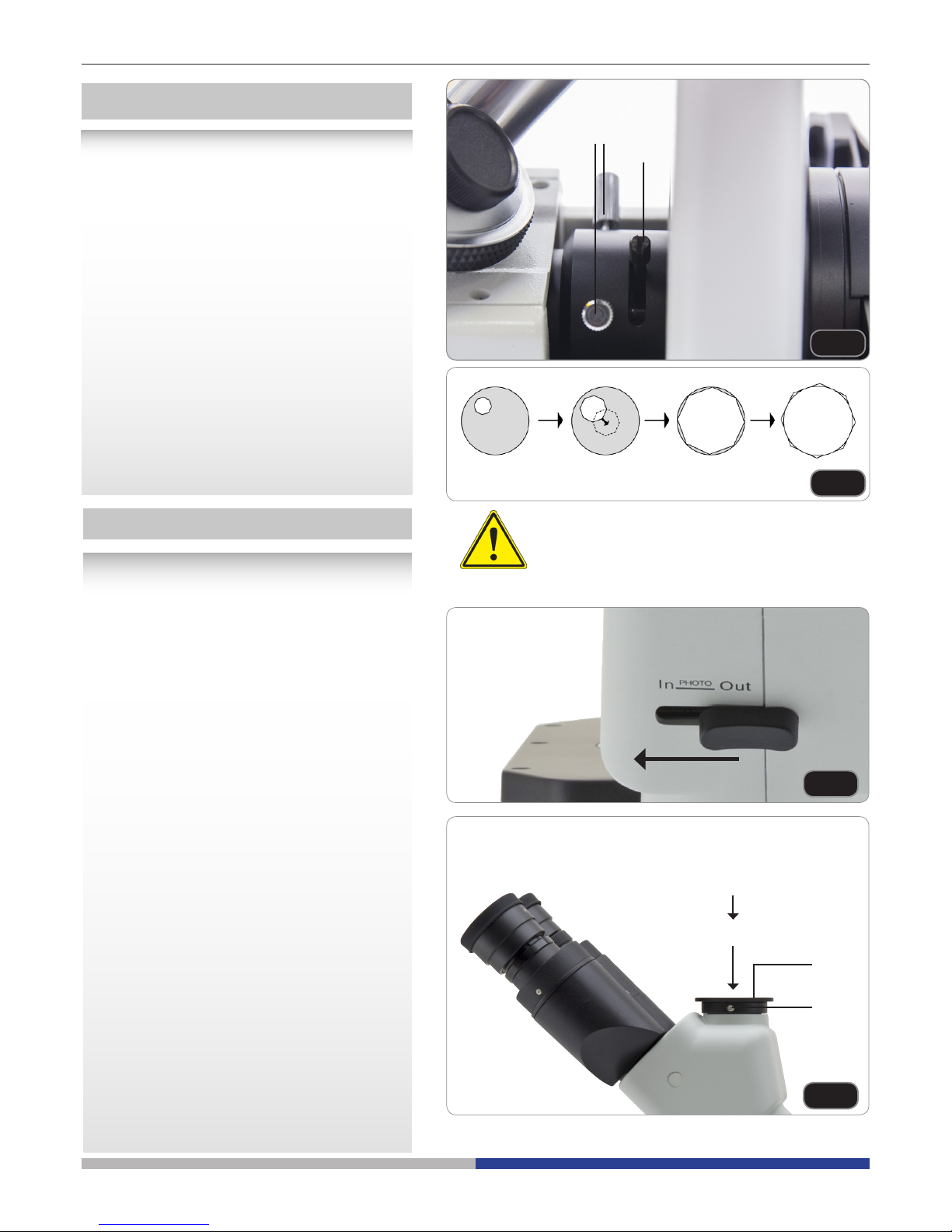
Página 62
Fig.46
Fig.47
Diafragma de campo
El diafragma de campo limita el diámetro de
luz que pasa a través de la muestra por lo
tanto elimina la luz sobrante de modo que se
concentra en un punto sobre la preparación lo
que mejora la calidad y contraste de imagen.
Girar el tornillo del diafragma de campo ① en
sentido horario de reloj para abrir el diafragma, y hacia el sentido contrario para cerrarlo
(Fig. 46)
Mover ambos tornillos ② ara centrar el
diafragma. (Fig. 46)
Abrir el diafragma de campo poco a poco, tal
como se muestra en la imagen (Fig.47), si
aparece de igual modo, signica que el diafragma de campo está centrado.
Para prevenir que se extinga la muestra no ex-
ponerla con la iluminación de epi-uorescencia
demasiado tiempo.
①
②
Fig.48
Fig.49
①
②
Instalación del adaptador para foto
1. Para activar la adquisición de video, tirar
la palanca de selección del recorrido
luminoso hacia el exterior. (Fig.48)
2. Destornillar el tornillo de bloqueo ① del
tubo trinocular y extraer el tapón antipolvo
②.
3. Instalar el adaptador para foto en el tubo
trinocular siguiendo las instrucciones,
después volver a atornillar el tornillo de
bloqueo ①.
4. Conectar el anillo de la cámara (si lo
posee) en el adaptador.
5. Conectar la cámara al anillo.
● Atención: en algunas cámaras
(principalmente cámaras réex) no se
suministra el anillo y por lo tanto, tendrá
que adquirirlo el usuario.
● Para fotograar preparaciones oscuras,
oscurecer los oculares y la mira con un
paño oscuro para limitar la luz difusa.
● Para medir los aumentos de la cámara
fotográca calcular los aumentos del
objetivo × cámara fotográca + aumentos
de la lente.
► Si se utiliza una cámara SLR, el
movimiento del espejo podría hacer
desplazar la cámara. Se aconseja elevar
el espejo, usar tiempos de exposición
largos y un alargador. (Fig.49)
MICROFOTOGRAFÍA
Cámara
Adaptador
Page 63
Página 63
Mantenimiento
Ambiente de trabajo
Se aconseja utilizar este microscopio en un ambiente limpio y seco; también se deben evitar los impactos. La
temperatura de trabajo recomendada es de 0-40°C y la humedad relativa máxima es de 85 % (en ausencia
de condensación). Si es necesario, utilizar un deshumidicador.
Consejos antes y después de la utilización del microscopio
• Durante los desplazamientos, mantener el microscopio en posición vertical y prestar
mucha atención para evitar que se caigan los accesorios móviles, por ejemplo, los oculares.
• Manejar con cuidado el microscopio evitando usar una fuerza mayor de la necesaria.
• Evitar reparar el microscopio por su cuenta.
• Apagar la luz inmediatamente después de haber utilizado el microscopio, cubrirlo con su
correspondiente funda antipolvo y mantenerlo en un ambiente limpio y seco.
Precauciones de seguridad relativas al sistema eléctrico
• Antes de conectar el microscopio a la toma de corriente, asegurarse que la tensión de
entrada del lugar donde se usa coincide con la tensión de utilización del microscopio y
que el interruptor del iluminador esté en la posición o.
• El usuario debe consultar las normas de seguridad de su país.
• El instrumento está dotado de una etiqueta de seguridad CE. No obstante estas pautas,
el usuario debería utilizar el microscopio en función de sus necesidades pero con un
mínimo de responsabilidad y seguridad.
Limpieza de la ópticas
• Si es necesario limpiar los componentes ópticos utilizar, en primer lugar, aire comprimido.
• Si no es suciente, limpiar las ópticas con un paño, que no esté deshilachado, humedecido en agua y
detergente neutro.
• Si todavía no es suciente, humedecer un paño con una mezcla de 3 partes de etanol y 7 partes de éter.
• Importante: el etanol y el éter son líquidos altamente inamables. No se deben utilizar cercanos a una
fuente de calor, chispas o instrumentación eléctrica. Utilizar en un ambiente bien aireado.
• No frotar la supercie de ningún componente óptico con la manos. Las huellas digitales pueden dañar las
ópticas.
• No desmontar los objetivos o los oculares para intentar limpiarlos.
Para obtener mejores resultados, utilice el kit de limpieza OPTIKA (véase el catálogo).
Si fuera necesario, enviar el microscopio a la empresa Optika para su mantenimiento se ruega utilizar el embalaje
original.
Page 64

Página 64
Résolution des problèmes
Revisar la información en la tabla a continuación para solucionar problemas de funcionamiento.
PROBLEMA CAUSA SOLUCION
I. Section Optique:
El iluminador está
encendido, pero el campo
visible está oscuro.
El enchufe del LED soporte no
está conectado al sistema de
iluminación
Conectar el LED soporte al sistema de
iluminación
La luminosidad es demasiado
baja
Regular la luminosidad
Se han superpuesto
demasiados ltros cromáticos
Reducir el número de ltros superpuestos
El borde del campo
visible se ha difuminado o
la luminosidad es asimétrica
El revólver portaobjetivos no
está en la posición correcta
Girar el revólver hasta que no se bloquee
con un click
El ltro cromático se ha introducido solo parcialmente
Introducir el ltro hasta el nal
El soporte para contraste de
fase no está en la posición
correcta
Desplazar el soporte hasta que no se
bloquee con un click
En el campo visible se ve polvo y
manchas
Hay polvo y/o manchas en la
preparación
Limpiar el preparado
Hay polvo y/o manchas en el
ocular
Limpiar el ocular
La imagen aparece doble El diafragma de apertura está
demasiado cerrado
Abrir el diafragma de apertura
La calidad de las imágenes
es insuciente:
La imagen no es nítida;
No hay un buen contraste;
Los detalles no son nítidos
El contraste e fase es
bajo.
El revólver no se sitúa en el
centro del recorrido luminoso
Girar el revólver hasta que no se bloquee
con un click
El diafragma de apertura en el
campo visible está demasiado
abierto o demasiado cerrado
Regular el diafragma de apertura
Las lentes (condensador,
objetivo, ocular y planchas de
cultivo) están sucias
Limpiar con cuidado todos los componentes ópticos
Para observaciones en con-
traste de fase, el espesor del
fondo de la muestra no debe
superar 1.2 mm.
Utilizar un portapreparados con un
espesor del fondo menor que 1,2mm
Utilizar un objetivo para observaciones en campo claro en
vez de uno para contraste de
fase
Cambiar el objetivo y usar uno para
contraste de fase
El anillo condensador no está
alineado con el anillo del objetivo de fase
Regular el anillo condensador hasta
obtener la alineación
El círculo luminoso y/o el anillo
de contraste de fase no está
centrado
Regular los tornillos hasta obtener el
centrado
El objetivo usado no es compatible con el anillo de fase
Utilizar un objetivo compatible
El contraste de fase depende
de la posición de la muestra
El portapreparados no es plano. Desplazar
la muestra hasta hallar la posición
correcta.
Page 65

Página 65
Un lado de la imagen
no está enfocado
El revólver no está en el centro
del recorrido luminoso
Girar el revólver hasta que no se bloquee
con un click
El preparado no está en la
posición correcta (ej. inclinado)
Situar el preparado horizontal al plano
La calidad óptica del cristal
portapreparados es baja
Utilizar un preparado de mayor calidad
II. Problemas mecánicos:
El mando macrométrico
gira con dicultad
El anillo de regulación de la
tensión está demasiado
cerrado
Aojar el anillo de regulación de la
tensión
El enfoque es inestable El anillo de regulación de la
tensión está demasiado ojo
Apretar el anillo de regulación de la
tensión
III. Problemas eléctricos:
El LED no se enciende El instrumento no tiene
alimentación
Vericar la conexión del cable de alimentación
La luminosidad es
insuciente
La luminosidad posee una baja
regulación
Adjust the brightness
La luz parpadea El cable de alimentación no
está conectado correctamente
Vericar la conexión del cable
IV. Montaje de los oculares:
El campo visible es diverso
en cada ojo
La distancia interpupilar no es
correcta
Regular la distancia interpupilar
La compensación dióptrica no
es correcta
Regular la compensación dióptrica
La técnica de observación no
es correcta y el usuario está
forzando la vista.
Cuando se mira en el objetivo, no jar
el preparado pero mirar todo el campo
visible. A intervalos regulares alejar los
ojos del objetivo y mirar desde lejos
para relajar la vista
V. Microfotografía y adquisición de videos
La imagen no está enfocada El enfoque no es correcto Regular el sistema de enfoque como
se explica en el presente manual
El borde de la imagen
no está enfocado
En un cierto grado esto es
innato a la naturaleza de los
objetivos acromáticos
Para reducir el problema al mínimo,
regular el diafragma de apertura en la
posición correcta
En la imagen aparecen
manchas claras
En el microscopio entra luz
difusa a través de los oculares
o a través de la mira de la cámara fotográca/telecámara
Cubrir los oculares y la mira con un
paño oscuro
Page 66
Página 66
Eliminación de residuos
En conformidad con el Art. 13 del D.L. de 25 julio 2005 n°151. Actuación de las Directivas 2002/95/CE, 2002/96/
CE y 2003/108/CE, relativas a la reducción del uso de sustancias peligrosas en la instrumentación eléctrica y
electrónica y a la eliminación de residuos.
El símbolo del contenedor que se muestra en la instrumentación o en su embalaje indica que el producto
cuando alcanzará el final de su vida útil se deberá recoger de forma separada del resto de residuos.
La gestión de la recogida selectiva de la presente instrumentación será llevada a cabo por el fabricante.
Por lo tanto, el usuario que desee eliminar la presente instrumentación tendrá que ponerse en contacto con el
fabricante y seguir el sistema que éste ha adoptado para permitir la recogida selectiva de la instrumentación.
La correcta recogida selectiva de la instrumentación para su posterior reciclaje, tratamiento y eliminación
compatible con el ambiente contribuye a evitar posibles efectos negativos al ambiente y a la salud y favorece
su reutilización y/o reciclado de los componentes de la instrumentación.
La eliminación del producto de forma abusiva por parte del usuario implicaría la aplicación de las sanciones
administrativas previstas en la normativa vigente.
Page 67

v 1.0 2017
Modèle
IM-3F
IM-3FL4
IM Series
MANUEL D’UTILISATION
Page 68

Page 68
Contenu
Avertissement
Symboles
Précautions
Usage
Description
Déballage
Assemblage
Opération
Maintenance
Réparation et entretien
Résolution des problèmes
Ramassage
Page 69

Page 69
Avertissement
Le présent microscope est un appareil scientique de précision créé pour orir une durrée de vie de plusieurs
années avec un niveau d’entretien mininum. Les meilleurs composants optiques et mécaniques ont été utilisés
pour sa conception ce qui fond de lui un appareil idéal pour une utilisation journalière.
Ce guide contient des informations importantes sur la sécurité et l’entretien du produit et par conséquent il doit
être accessible à tous ceux qui utilisent cet insrument.
Nous déclinons toute responsabilité quant à des utilisations de l’instrument non conformes au présent manuel.
Symboles
Le tableau suivant est un glossaire illustré des symboles qui sont utilisés dans ce manuel.
ATTENTION
Ce symbole indique un risque potentiel et vous avertit de procéder avec prudence.
CHOC ÉLECTRIQUE
Ce symbole indique un risque de choc électrique.
Précautions
Éviter choc électrique
Avant de connecter le câble d’alimentation au réseau électrique assurez vous que la tension d’entrée soit
compatible avec celle de l’appareil et que l’interrupteur de l’éclairage soit en position arrêt. L’utilisateur devra
consulter les normes de sécurités de son pays. L’appareil inclût une étiquette de sécurité C.E. Dans tous les cas,
l’utilisateur assume toute responsabilité relative à l’utilisation sûre de l’appareil. Suivre les directives ci-dessous
et lire ce manuel dans son intégralité pour un fonctionnement sûr de l’instrument.
Usage
Uniquement pour la recherche. Non destiné à usage thérapeutique ou diagnostique sur animaux ou êtres
humains.
Page 70

Page 70
Description
TUBE
D’OBSERVATION TRINOCULAIRE
(FIXE)
ANNEAU
D’AJUSTEMENT
DIOPTRIQUE
OCULAIRES
DISPOSITIF
CONTRASTE DE PHASE
(OPTIONAL POUR IM-3FL4)
ILLUMINATEUR
LED
CONDENSEUR
PORTE-FILTRE
MISE AU POINT
MACROMETRIQUE
MISE AU POINT
MICROMETRIQUE
ALIMENTATION
FLUORESCENCE
RÉGLAGE
TENSION
OBJECTIF
PLATINE
STATIF DU
MICROSCOPE
LEVIER DE
SÉLECTION
DE LUMIÈRE
PLATINE EN VERRE
Page 71

Page 71
Déballage
Le microscope est logé dans un récipient en polystyrène moulé.
Retirez la bande du bord du récipient et soulevez la moitié supérieure du récipient. Prenez soin d’éviter que les
objets optiques (objectifs et oculaires) tombent et se détériorent. En utilisant les deux mains (une autour du bras
et une autour de la base), soulevez le microscope du récipient et mettez-le sur un bureau stable.
Assemblage
Une fois que vous ouvrez la boîte, ce sont les composants du microscope:
① Statif du microscope
② Condenseur
③ Illuminateur LED
④ Alimentation uorescence
⑤ Câble d’alimentation
⑥ Porte-ltre
⑦ Insert en métal pour la platine
⑧ Insert en verre pour la platine
⑨ Objectifs
⑩ Oculaires
⑪ Filtres pour uorescence
⑫ Filtre fond Clair (IF550)
⑬ Écran orange
⑭ Ensemble de diaphragme
⑮ Port-lampe à mercure
①
②
⑪
⑫
⑬ ⑭
⑮
⑩
③
④
⑤
⑥
⑦ ⑧
⑨
Page 72

Page 72
③
Fig.2
Fig.3
Fig.4
Fig.5
Fig.1
①
②
1. Tournant le bouton de la mise au point ①
jusqu’à la plus basse position du revolver.
► Pour un transport sûr, le revolver est
placé dans la position la plus basse et
le bouton de commande de la tension
② est réglé à la tension appropriée à la
sortie d’usine du microscope. (Fig.1)
2. Visser l’objectif de grossissement le plus
faible sur la tourelle du côté juste, dans le
sens des aiguilles d’une montre. Monter
les autres objectifs de la même façon, selon l’ordre du plus faible au plus fort agrandissement.
► Note: les objectifs peuvent aussi être
installés à travers l’ouverture de la
platine. (Fig.2)
► Nettoyer régulièrement les objectifs. Dans
les microscopes inversés, les objectifs
sont très sensibles à la poussière.
► Recouvrir tous les trous inutilisés à l’aide
des bouchons pour une protection contre
la poussière et la contamination ③. (Fig.3)
► Pour la mise en fonctionnement, utiliser
l’objectif de grossissement faible (10X,
chercher à focaliser l’échantillon, passer
ensuite aux grossissements plus forts.
► En changeant l’objectif, tourner lentement
le revolver jusqu’à ce qu’il fasse un déclic.
Ce qui signie que l’objectif est dans la
position juste, au centre du parcours de la
lumière.
Installation des objectifs
L’extension de platine peut être installée
de chaque côté de la platine pour élargir la
surface de travail. La platine mécanique doit
être installée sur le côté opposé de l’extension.
Pour les opérateurs droitiers, la platine
mécanique est installée normalement sur le
côté droit.
1. Installation de l’extension de la platine
d’abord, visser les verrous sur l’extension,
monter ensuite l’extension en dessous de
la platine (Fig.4)
2. Installation de la platine mécanique:
comme pour l’extension, la platine
mécanique est xée par deux vis sous de
la platine. (Fig.5)
Installation de l’extension de la platine
et de la platine mécanique (OPTIONNEL
)
Page 73

Page 73
Fig.6
Fig.7
Fig.8
Fig.9
Fig.10
1. En utilisant la plate-forme en verre
s’assurer que l’insert est horizontale
2. Installer la plate-forme dans l’ouverture de
la platine. (Fig.6)
Installation de la platine d’insertion
Installation des oculaires
Enlever le bouchon des tubes oculaire, Insérer
les oculaires dans les tubes. (Fig.7)
1. Insérer l’unité d’illumination du condenseur
dans le support. (Fig.8)
2. Tourner l’unité d’illumination du condensateur dans le sens des aiguilles d’une
montre à environ 90 °, la marque “ AS” du
porte-ltres faisant face (3) continuer, en
alignant la vis de l’unité d’illumination du
condenseur et le trou du support, visser
ensuite le verrou dans le trou avec la allen
tra clé e de de serrage fournie.(Fig.9)
3. Insérer la prise de courant de connexion
dans le cric de connexion.
4. Placer le logement LED doucement dans
l’unité d’illumination. (Fig.10)
Installation du condenseur
L’unité d’éclairage et la LED
logement
Page 74
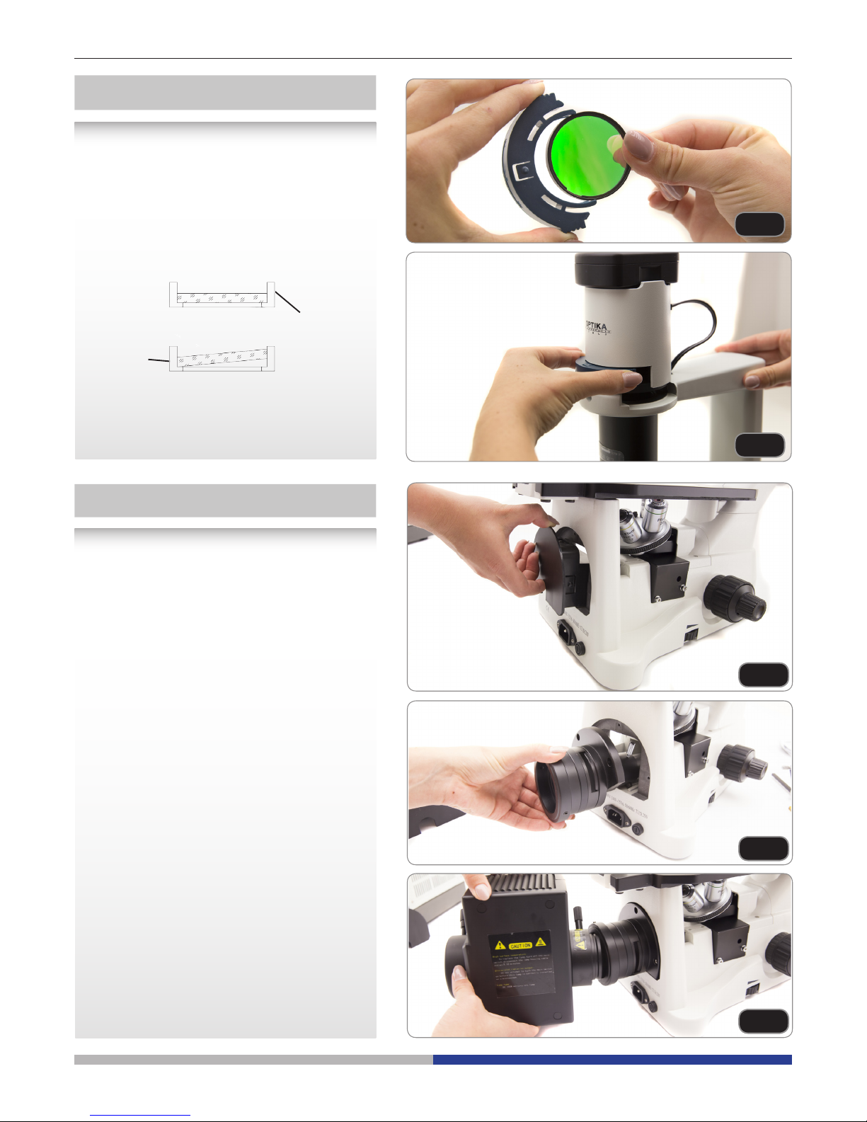
Page 74
• Tirez le couvercle en plastique noir, à partir de l’arrière du microscope. (Fig.13)
• Insérez l’ensemble lentille/diaphragme à
l’arrière. Pour faciliter l’insertion, il sut
d’incliner l’ensemble à environ 45 ° et de
le déplacer vers l’avant. Fixez-le à l’aide
des 3 vis allen fournies. (Fig.14)
• Insérez le porte-llampe et xez-le avec la
vis Allen (déjà à l’intérieur du tube de suppor (1) ). (Fig.15)
Installer la uorescence
Fig.11
Fig.12
Fig.13
Fig.14
Fig.15
► Enlever le porte-ltres, ensuite installer
les ltres en couleur que vous désirez.
(Fig.11, Fig.12)
Monter les supports plats du ltre en
couleur comme illustré dans ①, en
vériant qu’ils ne sont pas inclinés.
► Si le ltre en couleur est incliné ou pla-
cé autrement, ② les ltres de couleur
peuvent tomber.
Les ltres de couleur peuvent être empilés
dans le support. Cela permet d’installer
autant de ltres désirés, dans la mesure
où l’épaisseur entière est inférieure à 11
millimètres.
Installation des ltres en couleur
①
②
Page 75

Page 75
• Insérez le support de ltre dans son emplacement près du porte-lampe. (Fig.16)
• Dévissez le couvercle de protection sur le
côté gauche du microscope, avec la clé allen fournie. (Fig.17)
• Faites glisser le ltre vert à l’intérieur du
guide en queue d’aronde, après avoir vissé le levier du ltre dans le trou leté du
ltre. Remonter le couvercle de protection
dans sa position. (Fig.18)
• Sur le levier du ltre, vissez la borne avec
la gravure G. Répétez les mêmes étapes
pour le côté droit, en montant le ltre bleu.
(Fig.19)
• Pour éviter les dommages éventuels contre le rayonnement UV, monter l’écran de
protection orange comme illustré. (Fig.20)
Fig.16
Fig.17
Fig.18
Fig.19
Fig.20
Page 76

Page 76
• Branchez le câble de l’alimentation ex-
terne à la lampe HBO. (Fig.21; Fig.22)
• Branchez le câble d’alimentation à
l’alimentation externe. (Fig.23)
Fig.21
Fig.22
Fig.23
• La tension d’entrée pour l’alimentation en uorescence est de 110 à 240 Vca.
• Veuillez utiliser le câble d’alimentation fourni par notre société. Choisissez celui qui vous con-
vient s’il est manquant ou endommagé.
• Branchez l’alimentation correctement, assurez-vous d’avoir une bonne connexion.
Page 77

Page 77
Fig.24
Fig.25
Fig.26
Monter ou remplacer la lampe à
mercure
Avant de remplacer l’ampoule, réglez la puissance de la uorescence en débranchant le
câble d’alimentation. Assurez-vous que la
lampe est complètement refroidie.
Desserrer complètement la vis de blocage
① (Fig.24) et enlever le porte-ampoule ②.
Desserrer la vis de blocage ③ et enlever le
mât en plastique ④. (Fig.25)
La lampe HBO a 2 pôles de diérentes dimensions, de sorte qu’elle ne s’insère que dans
une direction: insérez le pôle d’anode (plus
grand) dans le support xe ① et l’autre pôle
dans le support exible. Puis serrez la vis.
(Fig.26)
Replacez la porte de la lampe en place et
serrez la vis de blocage de la porte.
②
③
④
①
①
Page 78
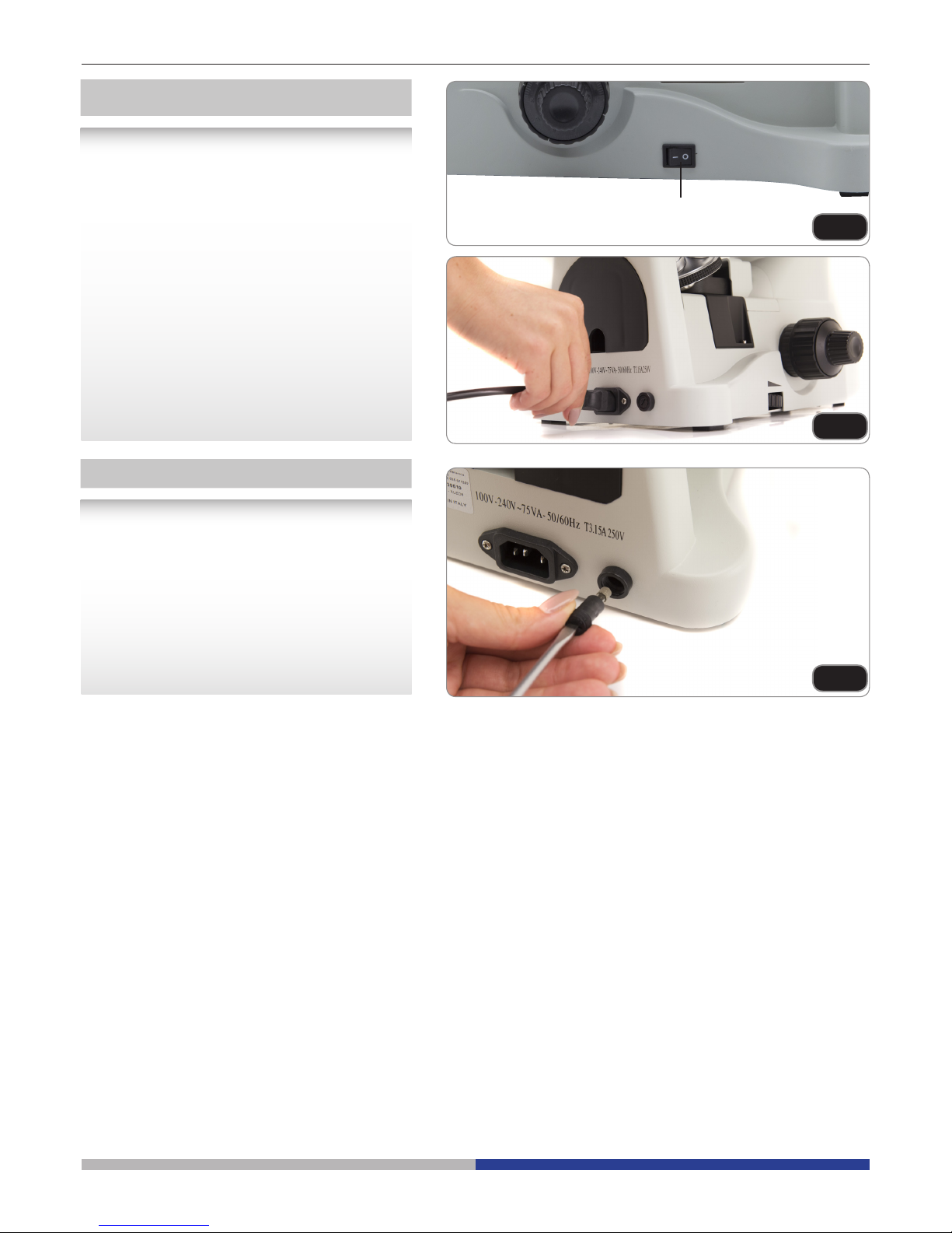
Page 78
Fig.27
Fig.28
Fig.29
①
1. Placer l’interrupteur principal ① sur “O”
avant de brancher le câble d’alimentions.
(Fig.27)
2. Insérer le câble dans la pris de courant du
microscope. (Fig.28)
3. Brancher le câble d’alimentation sur la
douille d’alimentation principale. Vérier
pour une connexion sûre.
► Utiliser s’il vous plaît le câble
d’alimentation fourni. S’adresser
au service compétent lorsqu’il est
endommagé ou perdu.
► Brancher le câble d’alimentation à
une source d’alimentation électrique
(à terre) seulement.
Placer l’interrupteur principal sur “O” avant de
remplacer le fusible et débrancher le câble
d’alimentation.
Faire tourner le support du fusible utilisant un
tournevis droit. Insérer un nouveau fusible dans
le support, replacer le support à l’intérieur du
dispositif. (Fig.29)
► Voir la partie postérieure du microscope
pour les valeurs du fusible.
Branchement du câble d’alimentation
Remplacement du fusible
Page 79
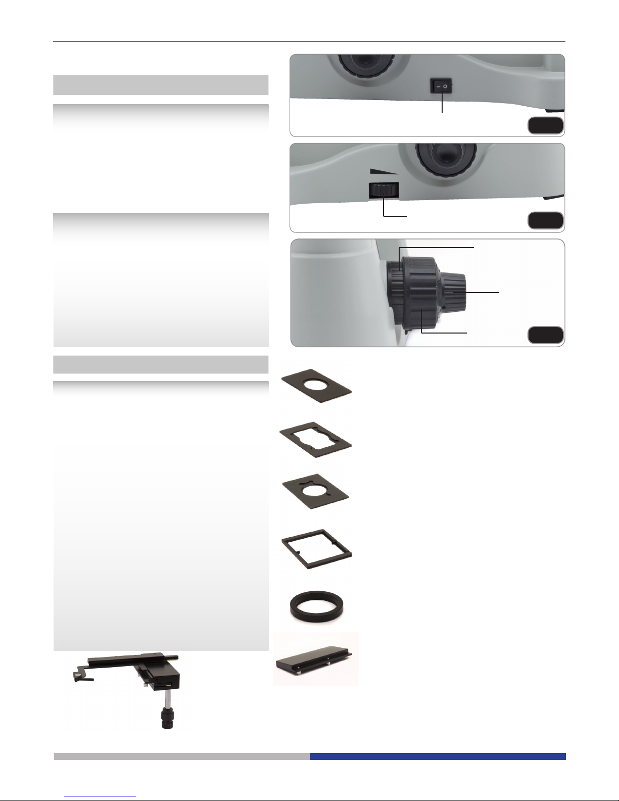
Page 79
Fig.30
Fig.31
①
②
①
②
③
Fig.32
Mise sous tension de la LED
Brancher le câble, mettre en fonctionnement
l’intérrupteur principal ①. (Fig.30)
Réglage éclairage
Tourner le bouton de commande de l’éclairage
② pour augmenter et abaisser l’éclairage.
(Fig.31)
Réglage de la Tension
► Le bouton de réglage ① est déjà placé
à une tension adaptée à la sortie
d’usine.
Si le revolver descend tout seul, ou l’échantillon
n’est plus focalisé au moment de régler la mise
au point ne ③, alors le bouton de mise au
point macroscopique est trop desserré. Tourner le col du bouton de commande de la tension
② serrer la commande macrométrique ①.
serrer la commande macrométrique (Fig.32)
Mise en place des échantillons
► Pour la meilleure qualité d’image,
utiliser des bouteilles, des capsules de
Petri et des lames d’une épaisseur de
1.2 millimètres.
1. Placez l’insert approprié pour votre
spécimen (selon la gure de droite) sur
la platine et xez-le avec les valewts de
xation de la platine.
2. Utilisant les commandes X et Y, placer
l’échantillon à la position désirée. (Axes
de Mouvement: 120 (la largeur) × 78 (la
Longueur) mm).
Déplacement de l’échantillon
Placer l’échantillon dans la position désirée
utilisant les mains ou les boutons de commande
de la platine mécanique
► En changeant les objectifs, faites
attention de ne pas toucher les plaques
d’adaptation avec les objectifs, car
leur poids peut endommager la lentille
frontalement.
INSTALLATION INITIALE
PLATINE (OPTIONNEL)
Opération
M-793.1
Support pour Petri diamètre 38mm (M-793.2 nécessaire)
M-793.2
Support pour Terasaki et Petri diamètre 65mm.
M-793.3
Support pour lame et Petri diamètre 54mm.
M-793.4
Support pour 2+2 lames.
M-793.6
Support pour Chambre d’Utermöhl (M-793.3 nécessaire).
M-792
Platine mécanique pour IM-3.
M-793.7
Extension latéral pour série IM-3.
Page 80

Page 80
②
Fig.33
Fig.34
Fig.35
③
①
Ajustement dioptrique
1. Observer à travers l’oculaire juste avec
votre oeil droit et focaliser l’échantillon.
2. Observer à travers l’oculaire gauche
avec seulement votre oeil gauche. Si
l’image n’est pas nette, utiliser l’anneau
de réglage dioptrique ① pour compenser.
(Fig.33)
► La valeur d’ajustement est ±5 diop-
trie. Le nombre indiqué sur l’anneau
d’ajustement devrait correspondre à la
correction dioptrique de l’opérateur.
Réglage de la distance interpupillaire
En observant avec les yeux, tenir les deux
assemblages de prisme d’oculaire. Les faire
tourner autour de leur
axe commun jusqu’à ce que les champs de
vision coïncident.
► La graduation sur l’indicateur de dis-
tance interpupillaire ②, montrée par le
point “.” sur le support de l’oculaire,
montre la distance entre les yeux de
l’opérateur. (Fig.34)
La valeur de la distance interpupillaire est 4875 millimètres.
Sélection parcours lumineux
Tirer le levier sélectionneur du parcours de
l’éclairage ③ latéralement utilisant votre
pouce, en choisissant le parcours d’éclairage
dont vous avez besoin. (Fig.35
TUBE D’OBSERVATION
LEVIER SÉLECTIONNEUR
PARCOURS ÉCLAIRAGE
ÉCLAIRAGE APPLICATION
In 20% utilisé pour observation
binoculaire, et 80% pour vidéo ou
photographie
Observation binoculaire, télévision,
et micrographie ou vidéo
peuvent être utilisées simultanément
Out 100% utilisé pour observation
binoculaire
Observation binoculaire
Page 81

Page 81
Fig.36
Fig.38
Fig.39
Fig.37
70-
30-
70-80%
30-20%
①
①
②
②
③
Usage des ltres en couleur
Le choix de la couleur appropriée selon votre
besoin. (Fig.36)
Vous pouvez empiler un groupe de ltres en
couleur dans le porte-ltres, s’assurant qu’ils
sont de niveau et d’épaisseur entièrement
inférieurs à 11 millimètres.
Utilisation de l’ouverture du diaphragme
Observant en champ clair, le diaphragme
d’ouverture contrôle l’ouverture numérique du
système d’illumination. Lorsque l’ouverture
numérique de l’objectif et de l’ouverture
du système d’illumination sont alignées, la
résolution la plus importante est obtenue.
L’ouverture peut être changée en déplaçant le
levier d’ajustement d’ouverture ① Est l’image
du diaphragme d’ouverture, ② Est le bord de
l’objectif. Généralement, lors de l’observation
d’un échantillon entièrement chromatique,
vous devez dénir la taille du condenseur à
70-80% de l’ouverture de l’objectif.
Lors de l’observation d’échantillons non colorés
(par exemple des bactéries), commencez à
partir de 70% et tournez lentement le levier
diaphragme d’ouverture dans le sens horaire..
(Fig.37)
UNITE D’ILLUMINATION
Coulisseau pour contraste de phase
Ajustement du dispositif de phase.
● L’anneau clair est pré-centré quand le microscope sort d’usine. Il ne devrait donc y
avoir aucun autre besoin de réglage. Si le
recentrage est nécessaire, il peut être
exécuté à l’aide des deux commandes
sur les deux côtés.
● L’anneau lumineux 4x/10x ① doit être
utilisé avec les objectifs à contraste de
phase 4x et 10x , l’anneau lumineux 20x /
40x ② vec les 20x et 40x et l’ouverture ③
est utilisée pour le fond clair. (Fig.38)
Installation du dispositif de contraste de phase
1. Insérer le dispositif dans le système d’illu-
mination, la partie imprimée faisant face.
2. Lacer le dispositif dans la position désirée,
arrêt par claquement.
3. En observation de contraste de phase,
conserver le levier de réglage d’ouverture
du diaphragme sur la position “O” (ouverte). (Fig.39)
CONTRASTE DE PHASE
(
OPTIONAL POUR IM-3FL4
)
FILTRE
COULEUR
USAGE
Green Seul ltre en couleur de contraste (vert) (uti-
lisé pour contraste de phase en microscopie)
Page 82

Page 82
Fig.40
Fig.41
Fig.42
①
②
Centrage de l’anneau
► D’habitude cette opération n’est pas
nécessaire. En cas de nécéssité,
éectuer les opérations suivantes:
1. Placer un échantillon sur la platine et
focaliser.
2. Enlever l’oculaire du tube sans le réglage
dioptrique et le remplacer par le télescope
de centrage (CT). (Fig.40)
3. Vérier que l’anneau de phase et l’objectif
correspondent et que tous les deux sont
fermement mis sur l’ arrêt de claquement.
4. Utiliser le CT pour focaliser l’image de
l’anneau clair ① et l’image de l’anneau
de contraste de phase ②. Si l’image de
l’anneau lumineux n’est pas nette, agir
sur l’oculaire du CT jusqu’à ce que vous
puissiez voir une image claire de l’anneau
lumineux.
5. Utiliser les commandes des deux trous
de centrage du dispositif de contraste de
phase utilisant un tournevis jusqu’à ce
que le centre de l’anneau lumineux et le
centre de l’anneau de contraste de phase
coïncident.
6. Les objectifs de contraste de phase 10X et
20X utilisent le même anneau sur le dispositif
de contraste de phase. La coïncidence du
centre de l’anneau lumineux et du centre
de contraste de phase doit être
vériée avec les deux objectifs.
(Fig.41; Fig.42)
► Si l’anneau clair est centré
incorrectement, le contraste sera
sévèrement diminué.
► L’anneau de phase peut avoir besoin d’
un nouveau centrage durant et après
l’observation.
► L’anneau de phase pourrait montrer un
mauvais alignement apparent lorsque le
couvercle de verre n’est pas plat.
Page 83

Page 83
Fig.45
Fig.43
Fig.44
Centrage de l’ampoule au mercure
Après avoir allumé l’alimentation en
uorescence, laisser la lampe HBO,
atteindre la stabilité thermique (au moins 5
minutes) avant de procéder à l’alignement.
Tournez le revolver à une position vide sans
objectif, et placez un morceau de papier blanc
directement sur le trou. (Fig.43)
Tirez sur le levier de sélection du ltre jusqu’à
ce que le ltre bleu soit inséré dans le trajet
lumineux.
Ouvrez complètement le diaphragme de
champ. (Fig.44) Réglez la commande de mise
au point de la lampe ①, la vis de réglage
verticale ②, la vis de réglage horizontale ③
an d’obtenir une image de l’ampoule sur le
papier blanc, comme sur la Fig.45 Ⓐ.
(Fig.44 Régler la vis de focalisation ④ pour
le miroir rétro-rééchissant, la vis de centrage
horizontale ⑤, la vis de centrage verticale
⑥, pour obtenir une image de la réexion de
l’ampoule sur le papier blanc, similaire à la
Fig.45 Ⓑ.
(Fig.44) Continuer à ajuster les vis du miroir
rétro-rééchissant jusqu’à obtention d’une
image symétrique de l’ampoule et de sa
réexion, toutes deux très proches du centre
du trajet lumineux Fig. 45 Ⓒ.
①
Ⓐ Ⓑ Ⓒ
②
③
④
⑤
⑥
Page 84

Page 84
Fig.46
Fig.47
Diaphragme de champ visuel
Le diaphragme de champ limite le diamètre du
faisceau lumineux sur le plan de l’échantillon,
éliminant ainsi la lumière parasite an d’améliorer le contraste de l’image. Lorsque l’image
du diaphragme de champ est juste au bord du
champ de vision, le système peut fournir la
meilleure performance.
Tournez le levier de réglage ① du diaphragme
de champ dans le sens des aiguilles d’une
montre pour ouvrir le diaphragme, sinon pour
le fermer. (Fig. 46)
Réglez les vis ② des deux côtés du
diaphragme de champ pour centrer l’image du
diaphragme lui-même. (Fig. 46)
Ouvrez le diaphragme de champ progressivement, si l’image du diaphragme de champ est
juste inscrite au champ de vue, cela signie
que le diaphragme de champ a été centré.
(Fig.47)
An d’éviter l’extinction de l’échantillon par
uorescence, ne pas exposer trop longtemps
la même partie de l’échantillon.
①
②
Fig.48
Fig.49
①
②
Installation de l’adaptateur de photographie
1. Pour activer la porte-vidéo, retirer le levier
de sélection du parcours lumineux en
position ‘IN’. (Fig.48)
2. Desserrer la butée de verrouillage ① sur
le tube d’observation trinoculaire et enlever le bouchon antipoussières ②.
3. Insérer l’anneau de l’appareil photographique (de chacun) dans l’adaptateur. ①.
4. Fixez l’anneau de la caméra (le cas
échéant) à l’adaptateur.
5. Placer l’appareil photo sur l’adaptateur.
● Attention: pour certains appareils photographiques (principalement Reex), l’anneau n’est pas fourni avec le microscope,
l’opérateur doit s’en procurer.
● Pour la photographie d’échantillons obscurs, couvrir les oculaires et le viseur avec
un tissu sombre pour réduire la lumière
diuse.
● Le grossissement de l’appareil peut être
calculé par: le grossissement objectif x
appareil + grossissement de lentille.
► En prenant des photos avec un SLR, le
mouvement du miroir peut provoquer
un mouvement de l’appareil. Soule-
ver le miroir s’il vous plaît, utiliser des
temps d’exposition longs et utilisez un
cordon d’extension. (Fig.49)
MICROPHOTOGRAPHIE
Caméra
Adaptateur
Page 85

Page 85
Réparation et entretien
Environnement de travail
Il est conseillé d’utiliser le microscope dans un environnement propre et sec, protégé des impactes, à une
température comprise entre 0°C y 40°C et avec une humidité relative maximale de 85% (en absence de
condensation). Il est conseillé d’utiliser un déshumidicateur si nécessaire.
Conseils avant et après l’utilisation du microscope
• Maintenir le microscope toujours en position verticale lorsque vous le déplacez.
• Assurez vous que les pièces mobiles (oculaires) ne tombent pas.
• Manipulez avec attention le microscope en évitant de le forcer.
• Ne réparez pas le microscope vous même.
• Éteindre immédiatement la lumière après avoir utilisé le microscope, couvrez le avec la
housse prévue à cet eet et conservez le dans un endroit propre et sec.
Précaution de sécurité sur le système électrique
• Avant de connecter le câble d’alimentation sur le réseau électrique assurez vous que la
tension d’entrée soit compatible avec celle de l’appareil et que l’interrupteur de l’éclai-
rage soit en position arrêt.
• L’utilisateur devra consulter les normes de sécurités de son pays.
• L’appareil inclût une étiquette de sécurité C.E. Dans tous les cas, l’utilisateur assume
toute responsabilité relative à l’utilisation sûre de l’appareil.
Nettoyage des optiques
• Si vous souhaitez nettoyer les optiques, utilisez dans un premier temps de l’air comprimé.
• Si cela n’est pas susant, utilisez alors un chion non eloché, humidié avec un peu d’eau et avec un
détergent délicat.
• Comme dernière option, il est possible d’utiliser un chion humide avec une solution de 3:7 d’éthanol et
d’éther.
• Attention: l’éthanol et l’éther sont des substances hautement inammables. Ne les utilisez pas près d’une
source de chaleur, d’étincelles ou d’appareils électriques. Les substances chimiques doivent être utilisées
dans un environnement aéré.
• Ne pas frotter la supercie d’aucun des composants optiques avec les mains.
• Les empreintes digitales peuvent endommager les parties optiques.
Pour les meilleurs résultats, utiliser le kit de nettoyage OPTIKA (voir le catalogue).
Conserver l’emballage d’origine dans le cas où il serait nécessaire de retourner le microscope au fournisseur pour
un entretien ou une réparation.
Page 86

Page 86
Résolution des problèmes
Passer en revue les informations dans le tableau ci-dessous pour résoudre les problèmes opérationnels.
PROBLEME RAISON
SOLUTION
I. Section Optique:
The illumination is open, but the eld
of view is dark.
La prise de courant de la
douille n’est pas branchée au
jeu d’illumination
Les Brancher
L’éclairage est très faible Adjuster le réglage
Trop de ltres couleurs ont été
empilés
Minimiser le nombre des ltres
2. Le bord du champ vu en vignette
ou l’éclairage est asymétrique.
Le Revolver n’est pas dans la
position correcte
Tourner le Revolver jusqu’à l’arrêt de
claquement
Le ltre en couleur est
partiellement inséré
Insérer le ltre jusqu’à la profondeur
complète
Le Dispositif contraste de
phase n’est pas dans la
position exacte
Placer le Dispositif à l’arrêt de claquement
3. La poussière et les taches peuvent
être vues dans le champ visuel.
Il y a des taches et de la
poussière sur l’échantillon
Nettoyer l’échantillon
Il y a des taches et de la
poussière sur l’oculaire
Nettoyer l’oculaire
4. Il y a une image double apparente. L’ouverture du diaphragme est
trop petite
Ouvrir le diaphragme d’ouverture
5. Qualité image pauvre:
L’ image n’est pas nette Le contraste
n’est pas élévé
Les détails ne sont pas clairs
Le contrast de phase est bas
Le Revolver n’est pas au centre
du parcours lumineux
Tourner le Revolver jusqu’à un arrêt de
claquement
Le diaphragme d’ouverture
montre que l’ ouverture du
champ visuel est trop grande
ou trop petite
Ajuster le diaphragme d’ouverture
Les lentilles (le condensateur,
l’objectif, les oculaires sont
moisis) sont sales
Nettoyer tout le système optique
Observation en contraste de
phase, l’épaisseur inférieur de
l’échantillon est plus de 1.2 mm
Utiliser support-préparations dont
l’épaisseur inférieur est
moins de 1.2mm
Un objectif pour champ clair
utilisé pour observation en
contraste de phase
Changer par un objectif de contraste phase
L’anneau du condenseur n’est
pas aligné à l’anneau de phase
de l’objectif
Ajuster l’anneau du condenseur sur
l’anneau de phase de l’objectif
L’anneau lumineux et/ou
l’anneau de contraste de phase
n’est pas centré
Utiliser les butées pour centrage
L’objectif utilisé n’est pas
compatible avec l’anneau de
phase
Utiliser un objectif compatible s’il vous plaît
Le contraste de phase dépend
de la position de l’échantillon
Le support-préparations n’est pas plat.
Placer l’échantillon sur la surface trouvée
jugée compatible.
Page 87

Page 87
6. Un côté de l’image est ou. Le revolver n’est au centre du
parcours lumineux
Tourner le revolver à un arrêt de
claquement
L’échantillon est déplacé
(incliné)
Place l’échantillon plat sur la platine
La performance optique
du verre de couverture de
l’échantillon est pauvre
Utiliser un verre de couverture de meilleure
qualité
II. Section Mécanique
1. Commande
macrométrique dur à tourner.
Le col de réglage de la tension
est trop serré
Desserrer le col de réglage de la tension
2. Mise au point instable Le col de réglage de la tension
est trop desserré
Serrer le col de réglage de la tension
III. Section Électrique
1. Il LED La lampe
n’allumera pas
Pas d’ alimentation électrique Vérier la connexion du câble
d’alimentation
2. L’éclairage n’est pas assez. L’intensité lumineuse est faible Adjuster l’éclairage
3. Eclairs de lumière. Connexion incorrecte du câble Contrôler câble d’alimentation
IV. Montage tube d’observation
Champ visuel diérent d’un oeil à
l’autre.
Distance interpupillaire
incorrecte
Réglage distance interpupillaire
Correction dioptrique incorrecte Réglage correction dioptrique
Observation technique
incorrecte, éorts visuels de
l’opérateur
Observation à travers l’ objectif, ne pas
xer l’échantillon mais observer tout le
champ visuel. De temps en temps éloigner
les yeux, regarder un objet distant, et
retourner à l’objectif
V. Microphotographie et vidéo:
1. L’image est oue. Mise au point incorrecte Réglage mise au point comme illustré dans
ce présent manuel
2. Les bords de l’image sont ous Relatif en substance à la
nature des objectifs
achromatiques généralement
Minimiser le problème par un réglage
correcte du diaphragme d’ouverture
3. Rais lumineux sur l’image. Entrée de lumière diuse
dans le microscope à travers
les oculaires et le viseur de la
caméra
Couvrir les oculaires et le viseur avec un
pan de tissu obscur
Page 88

Page 88
Ramassage
Conformément à l’Article 13 du D.L du 25 Juillet 2005 nº151
Action des Directives 2002/95/CE, 2002/96/CE et 2003/108/CE, relatives à la réduction de l’utilisation de
substances dangereuses dans l’appareil électrique et électronique et à l’élimination des résidus.
Le Symbole du conteneur qui figure sur l’appareil électrique ou sur son emballage indique que le produit devra
être, à la fin de sa vie utile, séparé du reste des résidus. La gestion du ramassage sélectif du présent instrument
sera effectuée par le fabricant. Par conséquent, l’utilisateur qui souhaite éliminer l’appareil devra se mettre en
contact avec le fabricant et suivre le système que celui-ci a adopté pour permettre le ramassage sélectif de
l’appareil. Le ramassage sélectif correct de l’appareil pour son recyclage, traitement et élimination compatible
avec l’environnement contribue à éviter d’éventuels effets négatifs sur l’environnement et la santé et favorise
sa réutilisation et/ou recyclage des composants de l’appareil. L’élimination du produit de manière abusive de la
part de l’utilisateur entraînera l’application de sanctions administratives sur la norme en vigueur.
Page 89

v 1.0 2017
Model
IM-3F
IM-3FL4
IM Series
BEDIENUNGSANLEITUNG
Page 90

Pagina 90
Inhaltsverzeichnis
Warnung
Zeichen
Sicherheitshinweise
Verwendungsempfehlungen
Beschreibung
Önung der Verpackung
Zusammenbau
Bedienungsanleitung
Wartung
Störungssuche
Wiederverwertung
Page 91
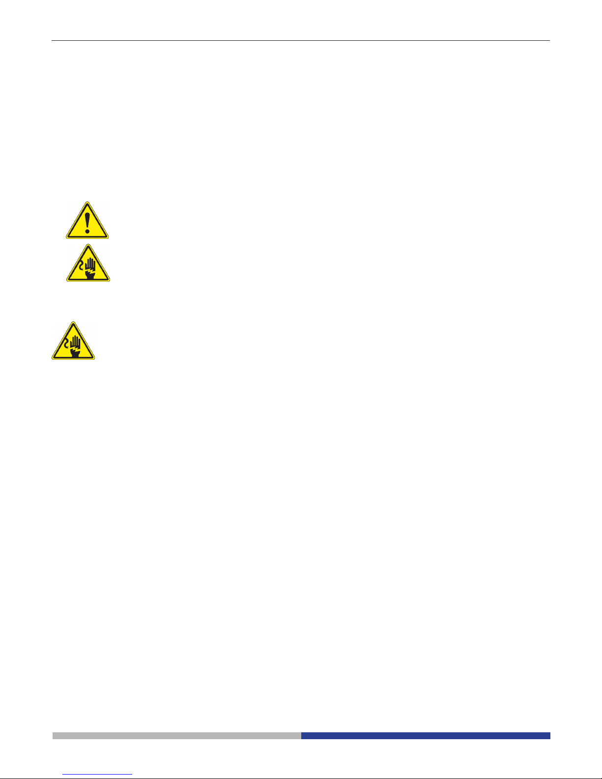
Pagina 91
Warnung
Dieses Mikroskop ist ein wissenschaftliches Präzisionsgerät, es wurde entwickelt für eine jahrelange Verwendung bei einer minimalen Wartung. Dieses Gerät wurde nach den höchsten optischen und mechanischen
Standards und zum täglichen Gebrauch hergestellt. Diese Bedienungsanleitung enthält wichtige Informationen
zur korrekten und sicheren Benutzung des Geräts. Diese Anleitung soll allen Benutzern zur Verfügung stehen.
Wir lehnen jede Verantwortung für eine fehlerhafte, in dieser Bedienungsanleitung nicht gezeigten Verwendung Ihrer Produkte ab.
Zeichen
Die folgende Tabelle zeigt die Symbole, die in dieser Anleitung verwendet werden.
ACHTUNG
Dieses Symbol zeigt eine potentielle Gefahr und warnt, mit Vorsicht zu verfahren.
STROMSCHLAG
Dieses Symbol weist auf eine Gefahr von Stromschlägen.
Sicherheitshinweise
Elektrische Vorsichtsmaßnahmen
Bevor Sie das Netzkabel anstecken, vergewissern Sie sich, dass die Spannung für das Mikroskop geeignet ist
und dass der Beleuchtungsschalter sich in Position OFF bendet.
Beachten Sie alle Sicherheitsvorschriften des Arbeitsplatzes, an dem Sie mit dem Mikroskop arbeiten. Das
Gerät entspricht den CE-Normen. Die Benutzer tragen während der Nutzung des Geräts die volle Verantwortung
dafür.
Verwendungsempfehlungen
Nur für Forschung. Nicht für therapeutische Verwendung.
Page 92

Pagina 92
Beschreibung
TRINOKULARAUSGANGSTUBUS
DIOPTRIENVERSTELLUNGSRING
OKULARE
LED
GEHÄUSE
KONDENSOR
FILTERTRÄGER
FÜR FARBFILTER
FEINTRIEBKNOPF
GROBTRIEBKNOPF
FLUORESZENZ
NETZTEIL
SPANNUNGSEINSTELLUNGSRING
OBJEKTIVE
TISCH
MIKROSKOPKÖRPER
LICHTWEGAUSWAHL
GLASSTUFEN
EINFÜGEN
SLIDER FÜR
PHASENKONTRAST
(OPTIONAL FÜR IM-3FL4)
Page 93

Pagina 93
① Mikroskop-Körper
② Kondensor
③ LED-Leuchte
④ Fluorescence power supply
⑤ Stromkabel
⑥ Filterhalter
⑦ Metall-Einsatz für Objekttisch
⑧ Glas-Einsatz für Objekttisch
⑨ Objektive
⑩ Okulare
⑪ Fluoreszenzlter
⑫ Hellfeld-Filter IF550
⑬ Orange Schirm
⑭ Blende-Baugruppe
⑮ Quecksilberlampgehäuse
①
②
⑪
⑫
⑬ ⑭
⑮
⑩
③
④
⑤
⑥
⑦ ⑧
⑨
Önung der Verpackung
Das Mikroskop ist in einem geformten Schaumpolystyrol Verpackung verpackt. Entfernen Sie das Klebeband
von der Verpackung und ziehen Sie die obere Hälfte der Verpackung hoch. Beachten Sie bitte, die optischen Bestandteile (Objektive und Okulare) nicht fallen zu lassen oder nicht zu beschädigen. Ziehen Sie das Mikroskop
aus der Verpackung mit beiden Händen (eine um den Arm und eine um die Basis) heraus und legen Sie es auf
eine stabile Oberäche.
Zusammenbau
Beim önen der Schachtel, nden Sie die folgenden Mikroskop-Komponenten:
Page 94

Pagina 94
③
Fig.2
Fig.3
Fig.4
Fig.5
Fig.1
①
②
1. Drehen Sie den Grobtriebknopf ① bis der
Revolver sich in die tiefste Position bendet.
► Aus Sicherheitsgründen wird der Re-
volver vor dem Versand in die tiefste
Position gesetzt und der Spannungsring ② wird zur richtigen Spannung
eingestellt. (Fig.1)
2. Befestigen Sie das Objektiv mit der kleinsten Vergrößerung auf die rechte Seite des
Revolvers, dann drehen Sie den Revolver
im Uhrzeigersinn. Montieren Sie die anderen Objektive auf die gleiche Weise, vom
Objektiv mit der kleinsten Vergrößerung zu
dem mit der höchsten.
► Hinweis: man kann die Objektive auch
durch die Kreuztischönung montieren. (Fig.2)
► Behalten Sie die Objektive sauber. In den
Inversmikroskopen sind die Objektive sehr
staubempndlich.
► Um Staub und Kontaminationen zu ver-
meiden, bedecken Sie alle Löcher mit den
mitgelieferten Staubkappen ③. (Fig.3)
► Beim Gebrauch verwenden Sie die Objek-
tive mit der kleinsten Vergrößerung (10X),
um die Präparate zu betrachten und fokussieren Sie, dann erhöhen Sie die Vergrößerung.
► Um das Objektiv zu wechseln, drehen Sie
langsam den Revolver, bis er klickt. Jetzt
ist das Objektiv in der korrekten Position,
in der Mitte des optischen Wegs.
Installation der Objektive
Um die Arbeitsoberäche zu vergrößern, kann
die Tischverlängerung kann auf beiden Tischseiten montiert werden. Der Kreuztisch muss
auf die gegensätzliche Seite installiert werden.
Rechtshändige Leute installieren den Kreuztisch normalerweise auf die rechte Seite.
1. Installation der Tischverlängerung: erst
befestigen Sie die Bolzen an die Verlängerung, dann montieren Sie die Verlängerung von unten auf den Tisch. (Fig.4)
2. Installation des Kreuztisches: Wie für die
Verlängerung ist auch der Kreuztisch mit
zwei Bolzen unten den Tisch befestigt.
(Fig.5)
Installation der Tischverlängerung
und des Kreuztisches (OPTIONAL)
Page 95

Pagina 95
Page 95
Fig.6
Fig.7
Fig.8
Fig.9
Fig.10
1. Prüfen Sie, die Einlage perfekt horizontal
ist, als der Glaseinsatz verwendet wird.
2. Setzen Sie den Glaseinsatz in die
Tischönung ein. (Fig.6)
Installation des Glaseinsatzes
Installation der Okulare
Nehmen Sie den Verschluss aus den Okulartuben heraus, etzen Sie die Okulare in den
Tuben ein. (Fig.7)
1. Setzen Sie die Kondensor-Leuchte Gruppe in den Arm.(Fig.8)
2. Drehen Sie die Gruppe im Uhrzeigersinn
um etwa 90°: das Zeichen “AS” auf dem
Filterträger muss nach vorne gerichtet
sein. Gleichen Sie die Schraube der Kondensor-Leuchte Gruppe zum Filterträgerloch an, dann befestigen Sie den Bolzen
mit Hilfe der mitgelieferten Inbusschüssel.
3. Setzen Sie das Speisekabel in den Stecker ein.
4. Setzen Sie den Lampenträger in die Löcher der Leuchte Gruppe sehr vorsichtig
ein. (Fig.10)
Installation der Kondensor-Leuchte
Gruppe und des LED Gehäuses
Page 96

Pagina 96
Fig.11
Fig.12
Fig.13
Fig.14
Fig.15
► Bevor den Farblter zu wechseln, war-
ten Sie, bis er völlig abgekühlt ist. Entfernen Sie den Filterträger, dann setzen
Sie den gewünschten Farblter ein.
(Fig.11, Fig.12)
Der Farblter muss langsan wie in der Ab-
bildung ①, montiert werden; prüfen Sie,
dass er nicht schief ist.
► Wenn der Farblter schief oder nicht in
seinem Platz ist ②, könnte er fallen.
Die Farblter können in dem Filterträger
überlappt werden, so dass alle nötige Filter eingesetzt werden können, solange die
Dicke unter 11 mm bleibt.
Installation der Farblter
①
②
• Ziehen Sie die schwarze
Kunststoabdeckung an dem Rückseite
heraus. (Fig.13)
• Setzen Sie den Linse/Blende-Bausatz
von hinten ein. Um die Einführung zu
erleichtern, kippen Sie den Bausatz um
ca. 45 ° und bewegen Sie ihn nach vorne.
Befestigen Sie ihn mit den 3 mitgelieferten
Inbusschlüsseln. (Fig.14)
• Setzen Sie das Lampengehäuse ein und
befestigen Sie es mit dem Imbusschlüssel
(bereits in dem Stützrohr(1)). (Fig.15)
Montage der Fluoreszenz
Page 97

Pagina 97
• Setzen Sie den Filterhalter in den Schlitz
neben das Lampengehäuse. (Fig.16)
• Schrauben Sie die Schutzabdeckung an
der linken Seite des Mikroskops mit dem
mitgeliefertem Inbusschlüssel ab. (Fig.17)
• Schieben Sie den grünen Filter in die
Schwalbenschwanzführung, achdem
Sie den Filterhebel in die Gewindeönunf
von dem Filter. Montieren Sie den
Schutzdeckel wieder in seiner Position.
(Fig.18)
• An der Spitze des Filterhebels, schrauben Sie die Klemme mit dem geätzten
G. Wiederholen Sie dasselbe Verfahren
für die rechte Seite und montieren Sie den
Blaulter-Satz. (Fig.19)
• Um mögliche Schaden von UV durch UVStrahlung zu vermeiden, montieren Sie
den orange Schutzschirm wie abgebildet.
(Fig.20)
Fig.16
Fig.17
Fig.18
Fig.19
Fig.20
Page 98

Pagina 98
• Schliessen Sie das Kabel von dem Aus-
sennetzteil an das HBO-Lampengehäuse
an. (Fig.21; Fig.22)
• Schliessen Sie das Netzkabel an die Aus-
sennetzteil an. (Fig.23)
Fig.21
Fig.22
Fig.23
• Eingangsspannung für Fluoreszenz-Netzteil: 110-240Vac.
• Bitte verwenden Sie das von uns gelieferte Standardkabel. Falls das Kabel verlohren oder be-
schädigt ist, wählen Sie ein geeignetes Kabel.
• Schließen Sie das Netzteil korrekterweise an und achten Sie darauf, einen guten Erdanschluss
zu haben. .
Page 99

Pagina 99
Fig.24
Fig.25
Fig.26
Montage oder Ersatz der
Quecksilberlampe
Bevor die Lampe auszutauschen, stellen Sie
die Spannungsversorgung auf (OFF) und ziehen Sie das Netzkabel ab. Vergewissern Sie
sich, dass die Lampe vollständig abgekühlt ist.
Lockern Sie die Feststellschraube ganz ①
(Fig.24) Lockern Sie die Feststellschraube
ganz ②. Lockern Sie die Feststellschraube
und entfernen Sie die Kunststostange ab.
④. (Fig.25)
Die HBO-Lampe hat zwei Pole unterschiedlicher Abmessungen, so dass sie nur in eine
Richtung passt: Den Anodenpol (den Grösseren) in den festen Halter und den anderen Pol
des exiblen Halters einsetzen.① Befestigen
Sie dann die Schraube. (Fig.26)
Montieren Sie die Lampentür wieder und ziehen Sie die Türverriegelungsschraube an.
②
③
④
①
①
Page 100

Pagina 100
Fig.27
Fig.28
Fig.29
①
1. Setzen Sie den Schalterh ① auf die Posi-
tion “O” (o) vor der Verbindung des Speisekabels. (Fig.27)
2. Setzen Sie den Kabel an die Steckdose
des Mikroskops. (Fig.28)
3. Verbinden Sie das Speisekabel zum Netz.
Beachten Sie die Verbindungssicherheit.
► Verwenden Sie das mitgelieferte Ka-
bel. Falls es beschädigt oder verloren
wird, kontaktieren Sie den technischen
Dienst.
► Das Kabel muss zu einer Steckdose
mit Erdung verbunden werden.
Vor dem Ersatz setzen Sie den Schalter auf die
Position “O” (o) und nehmen Sie das Speisekabel heraus. Drehen Sie den Sicherungsträger
und nehmen Sie die Sicherung heraus. Benutzen Sie einen achen Schraubenzieher. Setzen
Sie die neue Sicherung ein und dann bringen
Sie den Sicherungsträger in die ursprüngliche
Position. (Fig.29)
► Sicherung: sehen Sie auf der Rückseite
des Mikroskops.
Verbindung des Speisekabels
Sicherungsersatz
 Loading...