

Page 1

HDMI Cameras – H Series
INSTRUCTION MANUAL
Model
C-HP
C-HPSC
C-HE
C-HESC
Ver. 3.0 2019
Page 2

Table of Contents
1. Warning 3
2. Symbols and conventions 3
3. Safety Information 3
4. Intended use 3
5 C-HP Basic features 4
5.1 Quick Instructions for C-HP camera 5
5.2 USB Video Mode 5
5.3 HDMI Mode 5
6 C-HP USER INTERFACE (UI) AND ITS FUNCTIONS 6
6.1 The Camera Control Panel 7
6.2 Icons and Functions of the Camera Control Toolbar 8
6.3 The Measurement Toolbar 11
7 C-HE BASIC FEATURES 13
7.1 Quick Instructions for C-HE camera 14
7.1 HDMI Mode 14
8 C-HE USER INTERFACE (UI) AND ITS FUNCTIONS 15
8.1 The Camera Control Panel 16
8.2 Icons and Functions of the Camera Control Toolbar 17
9. C-HPSC / C-HESC 18
9.1 Overview 18
9.2 Components 18
9.3 Assembling 19
10. MICROMETRIC SLIDE M-005 20
Equipment disposal 21
Page 2
Page 3
1. Warning
This microscope is a scientic precision instrument designed to last for many years with a minimum of maintenance.
It is built to high optical and mechanical standards and to withstand daily use. We remind you that this manual
contains important information on safety and maintenance, and that it must therefore be made accessible to the
instrument users. We decline any responsibility deriving from incorrect instrument use uses that does not comply
with this manual.
2. Symbols and conventions
The following chart is an illustrated glossary of the symbols that are used in this manual.
CAUTION
This symbol indicates a potential risk and alerts you to proceed with caution.
ELECTRICAL SHOCK
This symbol indicates a risk of electrical shock.
3. Safety Information
Avoiding Electrical Shock
Before plugging in the power supply, make sure that the supplying voltage of your region matches with the
operation voltage of the equipment and that the lamp switch is in o position. Users should observe all safety
regulations of the region. The equipment has acquired the CE safety label. However, users have full responsibility
to use this equipment safely. Please follow the guidelines below, and read this manual in its entirety to ensure
safe operation of the unit.
4. Intended use
For research and teaching use only. Not intended for any animal or human therapeutic or diagnostic use.
Page 3
Page 4
5 C-HP Basic features
C-HP is a multiple interfaces (HDMI + USB2.0 + SD card) CMOS camera.
HDMI + USB2.0 are used as the data transfer interface to HDMI display or computer.
For HDMI output, the Camera Control Panel+ Measurement Toolbar and Camera Control Toolbar are overlaid
on the HDMI screen when the mouse move to the related region.
In this case, the USB mouse can be used to set the camera, browse and compare the captured image, play the
video and perform the measurement.
For USB Video camera mode, plug in the micro USB host cable to the camera USB video port and computer
USB port, then the video stream can be transfer to computer with the advanced software ProView. With ProView,
you can control the camera, process the video and image as OPTIKA's other USB series camera.
The C-HP’s basic characteristics are as follows:
For HDMI output:
• All in 1(HDMI + USB + SD card) C-mount camera with Sony high sensitivity CMOS sensor;
• Simultaneous HDMI & USB output;
• Built-in mouse control;
• Built-in image capture & video record to SD card;
• Built-in camera control panel, including exposure(manual/auto)/gain, white balance(lockable), color
adjustment, sharpness control;
• Built-in video and image measurement;
• Built-in toolbar including zoom, mirror, comparison, freeze, cross, browser functions;
• Built-in image & video browsing, display & play;
• Real time clock (RTC)
For USB Video output:
• Ultra-Fine color engine with perfect color reproduction capability(USB);
• With advanced video & image processing application ProView, which including professional image processing such as 2D measurement, HDR, image stitching, EDF(Extended Depth of Focus), image segmentation & count, image stacking, color composite and denoising (USB);
• Support standard UVC protocol for Windows (USB);
C-HP - SW UI for Mouse Control
Page 4
Page 5
5.1 Quick Instructions for C-HP camera
①
②
③
④ ⑤
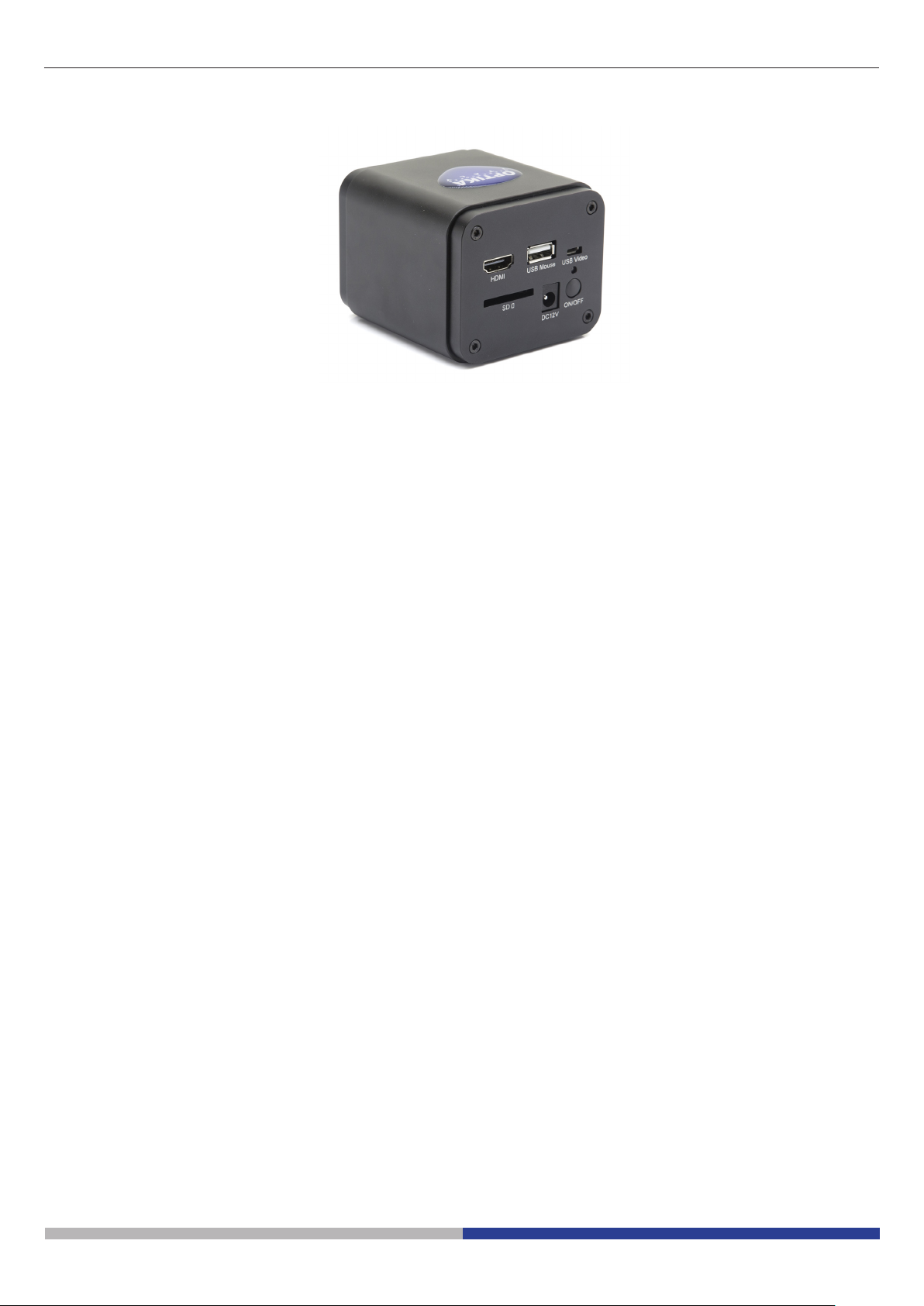
Figure 1 - The Layout of C-HP Rear Cover
① HDMI connector
② USB mouse connector
③ USB PC connector
Before starting the camera, please connect the standard C-HP C-mount camera to the camera adapter and insert it into the microscope’s photo tube which will relay microscope object’s middle image to the camera sensor.
5.2 USB Video Mode
1. Plug 12V/ 1A power cable into DC 12V slot to supply power for the camera. The LED Indicator will turn into
red;
2. Press ON/OFF Button to start the camera and the LED indicator will turn into blue;
3. Plug the USB cable which comes with the camera into USB Video to connect the video to the computer;
4. Open ProView software, start C-HP by clicking the camera model name listed in Camera List. For more
details please refer to the ProView help manual;
5.3 HDMI Mode
④ SD card slot
⑤ Power supply plug
⑥ ON-OFF button
⑥
1. Plug the HDMI cable into the HDMI Port to connect the C-HP camera to HDMI display;
2. Plug a USB mouse into USB Mouse to get control of the camera by using built-in software ProView;
3. Plug 12V/ 1A power adapter into Power Interface to supply power for the camera. The LED Indicator will
turn into red;
4. Insert SD card into SD Card Slot for saving captured images and recorded videos;
5. Press ON/ OFF Buttonto start the camera. The LED Indicator will turn into blue;
6. Move mouse cursor to the left side of the video window, a Camera Control Panel will appear. It includes
Manual/ Automatic Exposure, White Balance, Sharpness and other functions, please refer to2.1 for details;
7. Move mouse cursor to the bottom of the video window and a Camera Control Toolbar will appear. Operations like Zoom In, Zoom Out, Flip, Freeze, Cross Line, Comparison and etc. can be realized. Please refer
to 2.2 for details;
8. Move mouse cursor to the upper side of the video window, a Measurement Toolbar with calibration and
other measurement tools will appear, please refer to 2.3 for details. The measurement data can be output
with *.CSV format.
Page 5
Page 6
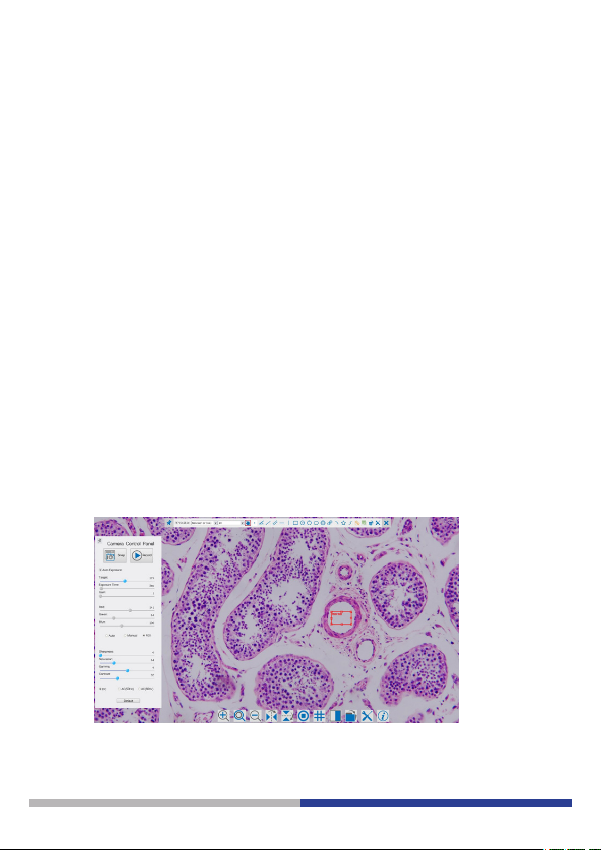
6 C-HP User Interface (UI) and Its Functions
The C-HP UI shown in Fig. 2 includes a Camera Control Panel on the left side of the video window, a Measurement Toolbar on the upper side of the video window, a Camera Control Toolbar on the bottom of the video
window.
Figure 2 - The C-HP Camera Control UI
Notes
1. When users move mouse cursor to the left side of the video window, the Camera Control Panel will pop up
automatically.
2. When users move mouse cursor to the bottom of the video window, the Camera Control Toolbar will pop
up automatically;
3. When user moves mouse cursor to the bottom of the video window, the Camera Control Toolbar will pop
up automatically.
4. Move the mouse cursor to the upper side of the video window: a Measurement Toolbar will pop up for the
calibration and measurement operations. When user left-clicks the Float/Fixed button on the Measurement Toolbar, the Measurement Toolbar will be xed. In this case the Camera Control Panel will not pop up
automatically even if users move mouse cursor to left side of the video windows. Only when user left-clicks
the button on the Measurement Toolbar to exit from measuring procedure will they be able to do other
operations on the Camera Control Panel, or Synthesis Camera Control Toolbar.
During the measuring process, when a specic measuring object is selected an Object Location & Attributes Control Bar will appear for changing location and properties of the selected objects.
Page 6
Page 7
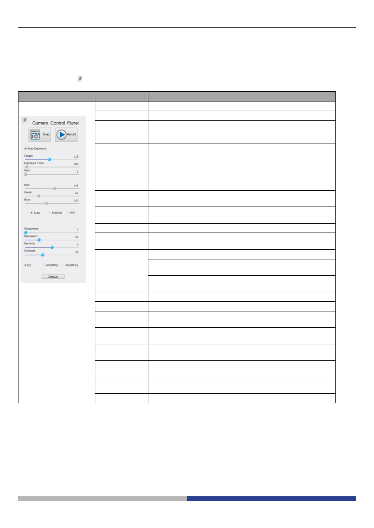
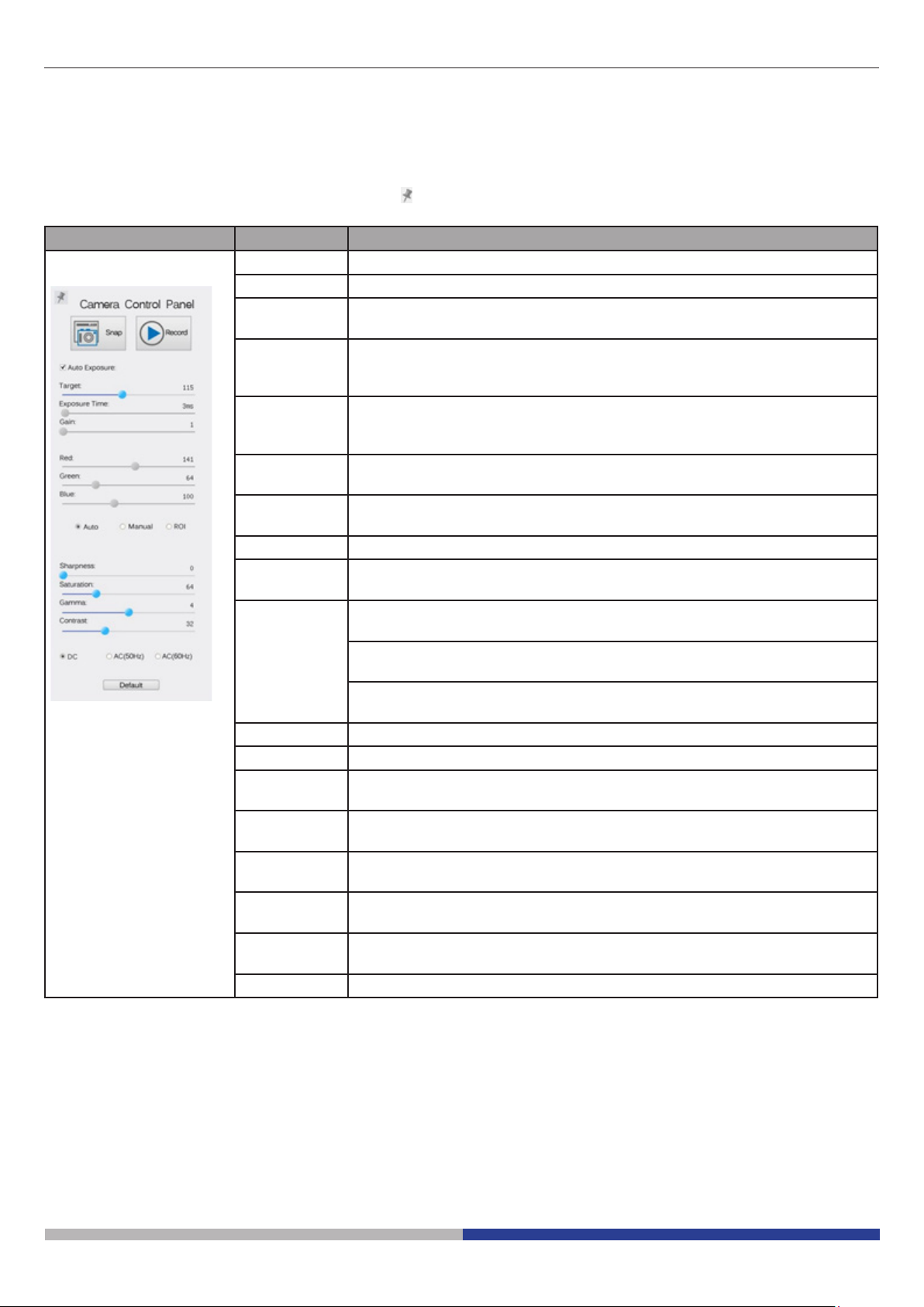
6.1 The Camera Control Panel
The Camera Control Panel controls the camera to achieve the best image quality according to the specic
applications. It will pop up automatically when mouse cursor is moved to the left side of the video window (in
measurement status, the Camera Control Panel will not pop up. Only when measurement process is terminated will the Camera Control Panel pop up by moving mouse cursor to the left side of the video window).
Left-clicking button to achieve Display/ Auto Hide switch of the Camera Control Panel.
Camera Control Panel Function Description
Snap Capture image from the current video window
Record Record video from the current video window
Auto Exposure When Auto Exposure is checked, the system will automatically
adjust exposure time according to the value of exposure compen-
sation
Target Available when Auto Exposure is checked. Slide to left or right to
adjust Target according to the current video brightness to achieve
proper brightness value
Exposure Time Available when Auto Exposure is unchecked. Slide to left or right
to reduce or increase exposure time, adjusting brightness of the
video
Gain Adjust Gain to reduce or increase brightness of video. The Noise
will be reduced or increased accordingly
Red Slide to left or right to decrease or increase the proportion of Red
in RGB on video
Green Green is base for reference and cannot be adjusted
Blue Slide to left or right to decrease or increase the proportion of Blue
in RGB on the video
White Balance Auto: White Balance adjustment according to the window video
Manual: Slide the Red or Blue to manually set the video White
Balance
ROI: Set the White Balance according to the ROI. The ROI can
be resized and moved
Sharpness Adjust Sharpness level of the video window
Saturation Adjust Saturation level of the video window
Gamma Adjust Gamma level of the video. Slide to the right side to increa-
se gamma and to the left to decrease gamma
Contrast Adjust Contrast level of the video. Slide to the right side to increa-
se contrast and to the left to decrease contrast
DC For DC illumination, there will be no uctuation in light source so
no need for compensating light ickering
AC(50HZ) Check AC(50HZ) to eliminate ickering “strap” caused by 50Hz
illumination
AC(60HZ) Check AC(60HZ) to eliminate ickering “strap” caused by 60Hz
illumination
Default Set all the settings in the Camera Control Panel to default values
Page 7
Page 8
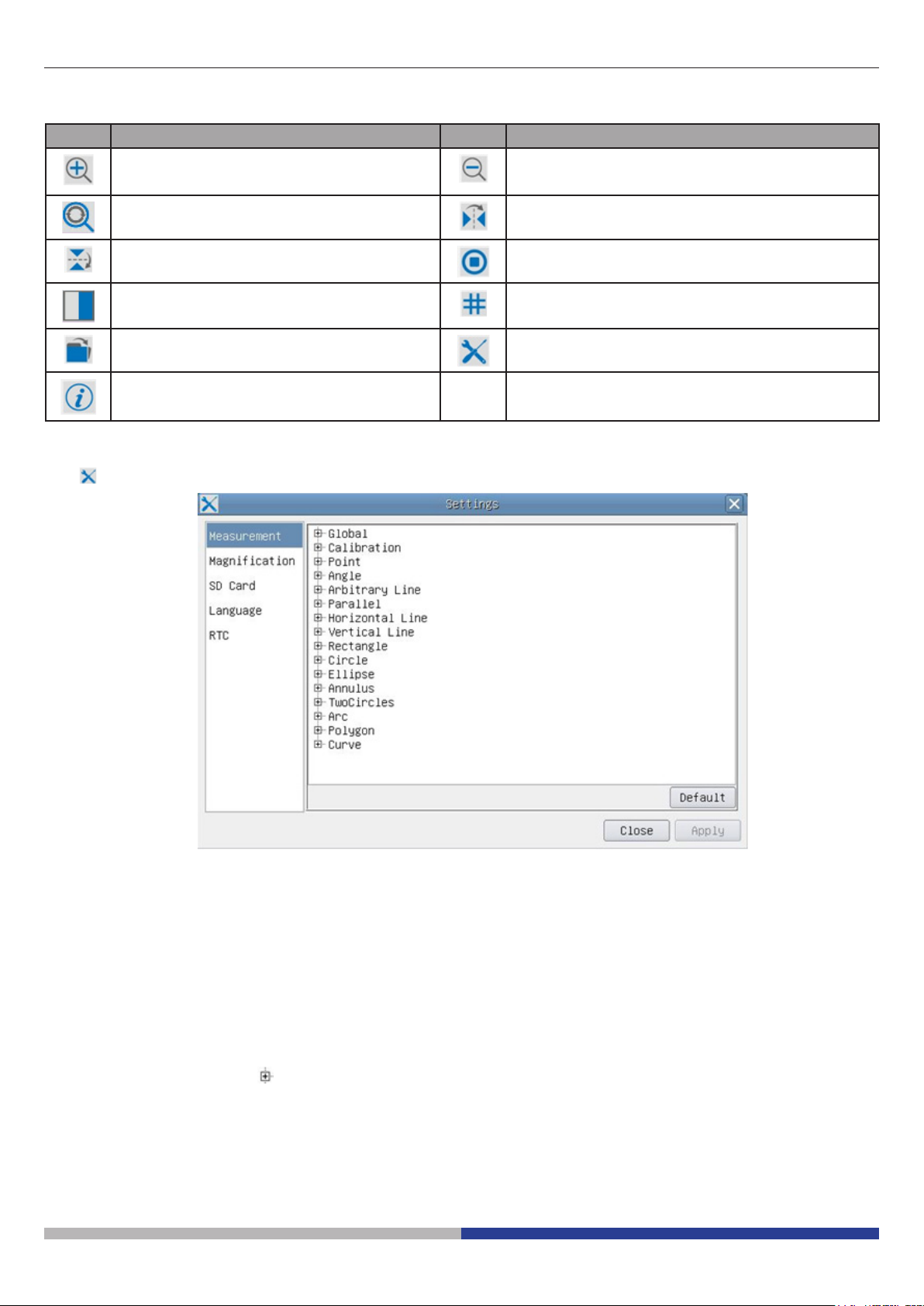
6.2 Icons and Functions of the Camera Control Toolbar
Icon Function Icon Function
Zoom In the Video Window Zoom Out the Video Window
Reset Zoom to Original 1X Horizontal Flip
Vertical Flip Video Freeze
Compare Image with the current video Display Cross Line
Browse Images and Videos in the SD
Settings
Card
Check the Version of ProView
The Setting function is relatively more complicated than the other functions. Here are more info about it:
Figure 3 - Measurement Settings Page
Global: Used for setting digits behind the decimal point for measurement results;
Calibration--> Line Width: Used for dening width of the lines for calibration;
Color: Used for dening color of the lines for calibration;
EndPoint: Type: Used for dening shape of the endpoints of lines for calibration.
Null: means no endpoints, Rectangle means rectangle type of endpoints. It
makes alignment more easily;
Point, Angle, Line, Horizontal Line, Vertical Line, Rectangle, Circle, Ellipse, Annulus, Two Circles, Polygon,
Curve:
Left-click the beside the measuring patterns mentioned above will unfold the corresponding
attribute settings to set the individual property of the measuring objects.
Page 8
Page 9
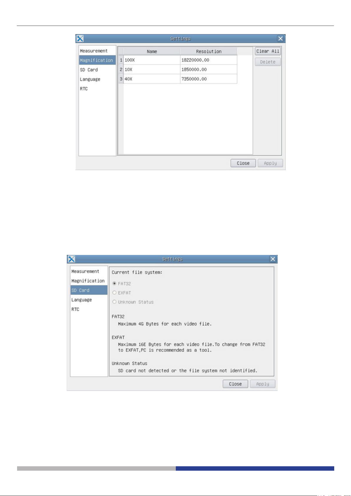
Figure 4 - Magnication Calibration Management Settings Page
Name: Names such as 10X, 40X, 100X are based on magnication of the microscopes. For
continuous zoom microscopes, ensure that the selected magnication coincides with the scale
alignment line on the microscope zoom knob;
Resolution: Pixels per meter. Devices like microscopes have high resolution value;
Clear All: Click the Clear All button will clear the calibrated magnications and resolutions;
Delete: Click Delete to delete the selected item for specic resolution;
Figure 5 - Setting of SD Card Setting Page
Current File System: The maximum le FAT32 can store is of 4G Bytes; for EXFAT, it’s 2048G Bytes.
Suggest converting FAT32 le into EXFAT format on a PC; Unknown Status: SD card
not detected or the le system is not identied.
Page 9
Page 10
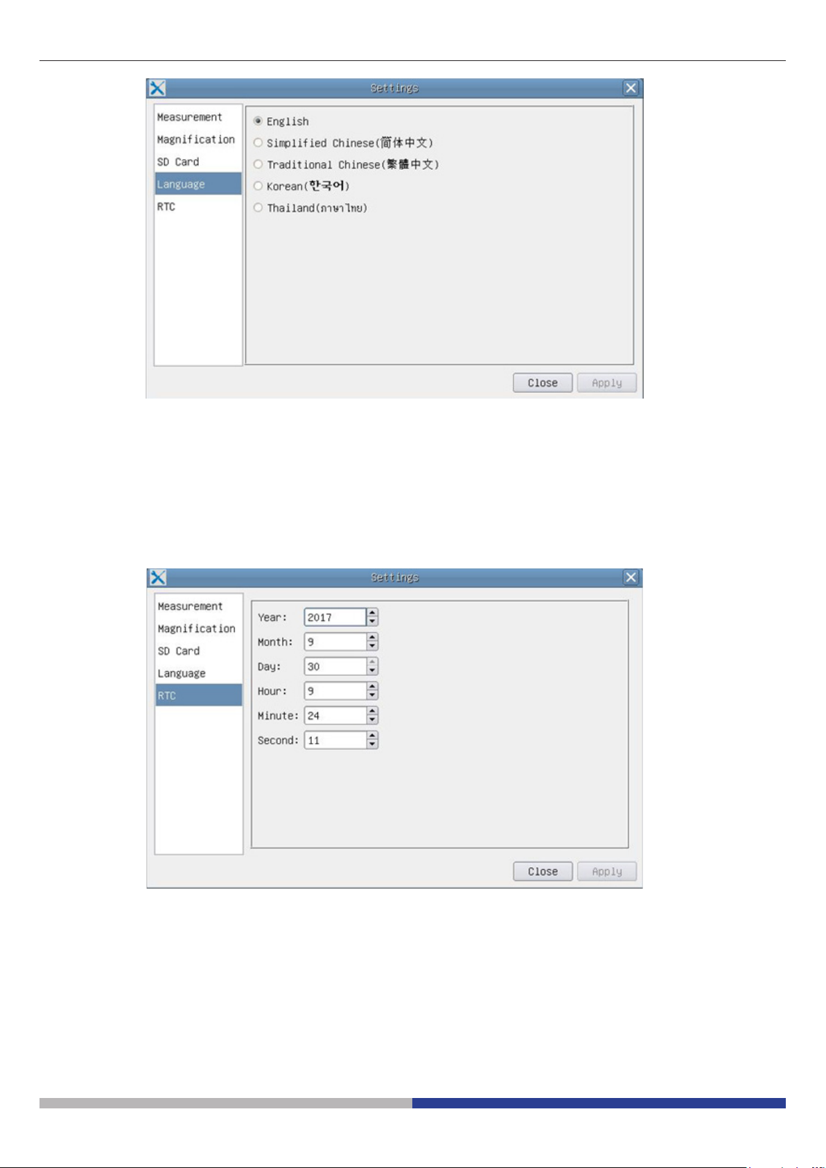
Figure 6 - Setting of Language Selection Setting Page
English: Set language of the whole software into English;
Simplied Chinese: Set language of the whole software into Simplied Chinese;
Traditional Chinese: Set language of the whole software into Traditional Chinese;
Korean: Set language of the whole software into Korean;
Thailand: Set language of the whole software into Thailand;
Year: Current Year
Month: Current Month
Day: Current Day
Hour: Current Hour
Minute: Current Minute
Second: Current Second
Figure 7 - The Real Time Clock Setting
Page 10
Page 11
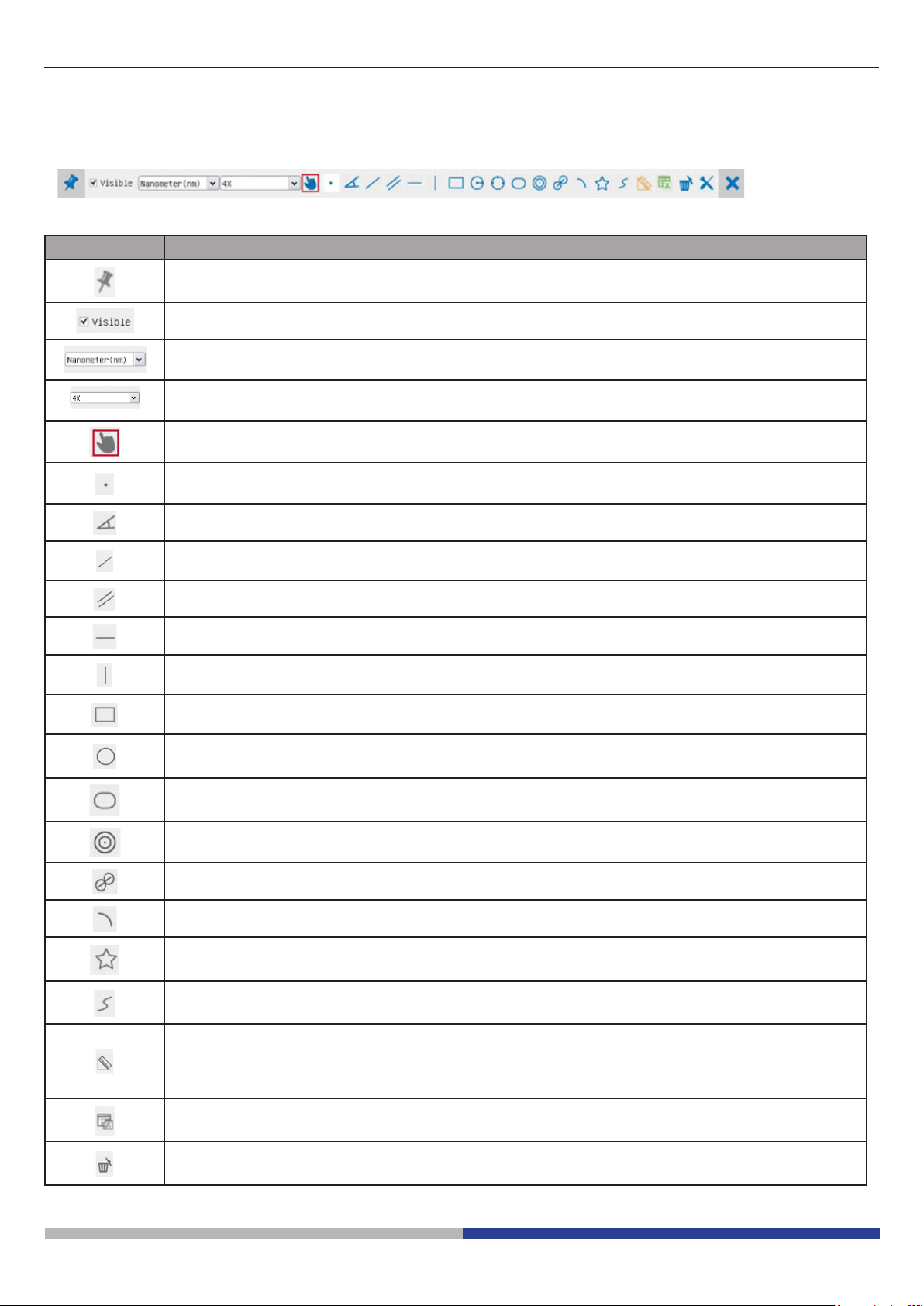
6.3 The Measurement Toolbar
The Measurement Toolbar will pop up when moving mouse cursor to any place near the upper side of the
video window.
Figure 8 - The Measurement Toolbar Button on the Upper Side of the Video window
Icon Function
Float/ Fix switch of the Measurement Toolbar
Dene measuring object in Show up/ Hide mode
Select the desired Measurement Unit
Choose the same Magnication as the microscope to ensure accuracy of measurement result when
measurement unit is not in Pixel units
Object Select
Point
Angle
Arbitrary Line
Parallel
Horizontal Line
Vertical Line
Rectangle
Circle
Ellipse
Annulus
Two Circles and Center Distance
Arc
Polygon
Curve
Make Calibration to determine the corresponding relation between magnication and resolution, this
will establish the corresponding relationship between measurement unit and the sensor pixel size.
Calibration needs to be done with the help of a micrometer. For detailed steps of carrying out calibration please refer to ProView help manual
Export the measurement information to CSV le(*.csv)
Delete All the Measurement Objects
Page 11
Page 12
Setting
Exit from Current Measurement Mode
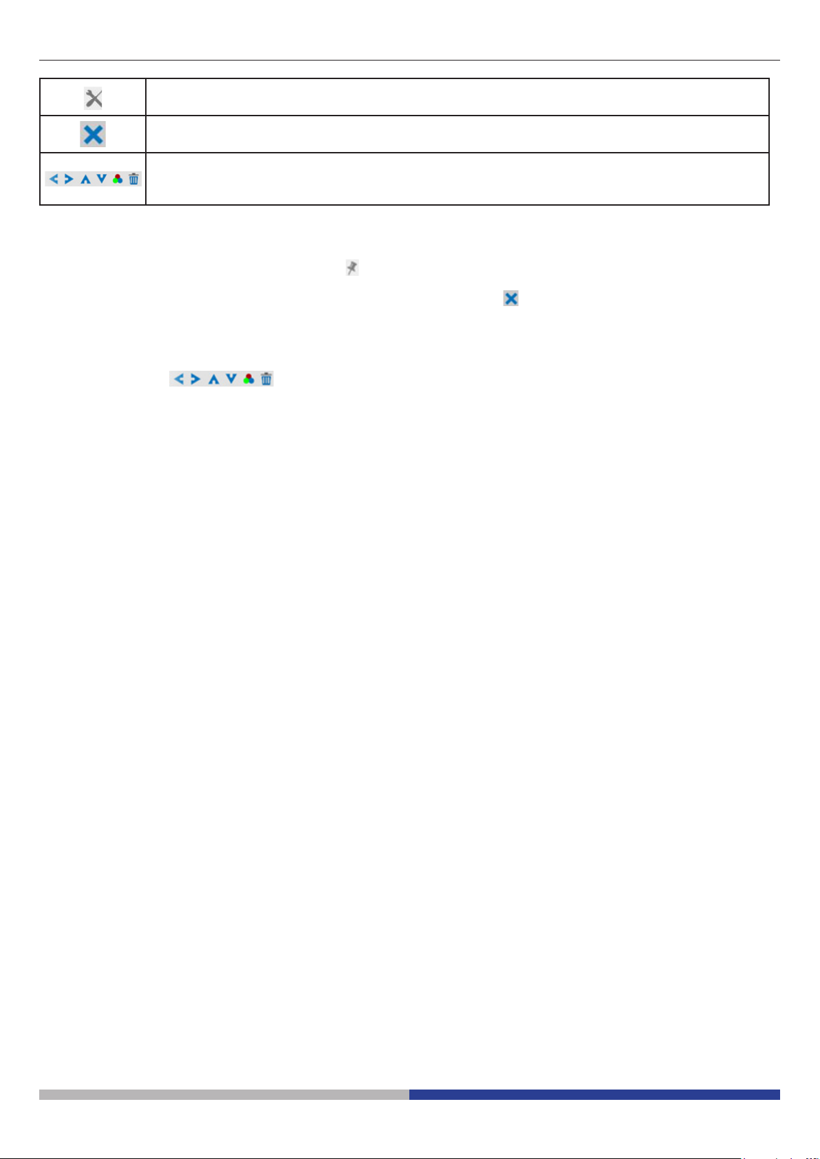
When the measurement ends, left-click on a single measuring object and the Object Location & Properties Control Bar will show up. The icons on the control bar mean Move Left,
Move Right, Move Up, Move Down, Color Adjustment and Delete
Note:
1. When user left-clicks Display/Hide button on the Measurement Toolbar, the Measurement Toolbar will
be xed. In this case the Camera Control Panel will not pop up automatically even if moving mouse cursor
to the left side of the video window. Only when users left click the button on the Measurement Toolbar to
exit from the measurement mode they will be able to doing other operations in the Camera Control Panel,
the Auto Focus Control Panel or the Synthesis Camera Control Toolbar.
2. When a specic measuring object is selected during the measuring process, the Object Location & Attributes Control Bar will appear for changing the object location and properties of the selected
objects.
Page 12
Page 13

7 C-HE Basic features
C-HE is a HDMI + SD card CMOS camera.
HDMI is used as the data transfer interface to HDMI display.
For HDMI output, the Camera Control Panel+ Measurement Toolbar and Camera Control Toolbar are overlaid
on the HDMI screen when the mouse move to the related region.
The USB mouse is used to set the camera.
The C-HE’s basic characteristics are as follows:
For HDMI output:
• All in 1(HDMI + SD card) C-mount camera with Aptina high sensitivity CMOS sensor;
• Built-in mouse control;
• Built-in image capture to SD card;
• Built-in camera control panel, including exposure (manual/auto)/gain, color adjustment, sharpness control;
• Built-in toolbar including zoom, mirror, freeze, cross;
C-HE - SW UI for Mouse Control
Page 13
Page 14

7.1 Quick Instructions for C-HE camera
Figure 8 - The Layout of C-HE Rear Cover
① ②
③
④
① HDMI connector
② USB mouse connector
Before starting the camera, please connect the standard C-HE C-mount camera to the camera adapter and insert it into the microscope’s photo tube which will relay microscope object’s middle image to the camera sensor.
7.1 HDMI Mode
1. Plug the HDMI cable into the HDMI Port to connect the C-HE camera to HDMI display;
2. Plug a USB mouse into USB Mouse to get control of the camera by using built-in software LiteView;
3. Insert SD card into SD Card Slot for saving captured images;
4. Plug 12V/ 1A power adapter into Power Interface to supply power for the camera. The LED Indicator will
turn into blue;
5. Move mouse cursor to the left side of the video window, a Camera Control Panel will appear. It includes
Manual/ Automatic Exposure, White Balance, Sharpness and other functions, please refer to 8.1 for details;
6. Move mouse cursor to the bottom of the video window and a Camera Control Toolbar will appear. Operations like Zoom In, Zoom Out, Flip, Freeze, Cross Line, and etc. can be realized. Please refer to 8.2 for
details;
.
③ Power supply plug
④ SD card slot
Page 14
Page 15

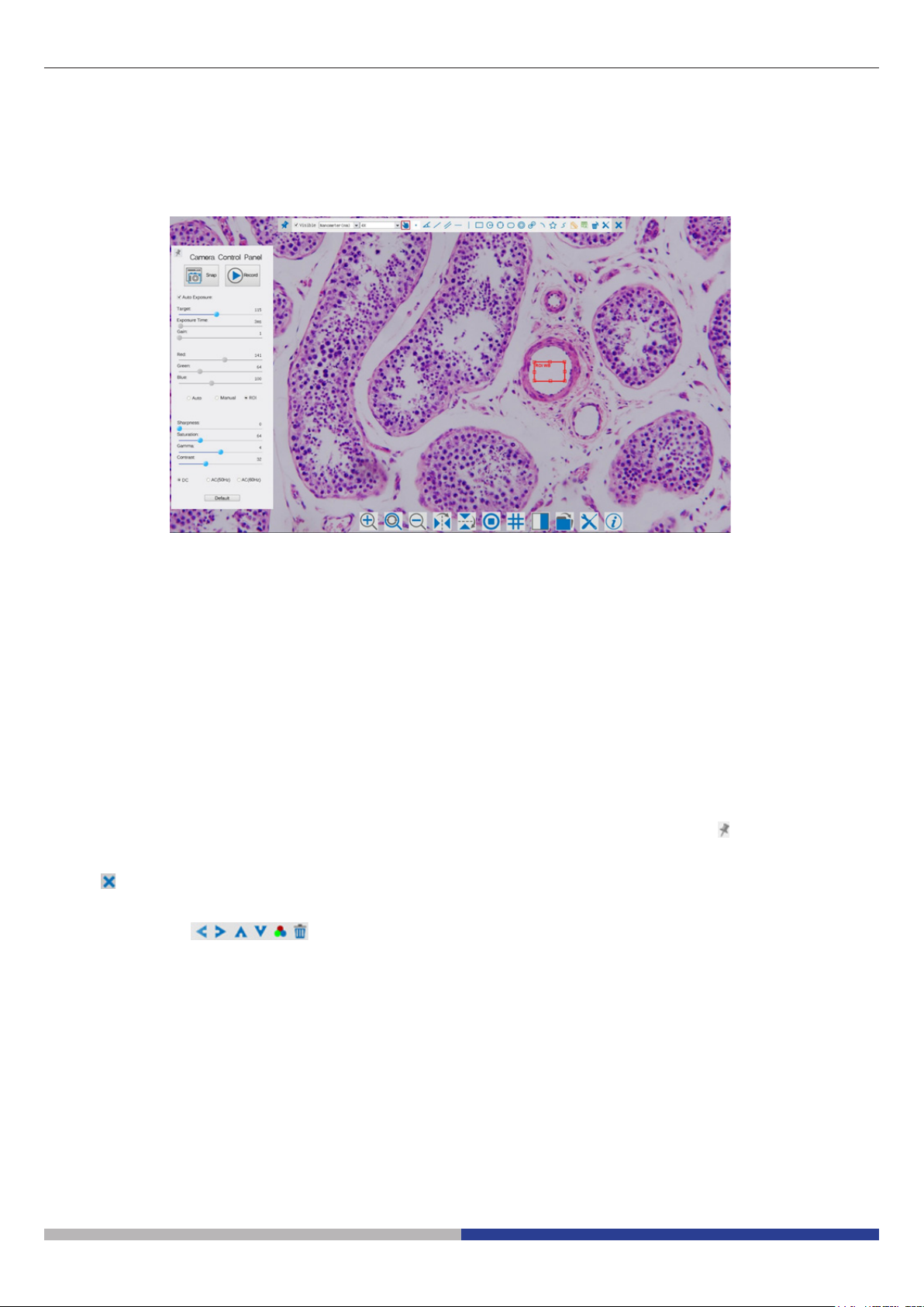
8 C-He User Interface (UI) and Its Functions
The C-He UI shown in Fig. 2 includes a Camera Control Panel on the left side of the video window and a Camera Control Toolbar on the bottom of the video window.
Figure 9 - The C-He Camera Control UI
Notes
1. When users click on the button, the Camera Control Panel will pop up automatically.
2. When users move mouse cursor to the bottom of the video window, the Camera Control Toolbar will pop
up automatically;
Page 15
Page 16

8.1 The Camera Control Panel
The Camera Control Panel controls the camera to achieve the best image quality according to the specic
applications. It will pop up automatically when mouse cursor is moved to the left side of the video window.
Camera Control Panel Function Description
Auto Exposure When Auto Exposure is checked, the system will automatically
adjust exposure time according to the value of exposure compen-
sation
Exposure Time Available when Auto Exposure is unchecked. Slide to left or right
to reduce or increase exposure time, adjusting brightness of the
video
Gain Adjust Gain to reduce or increase brightness of video. The Noise
will be reduced or increased accordingly
Red Slide to left or right to decrease or increase the proportion of Red
in RGB on video
Green Green is base for reference and cannot be adjusted
Blue Slide to left or right to decrease or increase the proportion of Blue
in RGB on the video
White Balance Search a zone on the slide wher only the glass is visible and click
White Balance
Sharpness Adjust Sharpness level of the video window
Denoise Adjust Noise level of the video window
Saturation Adjust Saturation level of the video window
Gamma Adjust Gamma level of the video. Slide to the right side to increa-
se gamma and to the left to decrease gamma
Contrast Adjust Contrast level of the video. Slide to the right side to increa-
se contrast and to the left to decrease contrast
DC For DC illumination, there will be no uctuation in light source so
no need for compensating light ickering
AC(50HZ) Check AC(50HZ) to eliminate ickering “strap” caused by 50Hz
illumination
AC(60HZ) Check AC(60HZ) to eliminate ickering “strap” caused by 60Hz
illumination
Default Set all the settings in the Camera Control Panel to default values
Page 16
Page 17

8.2 Icons and Functions of the Camera Control Toolbar
Icon Function Icon Function
Snap the image and save it to SD card Horizontal Flip
Zoom In the Video Window Video Freeze
Zoom Out the Video Window Display Cross Line
Vertical Flip Toggle ON/OFF Camera Control Panel
Page 17
Page 18

9. C-HPSC / C-HESC
9.1 Overview
HDMI
MONITOR
C-HP / C-HE
CAMERA
9.2 Components
①
MOUNTING
BRACKET
④
③
②
① C-HP / C-HE Camera
② HDMI Monitor
③ Mounting bracket
④ Screws
Page 18
Page 19

9.3 Assembling
1. Screw the four provided allen screws on the back
side of the monitor. (Fig. 1)
2. Screw the two provided cross screws on the back
side of the camera. (Fig. 2)
Fig. 1
3. Install the “C” mount and connect the HDMI and
power cables to monitor and camera.
4. System is ready.
Fig. 2
Page 19
Page 20

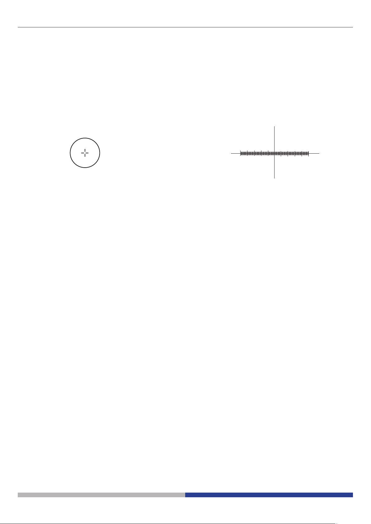
10. Micrometric Slide M-005
Micrometric slide, 26x76mm, with 2 scales
(1mm/100div. for biological microscopes / 10mm/100div. for stereomicroscopes)
0 1 2 3 4 5 6 7 8 9 10
1 DIV=0.01mm
For biological microscopes calibration
1 DIV=0.1mm
For stereo microscopes calibration
Page 20
Page 21

Equipment disposal
Art.13 Dlsg 25 July 2005 N°151. “According to directives 2002/95/EC, 2002/96/EC and 2003/108/EC relating
to the reduction in the use of hazardous substances in electrical and electronic equipment and waste disposal.”
The basket symbol on equipment or on its box indicates that the product at the end of its useful life should be
collected separately from other waste. The separate collection of this equipment at the end of its lifetime is organized and managed by the producer. The user will have to contact the manufacturer and follow the rules that
he adopted for end-of-life equipment collection. The collection of the equipment for recycling, treatment and
environmentally compatible disposal, helps to prevent possible adverse eects on the environment and health
and promotes reuse and/or recycling of materials of the equipment. Improper disposal of the product involves
the application of administrative penalties as provided by the laws in force.
Page 21
Page 22

OPTIKA S.r.l.
®
Via Rigla, 30 - 24010 Ponteranica (BG) - ITALY Tel.: +39 035.571.392
info@optikamicroscopes.com - www.optikamicroscopes.com
OPTIKA Spain
®
spain@optikamicroscopes.com
OPTIKA USA
®
usa@optikamicroscopes.com
OPTIKA China
®
china@optikamicroscopes.com
OPTIKA India
®
india@optikamicroscopes.com
OPTIKA Central America
®
camerica@optikamicroscopes.com
Page 23
Telecamere HDMI – Serie H
MANUALE DI ISTRUZIONI
Modello
C-HP
C-HPSC
C-HE
C-HESC
Ver. 3.0 2019
Page 24

Sommario
1. Avvertenza 25
2. Simboli 25
3. Informazioni sulla sicurezza 25
4. Utilizzo previsto 25
5. C-HP Caratteristiche principali 26
5.1 Istruzioni rapide per la camera C-HP 27
5.2 Modalità USB 27
5.3 Modalità HDMI 27
6. C-HP INTERFACCIA UTENTE (UI) E SUE FUNZIONI 28
6.1 Il Pannello di Controllo Camera 29
6.2 Icone e Funzioni della Barra degli Strumenti Controllo Camera 30
6.3 La Barra degli Strumenti Misurazioni 33
7. C-HE CARATTERISTICHE PRINCIPALI 35
7.1 Istruzioni rapide per la camera C-HE 36
7.1 Modalità HDMI 36
8 C-HE INTERFACCIA UTENTE (UI) E SUE FUNZIONI 37
8.1 Il Pannello Controllo Camera 38
8.2 Icone e Funzioni della Barra degli Strumenti Controllo Camera 39
9. C-HPSC / C-HESC 40
9.1 Panoramica del sistema 40
9.2 Componenti 40
9.3 Assemblaggio 41
10. VETRINO MICROMETRICO M-005 42
SMALTIMENTO 43
Pagina 24
Page 25

1. Avvertenza
Questo microscopio è uno strumento scientico di alta precisione, progettato per durare a lungo con una minima
manutenzione; la realizzazione è secondo i migliori standard ottici e meccanici, per poter essere utilizzato
quotidianamente. Vi ricordiamo che questo manuale contiene informazioni importanti per la sicurezza e per la
manutenzione dello strumento, e deve quindi essere messo a disposizione di coloro che lo utilizzeranno.
Decliniamo ogni responsabilità derivante da un utilizzo dello strumento non indicato nel presente manuale
2. Simboli
La seguente tabella riporta i simboli utilizzati in questo manuale.
PERICOLO
Questo simbolo indica un rischio potenziale ed avverte di procedere con cautela.
SHOCK ELETTRICO
Questo simbolo indica un rischio di shock elettrico
3. Informazioni sulla sicurezza
Per evitare shock elettrici
Prima di collegare il cavo di alimentazione alla presa elettrica, assicurarsi che il voltaggio della rete locale
coincida con il voltaggio dello strumento e che l’interruttore dell’illuminazione sia nella posizione “OFF”.
Gli utenti dovranno seguire tutte le norme di sicurezza locali. Lo strumento è certicato CE. In ogni caso, gli
utilizzatori sono gli unici responsabili per un utilizzo sicuro dello strumento. Per l’utilizzo in sicurezza dello
strumento è importante attenersi alle seguenti istruzioni e leggere il manuale in tutte le sue parti.
4. Utilizzo previsto
Solo per ricerca. Non è previsto alcun utilizzo di questo strumento per uso diagnostico.
Pagina 25
Page 26

5. C-HP Caratteristiche principali
La C-HP è una telecamera CMOS ad interfaccia multipla (HDMI + USB2.0 + SD card).
HDMI e USB2.0 vengono usati come interfaccia trasferimento dati ad un monitor HDMI o ad un computer
Nell’interfaccia HDMI, il Pannello di Controllo Telecamera + Barra degli strumenti Misurazione e la Barra degli
strumenti Controllo Camera sono in sovraimpressione sul monitor HDMI quando il mouse si sposta sulla zona
del monitor corrispondente; in questo caso il mouse USB viene usato per impostare i parametri della telecamera, navigare e confrontare le immagini acquisite, riprodurre video, ed eseguire misurazioni.
Nell’interfaccia USB Video, collegare il cavo micro USB nel connettore USB video posto sul pannello della
telecamera e in una porta USB del computer; a questo punto l’immagine verrà trasferita al computer tramite il
software ProView. Con ProView, si potrà controllare la telecamera, elaborare video ed immagini esattamente
come per tutte le altre telecamere della serie di OPTIKA.
Le caratteristiche principali della C-HP sono le seguenti:
Per l’interfaccia HDMI:
• Telecamera passo “C” (HDMI + USB + SD card) con sensore Sony CMOS ad alta sensibilità;
• Uscita contemporanea HDMI & USB;
• Controllo via mouse integrato;
• Controllo integrato di cattura immagine e video su SD card;
• Pannello di controllo della telecamera incorporato, che include controllo di esposizione (manuale/auto)/
guadagno, bilanciamento del bianco (bloccabile), regolazione colori, nitidezza;
• Misurazione su immagini e video integrato;
• Barra degli strumenti integrata che include zoom, ribaltamento immagine, confronto, freeze, croce, funzioni
di ricerca immagine;
• Ricerca, visualizzazione e riproduzione di immagini e video integrata;
• Orologio in tempo reale (RTC)
For USB Video output:
• Sensore a colori Ultra-ne con perfetta capacità di riproduzione del colore (USB);
• Software di elaborazione per immagini e video ProView, che incorpora elaborazioni professionali quali
misurazioni 2D, HDR, composizione immagini, EDF (Extended Depth of Focus), segmentazione e conta di
immagini, sovrapposizione immagini, composizione colori e denoising (USB);
• Supporta protocolli UVC standard per Windows (USB);
C-HP - Interfaccia Utente con Controllo Mouse
Pagina 26
Page 27

5.1 Istruzioni rapide per la camera C-HP
①
②
③
⑤
⑥
④
Figura 1 - Pannello posteriore della C-HP
① Connettore HDMI
② Connettore mouse USB
③ Connettore USB a PC
Prima di accendere la telecamera, collegare l’adattatore passo “C” alla telecamera e inserire l’adattatore sulla
porta trinoculare del microscopio.
5.2 Modalità USB
1. Collegare il cavo di alimentazione 12V/ 1A nel connettore DC 12V per alimentare la camera. Il LED Indicator diventerà rosso;
2. Premere il tasto ON/OFF per accendere la camera; il LED Indicator diventerà blu;
3. Collegare il cavo USB in dotazione con la camera nella porta USB Video per collegare l’uscita video al
computer;
4. Avviare il software ProView, attivare C-HP cliccando il nome della telecamera nell’elenco Camera List. Per
maggiori dettagli consultare il manuale di istruzioni di ProView;
5.3 Modalità HDMI
④ Alloggiamento SD card
⑤ Connettore alimentatore
⑥ tasto ON-OFF
1. Collegare il cavo HDMI nella porta HDMI per collegare la camera C-HP al monitor HDMI;
2. Collegare il mouse USB nella porta USB Mouse per ottenere il controllo della camera mediante il software
integrato ProView;
3. Collegare il cavo di alimentazione 12V/ 1A nel connettore DC 12V per alimentare la camera. Il LED Indicator diventerà rosso;
4. Inserire la scheda SD nella fessura SD per salvare immagini e video acquisiti;
5. Premere il tasto ON/OFF per accendere la camera; il LED Indicator diventerà blu;
6. Muovere il cursore del mouse sul lato sinistro della nestra video; apparirà il Pannello di Controllo Camera.
Include Manual/ Automatic Exposure, White Balance, Sharpness ed altre funzioni, consultare il paragrafo
2.1 per maggiori dettagli;
7. Muovere il cursore del mouse sulla parte bassa della nestra video e apparirà una Barra degli Strumenti
Controllo Camera. Sono possibili operazioni quali Zoom In, Zoom Out, Flip, Freeze, Cross Line, Comparison ed altre. Consultare il paragrafo 2.2 per maggiori dettagli;
8. Muovere il cursore del mouse sulla parte alta della nestra video; apparirà una Barra degli Strumenti Misurazioni con funzioni di calibrazione e di altri strumenti di misura, consultare il paragrafo 2.3 per maggiori
dettagli. I dati delle misurazioni possono essere esportati con formato *.CSV.
Pagina 27
Page 28

6. C-HP Interfaccia utente (UI) e sue funzioni
L’Interfaccia Utente C-HP mostrata in Fig. 2 include un Pannello di Controllo Camera sul lato sinistro del video,
una Barra degli Strumenti Misurazioni nella parte alta del video ed una Barra degli Strumenti Controllo Camera
nella parte inferiore.
Figura 2 - L’interfaccia Utente del Camera Control della C-HP
Note
1. Quando si sposta il cursore verso la parte sinistra del monitor, il Pannello di Controllo Camera si attiva
automaticamente.
2. Quando si sposta il cursore verso la parte bassa del monitor, la Barra degli Strumenti Controllo Camera si
attiva automaticamente;
3. Quando si sposta il cursore verso la parte alta del monitor, la Barra degli Strumenti Controllo Camera si
attiva automaticamente.
4. Spostare il cursore verso la parte alta del monitor, una Barra degli Strumenti Misurazioni si attiva per le
operazioni di calibrazione e di misurazioni. Quando si clicca con il tasto sinistro del mouse sul tasto Bloc-
ca/Nascondi sulla Barra degli Strumenti Misurazioni, questa verrà bloccata. In questo caso il Pannello
di Controllo Camera non si attiva automaticamente anche quando l’operatore sposta il cursore sul lato
sinistro del monitor. Solo quando l’operatore clicca sul tasto sulla Barra degli Strumenti Misurazioni per abbandonare la sessione di misurazioni, sarà possibile eettuare altre operazioni sul Pannello di
Controllo Camera, o sulla Barra degli Strumenti Controllo Camera. Durante il processo di misurazioni,
quando uno specico oggetto di misura è selezionato una Barra di Controllo Posizione Oggetto & Attributi
appare per modicare la posizione e le proprietà degli oggetti selezionati
.
Pagina 28
Page 29
6.1 Il Pannello di Controllo Camera
Il Pannello di Controllo Camera controlla la camera per ottenere la migliore qualità dell’immagine in funzione
dell’applicazione specica. Appare automaticamente quando il cursore del mouse viene spostato nella parte
sinistra del monitor (durante la sessione di misura il Pannello di Controllo Camera non si attiva. Solo quando
la sessione di misura è terminata il Pannello di Controllo Camera si attiva muovendo il cursore del nella parte
sinistra del monitor). Fare doppio clic sul tasto tper attivare la funzione Mostra/Nascondi Automaticamente
del Pannello di Controllo Camera.
Pannello Controllo Funzione Descrizione
Snap Cattura l’immagine attualmente visualizzata sul monitor
Record Registra un video dalla videata attualmente mostrata sul monitor
Auto Exposure
Target Attivo quando Auto Exposure è attivato. Spostare a destra o a sinistra per
Exposure
Time
Gain Regolare il Gain (Guadagno) per ridurre o aumentare la luminosità a moni-
Red Spostare a sinistra o a destra per ridurre o aumentare il valore del Rosso in
Green Verde è la base di riferimento e non può essere regolato
Blue Spostare a sinistra o a destra per ridurre o aumentare il valore del Blu in
White Balan-
ce
Sharpness Regola il livello di Nitidezza visualizzato a monitor
Saturation Regola il livello di Saturazione visualizzato a monitor
Gamma Regola il livello di Gamma visualizzato a monitor. Spostare a destra per
Contrast Regola il livello di Contrasto visualizzato a monitor. Spostare a destra per
DC Per l’illuminazione DC, non ci sono uttuazioni nella sorgente luminosa
AC(50HZ) Abilitare AC(50HZ) per eliminare lo sfarfallio della luce causato da illumina-
AC(60HZ) AC(60HZ) Abilitare AC(60HZ) per eliminare lo sfarfallio della luce
Default Riporta tutti i valori del Pannello di Controllo Camera ai valori di default
Quando Auto Exposure è attivato, il sistema adatta automaticamente il
tempo di esposizione in funzione del valore di compensazione esposizione
adattare il Target alla luminosità attuale del monitor per ottenere il valore
ottimale di luminosità
Exposure Time Attivo quando Auto Exposure è disattivato. Spostare a sinistra o a destra per ridurre o aumentare il tempo di esposizione, regolando
la luminosità a monitor
tor. Il rumore verrà ridotto o aumentato di conseguenza
RGB sul monitor
RGB sul monitor
Auto:regolazione del Bilanciamento del Bianco in base alla visualizzazione
a monitor
Manual: Spostare il Red o il Blue per impostare manualmente il Bilanciamento del Bianco
ROI: Imposta il Bilanciamento del Bianco in funzione della ROI (Region Of
Interest). La ROI può essere ridimensionata e spostatad
aumentare e a sinistra per diminuire il gamma.
aumentare e a sinistra per diminuire il contrasto
quindi non sono necessarie compensazioni per lo sfarfallio della luce
zione a 50Hz
causato da illuminazione a 60Hz
Pagina 29
Page 30

6.2 Icone e Funzioni della Barra degli Strumenti Controllo Camera
Icona Funzione Icona Funzione
Aumenta lo Zoom a Monitor Diminuisce lo Zoom a Monitor
Ripristina lo Zoom al valore originale di 1X Ribalta Orizzontale
Ribalta Verticale Congela il Video
Confronta Immagine con quella attualmente
visualizzata a monitor
Sfoglia Immagini e Video archiviati sulla SD
Card
Informazioni sulla Versione di ProView
Mostra il Crocelo
Impostazioni
Le funzioni di Impostazioni sono un pochino più complicate rispetto alle altre funzioni. Di seguito alcune
informazioni aggiuntive in merito:
Figura 3 - Pagina Impostazioni Misurazioni
Global: Usato per impostare il numero di decimali dopo la virgola;
Calibration--> Line Width: Usato per denire lo spessore delle linee di calibrazione;
Color: Usato per denire il colore delle linee di calibrazione;
EndPoint:
Type: Usato per denire la forma dei punti terminali delle line di calibrazione.
Null: Indica nessun punto terminale
Rectangle: indica un terminale rettangolare. Consente un allineamento più semplice
Point, Angle, Line, Horizontal Line, Vertical Line, Rectangle, Circle, Ellipse, Annulus, Two Cir-
cles, Polygon, Curve: Fare clic col tasto sinistro del mouse su accanto al modello di misura
indicato sopra per elencare le impostazioni relative per impostare le singole proprietà delle varie
misurazioni
Pagina 30
Page 31
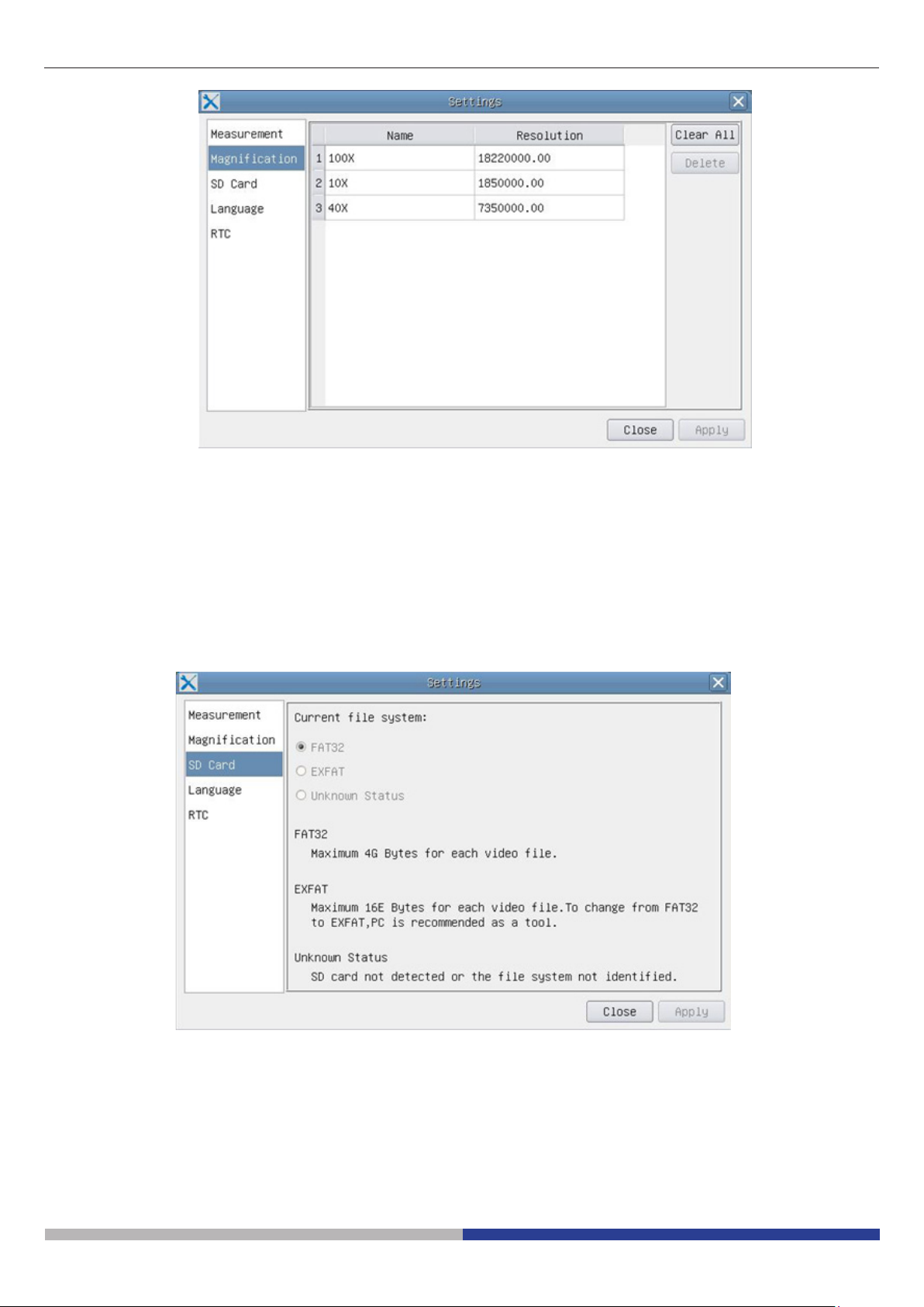
Figura 4 - Pagina di Impostazioni degli Ingrandimenti di Calibrazione
Name: I nomi 10X, 40X, 100X sono basati sugli ingrandimenti del microscopio. Per microscopi con
zoom in continuo, vericare che l’ingrandimento selezionato coincida con la scala sul selettore
del microscopio;
Resolution: Pixels per metro. Dispositivi quali i microscopi hanno alti valori di risoluzione;
Clear All: Cliccare il tasto Clear All per eliminare gli ingrandimenti calibrati e le risoluzioni;
Delete: Cliccare il tasto Delete per eliminare l’item selezionato per quella specica risoluzione;
Figura 5 - Pagina di Impostazioni della SD
Current File System: La dimensione massima che un le FAT32 può archiviare è 4G Bytes; per EXFAT
è 2048G Bytes. Si suggerisce di convertire un le FAT32 in format EXFAT su PC;
Unknown Status: SD card non rilevata o il le di Sistema non è identicato.
Pagina 31
Page 32

Figure 6 - Pagina di Impostazioni della Selezione Lingue
English: Imposta la lingua dell’intero sistema su Inglese;
Simplied Chinese: Imposta la lingua dell’intero sistema su Cinese Semplicato;
Traditional Chinese: Imposta la lingua dell’intero sistema su Cinese Tradizionale;
Korean: Imposta la lingua dell’intero sistema su Coreano;
Thailand: Imposta la lingua dell’intero sistema su Tailandese;
Year: Anno
Month: Mese
Day: Giorno
Hour: Ora
Minute: Minuti
Second: Secondi
Figura 7 - Impostazioni dell’Orologio in Tempo Reale (RTC)
Pagina 32
Page 33

6.3 La Barra degli Strumenti Misurazioni
La Barra degli Strumenti Misurazioni appare quando si sposta il cursore in un qualsiasi punto vicino alla parte
superiore del monitor
Figure 8 - La Barra degli Strumenti Misurazioni
Icona Funzione
Attiva il tasto Nascondi/Blocca della Barra degli Strumenti Misurazioni
Denisce le misurazioni attive in modalità Mostra/Nascondi
Seleziona l’Unità di Misura desiderata
Seleziona lo stesso Ingrandimento in uso sul microscopio per assicurare precisione del risultato di
misura quando l’unità di misura non è espressa in Pixel
Seleziona Oggetto
Punto
Angolo
Linea Arbitraria
Parallele
Linea Orizzontale
Linea Verticale
Rettangolo
Cerchio
Ellisse
Anello
Due Cerchi e Distanza dal Centro
Arco
Poligono
Curva
Eettua la calibrazione per determinare la relazione corrispondente tra ingrandimento e risoluzione,
ciò stabilirà la relazione corrispondente tra unità di misura e dimensione del pixel del sensore. La
calibrazione deve essere eseguita con l’aiuto di un micrometro. Per le fasi dettagliate di esecuzione
della calibrazione, consultare il manuale di ProView
Esporta le informazioni di misura ad un le CSV(*.csv)
Elimina tutte le Misurazioni
Pagina 33
Page 34

Impostazioni
Esci dal Modo di Misurazione Attuale
Quando la misurazione termina, fare doppio clic col tasto sinistro del mouse su una singola misurazione e la Barra di Controllo Posizione Oggetto & Attributi appare. Le icone sulla barra di controllo signicano Sposta a Sinistra, Sposta a Destra, Sposta Su, Sposta Giu, Regolazione Colori e Elimina.
Note:
1. W Quando l’utilizzatore clicca con il tasto sinistro del mouse il tasto Mostra/Nascondi sulla Barra degli
Strumenti Misurazioni, la Barra degli Strumenti Misurazioni viene bloccata. In questo caso il Pannello di
Controllo Camera non si attiva automaticamente anche se si sposta il cursore del mouse sulla parte sinistra del monitor. Solo quando l’utilizzatore clicca con il tasto sinistro del mouse il tasto sulla Barra degli
Strumenti Misurazioni per uscire dalla modalità misurazione, sarà possibile eettuare altre operazioni nel
Pannello di Controllo Camera o nella Barra degli Strumenti Controllo Camera.
2. Quando uno specico oggetto di misura viene selezionato durante il processo di misura, la Barra di Controllo Posizione Oggetto & Attributi appare per modicare la posizione e le proprietà degli
oggetti selezionati.
Pagina 34
Page 35

7. C-HE Caratteristiche principali
La C-HE è una telecamera CMOS HDMI + SD card.
HDMI è usato come interfaccia trasferimento dati ad un monitor HDMI.
Nell’interfaccia HDMI, il Pannello di Controllo Telecamera e la Barra degli strumenti Controllo Camera sono in
sovraimpressione sul monitor HDMI quando il mouse si sposta sulla zona del monitor corrispondenten.
Il mouse USB è usato per controllare la telecamera.
Le funzioni principali della C-HE sono le seguenti:
Per l’interfaccia HDMI:
• Telecamera integrata (HDMI + SD card) a passo “C” con sensore Aptina CMOS ad alta sensibilità;
• Controllo via mouse integrato;
• Controllo integrato di cattura immagine su SD card;
• Pannello di controllo della telecamera incorporato, che include controllo di esposizione (manuale/auto)/guadagno, bilanciamento del bianco, regolazione colori, nitidezza;
• Barra degli strumenti integrata che include zoom, ribaltamento immagine, freeze, croce;
C-HE - Interfaccia Utente con Controllo Mouse
Pagina 35
Page 36

7.1 Istruzioni rapide per la camera C-HE
Figura 8 - Pannello posteriore della C-HE
① ②
③
④
① Connettore HDMI
② Connettore mouse USB
Prima di accendere la telecamera, collegare l’adattatore passo “C” alla telecamera e inserire l’adattatore sulla
porta trinoculare del microscopio.
7.1 Modalità HDMI
1. Collegare il cavo HDMI nella porta HDMI per collegare la camera C-HE al monitor HDMI;
2. Collegare il mouse USB nella porta USB Mouse per ottenere il controllo della camera mediante il software
integrato LiteView;
3. Inserire la scheda SD nella fessura SD per salvare le immagini acquisite;
4. Collegare il cavo di alimentazione 12V/ 1A nel connettore DC 12V per alimentare la camera. Il LED Indica-
tor diventerà blu;
5. Muovere il cursore del mouse sul lato sinistro della nestra video; apparirà il Pannello di Controllo Camera.
Include Manual/ Automatic Exposure, White Balance, Sharpness ed altre funzioni, consultare il paragrafo
8.1 per maggiori dettagli;
6. 15. Muovere il cursore del mouse sulla parte bassa della nestra video e apparirà una Barra degli Strumenti Controllo Camera. Sono possibili operazioni quali Zoom In, Zoom Out, Flip, Freeze, Cross Line ed
altre. Consultare il paragrafo 8.2 fper maggiori dettagli;
.
③ Connettore alimentatore
④ Alloggiamento SD card
Pagina 36
Page 37
8 C-HE Interfaccia utente (UI) e sue funzioni
L’Interfaccia Utente (UI) mostrato in Fig. 9 include un Pannello di Controllo Camera sulla parte sinistra del monitor e una Barra Strumenti Controllo Camera nella parte inferiore del monitor.
Figura 9 - L’Interfaccia Utente Controllo Camera della C-HE
Note
1. Quando l’utente clicca sul tasto , il Pannello Controllo Camera appare automaticamente.
2. Quando si sposta il cursore verso la parte bassa del monitor, la Barra degli Strumenti Controllo Camera si
attiva automaticamente;
Pagina 37
Page 38
8.1 Il Pannello Controllo Camera
Il Pannello di Controllo Camera controlla la camera per ottenere la migliore qualità dell’immagine in funzione
dell’applicazione specica. Appare automaticamente quando il cursore del mouse viene spostato nella parte
sinistra del monitor.
Pannello Controllo Funzione Descrizione
Auto Exposure Quando Auto Exposure è attivato, il sistema adatta automatica-
mente il tempo di esposizione in funzione del valore di compensazione esposizione
Exposure Time Exposure Time Attivo quando Auto Exposure è disattivato.
Spostare a sinistra o a destra per ridurre o aumentare il tempo di
esposizione, regolando la luminosità a monitor
Gain Regolare il Gain (Guadagno) per ridurre o aumentare la luminosi-
tà a monitor. Il rumore verrà ridotto o aumentato di conseguenza
Red Spostare a sinistra o a destra per ridurre o aumentare il valore del
Rosso in RGB sul monitor
Green Verde è la base di riferimento e non può essere regolato
Blue Spostare a sinistra o a destra per ridurre o aumentare il valore del
Blu in RGB sul monitor
White Balance Cercare una zona dove è visibile solo vetro e cliccare White
Balance
Sharpness Regola il livello di Nitidezza visualizzato a monitor
Denoise Regola il livello di Rumore visualizzato a monitor
Saturation Regola il livello di Saturazione visualizzato a monitor
Gamma Regola il livello di Gamma visualizzato a monitor. Spostare a
destra per aumentare e a sinistra per diminuire il gamma.
Contrast Regola il livello di Contrasto visualizzato a monitor. Spostare a
destra per aumentare e a sinistra per diminuire il contrasto
DC Per l’illuminazione DC, non ci sono uttuazioni nella sorgente
luminosa quindi non sono necessarie compensazioni per lo sfarfallio della luce
AC(50HZ) Abilitare AC(50HZ) per eliminare lo sfarfallio della luce causato da
illuminazione a 50Hz
AC(60HZ) AC(60HZ) Abilitare AC(60HZ) per eliminare lo sfarfallio della
luce causato da illuminazione a 60Hz
Default Riporta tutti i valori del Pannello di Controllo Camera ai valori di
default
Pagina 38
Page 39

8.2 Icone e Funzioni della Barra degli Strumenti Controllo Camera
Icona Funzione Icona Funzione
Cattura l’immagine e la salva su SD card Ribalta Orizzontale
Aumenta lo Zoom a Monitor Congela il Video
Diminuisce lo Zoom a Monitor Mostra il Crocelo
Ribalta Verticale Attiva/Disattiva il Pannello Controllo Camera
Pagina 39
Page 40

9. C-HPSC / C-HESC
9.1 Panoramica del sistema
MONITOR
HDMI
TELECAMERA
C-HP / C-HE
9.2 Componenti
①
STAFFA DI
MONTAGGIO
④
③
②
① Telecamera C-HP / C-HE
② Monitor HDMI
③ Staa di ssaggio
④ Viti
Pagina 40
Page 41

9.3 Assemblaggio
1. Avvitare le quattro viti a brugola in dotazione allla
parte posteriore del monitor. (Fig. 1)
2. Avvitare le due viti a croce in dotazione ai due fori
sulla telecamera. (Fig. 2)
Fig. 1
3. Procedere al montaggio del passo “C” e al colle-
gamento dei cavi di alimentazione e HDMI.
4. Il sistema è pronto.
Fig. 2
Pagina 41
Page 42
10. Vetrino Micrometrico M-005
Vetrino micrometrico, 26x76mm, con 2 scale
(1mm/100div. per microscopi biologici / 10mm/100div. per stereomicroscopi)
0 1 2 3 4 5 6 7 8 9 10
1 DIV=0.01mm
Per la calibrazione di un microscopio biologico
1 DIV=0.1mm
Per la calibrazione di uno stereo microscopio
Pagina 42
Page 43

Smaltimento
Ai sensi dell’articolo 13 del decreto legislativo 25 luglio 2005 n°151. “Attuazione delle direttive 2002/95/CE,
2002/96/CE e 2003/108/CE, relative alla riduzione dell’uso di sostanze pericolose nelle apparecchiature elettriche
ed elettroniche, nonché allo smaltimento dei riuti”.
Il simbolo del cassonetto riportato sulla apparecchiatura o sulla sua confezione indica che il prodotto alla ne
della propria vita utile deve essere raccolto separatamente degli altri riuti. La raccolta dierenziata della presente
apparecchiatura giunta a ne vita è organizzata e gestita dal produttore. L’utente che vorrà disfarsi della presente
apparecchiatura dovrà quindi contattare il produttore e seguire il sistema che questo ha adottato per consentire la
raccolta separata dell’apparecchiatura giunta a ne vita. L’adeguata raccolta dierenziata per l’avvio successivo
della apparecchiatura dismessa al riciclaggio, al trattamento e allo smaltimento ambientalmente compatibile
contribuisce ad evitare possibili eetti negativi sull’ambiente e sulla salute e favorisce il reimpiego e/o riciclo
dei materiali di cui è composta l’apparecchiatura. Lo smaltimento abusivo del prodotto da parte del detentore
comporta l’applicazione delle sanzioni amministrative previste dalla normativa vigente.
Pagina 43
Page 44

OPTIKA S.r.l.
®
Via Rigla, 30 - 24010 Ponteranica (BG) - ITALY Tel.: +39 035.571.392
info@optikamicroscopes.com - www.optikamicroscopes.com
OPTIKA Spain
®
spain@optikamicroscopes.com
OPTIKA USA
®
usa@optikamicroscopes.com
OPTIKA China
®
china@optikamicroscopes.com
OPTIKA India
®
india@optikamicroscopes.com
OPTIKA Central America
®
camerica@optikamicroscopes.com
 Loading...