

Optika B-500Ti-2, B-500Ti-3, B-500Ti-5 Assembly Manual
m i c r o s c o p e s
i T A L Y
OPTIKA MICROSCOPES - ITALY
www.optikamicroscopes.com - info@optikamicroscopes.com
Ver. 1.0.0
B-500Ti-2/3/5
ASSEMBLY MANUAL
GUIDA PER IL MONTAGGIO

Page 2
1.0 INTRODUCTION
The following assembly procedure can be used for the multidiscussion systems B-500Ti-2, B-500Ti-3 and B-500Ti-5.
The assembly sequence is almost identical for all systems.
The microscope is a precision scientific instrument designed for long lasting life with a minimal maintenance, being built
following the best optical and mechanical standards and developed for a daily use.
Optika reminds that the present manual contains important informations for a safe use and a correct maintenance of the
instrument. It has to be available for each user.
Optika declines any responsibility coming from a wrong use of its instruments non described in this guide.
Page 3
2.0 UNPACKING AND ASSEMBLY
The multidiscussion system is housed in a moulded Styrofoam container. Remove the tape from the edge of
the container and lift the upper part of the container. Take care not to let optical items fall out end get damaged. Remove each part from the housing and place them of a sturdy table.
2.1 Install the microscope as indicated in the specific instruction manual. Do not install the observation
head.
2.2 Place the splitter attachment of the multidiscussion system
and tighten the lock screw on the right side of the microscope
(Fig. 1).
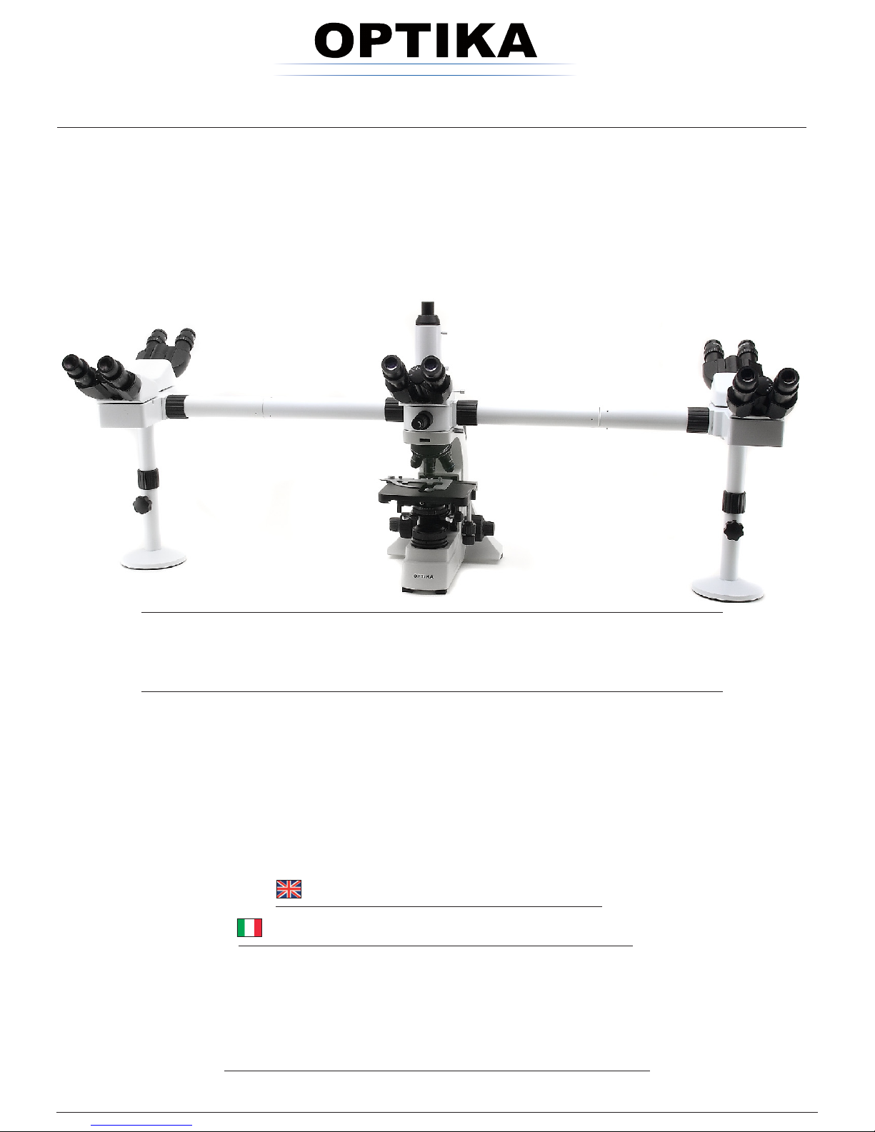
2.3 In order to use the green arrow which will be used asIn order to use the green arrow which will be used as
a pointer, it is mandatory to turn on the main switch
of the microscope body. Connect one terminal of the
provided cable into the back side of the splitter and the
other terminal into the connector placed of the upper
part of the microscope. (Fig. 2). Now use the pointer
position controller (1) or the pointer intensity controller
(2) to adapt to specific needs position and intensity of
the pointer.
Fig. 1
Pointer position controller (1)
Pointer intensity controller (2)
Fig. 2
Page 4
Fig. 6
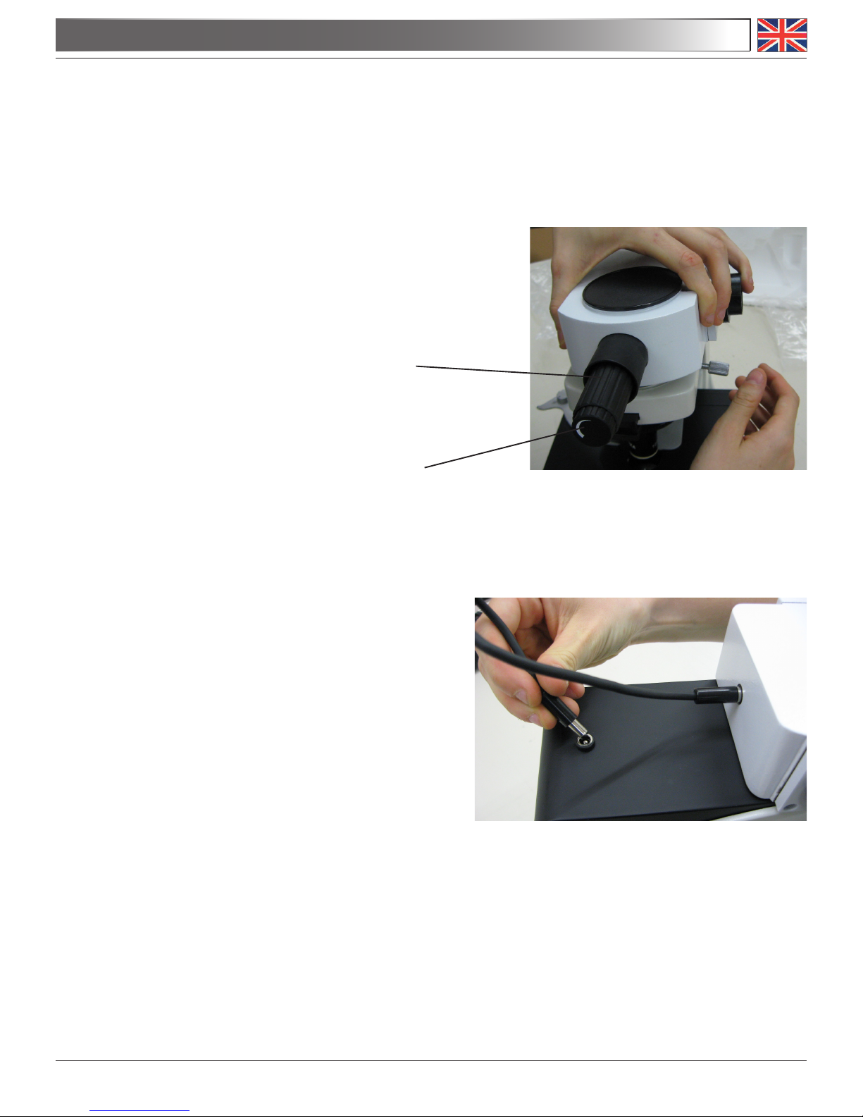
2.4 Begin to place the connection tubes on both sides of
the splitter attachment. Firmly screw the black ring
nut. (Fig. 3-4).
« Every connection is identified by a letter printed on
both sides of the connection. Make sure to match
the letters in order to correctly assemble the microscope..
2.5 Repeat the same procedure on the other side of the
splitter (in case of B-500Ti-5)
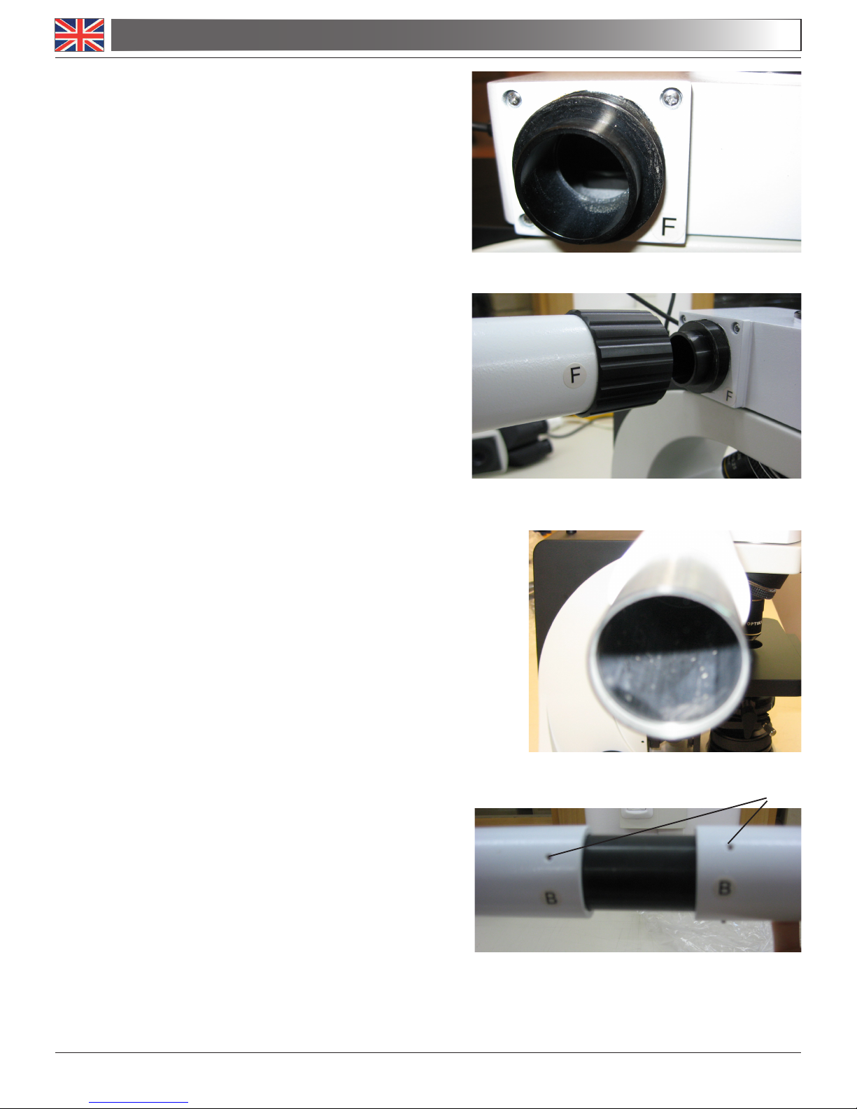
2.6 Insert the second part of the extension tube (Fig. 6).
« At the end of the first extension tube there is a lens
(Fig. 5). Make sure it is free from dirt, dust or other
contaminants before to proceed with the assembling of the second extension tube.
2.7 Fully insert the second extension tube in the right posi-
tion. Using the provided Allen wrench (small one) lock
the fixing screws (1) to block the extension tube (Fig.
6).
Fig. 3
Fig. 4
Fig. 5
(1)
2.0 UNPACKING AND ASSEMBLY
 Loading...