


OPTIKA MICROSCOPES - ITALY
www.optikamicroscopes.com - info@optikamicroscopes.com
Ver. 1.0.0
B-500 MET
OPERATION MANUAL
GUIDA UTENTE
MANUAL DE INSTRUCCIONES
BEDIENUNGSANLEITUNG

Page 2
INDEX
SAFETY GUIDELINES page 3
1.0 DESCRIPTION page 4
2.0 INTRODUCTION page 6
3.0 UNPACKING AND ASSEMBLY page 6
4.0 USING THE MICROSCOPE page 8
5.0 MAINTENANCE page 11
6.0 ELECTRICAL SPECIFICATIONS page 11
7.0 RECOVERY AND RECYCLING page 12
Page 3
SAFETY GUIDELINES
This microscope is a scientic precision instrument designed to last for many years with a minimum
of maintenance. It is built to high optical and mechanical standards and to withstand daily use.
Optika reminds you that this manual contains important information on safety and maintenance, and
that it must therefore be made accessible to the instrument users.
Optika declines any responsibility deriving from instrument uses that do not comply with this manual.
Safety guidelines
This manual contains important information and warnings regarding safety about installation,
use and maintenance of the microscope. Please read this manual carefully before using the
equipment. To ensure safe use, the user must read and follow all instructions in this manual.
OPTIKA products are designed for safe use in normal operating conditions. The equipment
and accessories described in the manual are manufactured and tested according to industry
standards for safety instrumentation laboratory. Misuse can cause personal injury or damage
to the instrument. Keep this manual at hand close to the instrument, for an easy consultation.
Electrical safety
Before connecting the power cord to wall outlet, ensure that your mains voltage for your
region corresponds to the voltage supply of the instrument, and that the illuminator’s switch
is in position OFF. The user must observe the safety regulations in force in his region. The
instrument is equipped with CE safety marking, in any case the user has full responsibility
concerning the safe use of that instrument.
Warning/Caution symbols used in this manual
The user should be aware of safety aspects when using the instrument. Warning or hazard
symbols are shown below. These symbols are used in this manual.
The instructions on this symbol to avoid possible severe personal injuries.
Warning of use; the incorrect operation on the instrument can cause damages
to the person or instrument.
Possibility of electric shock.
Attention: high temperature surfaces. Avoid direct contact.
Technical notes or usage tips.
Page 4
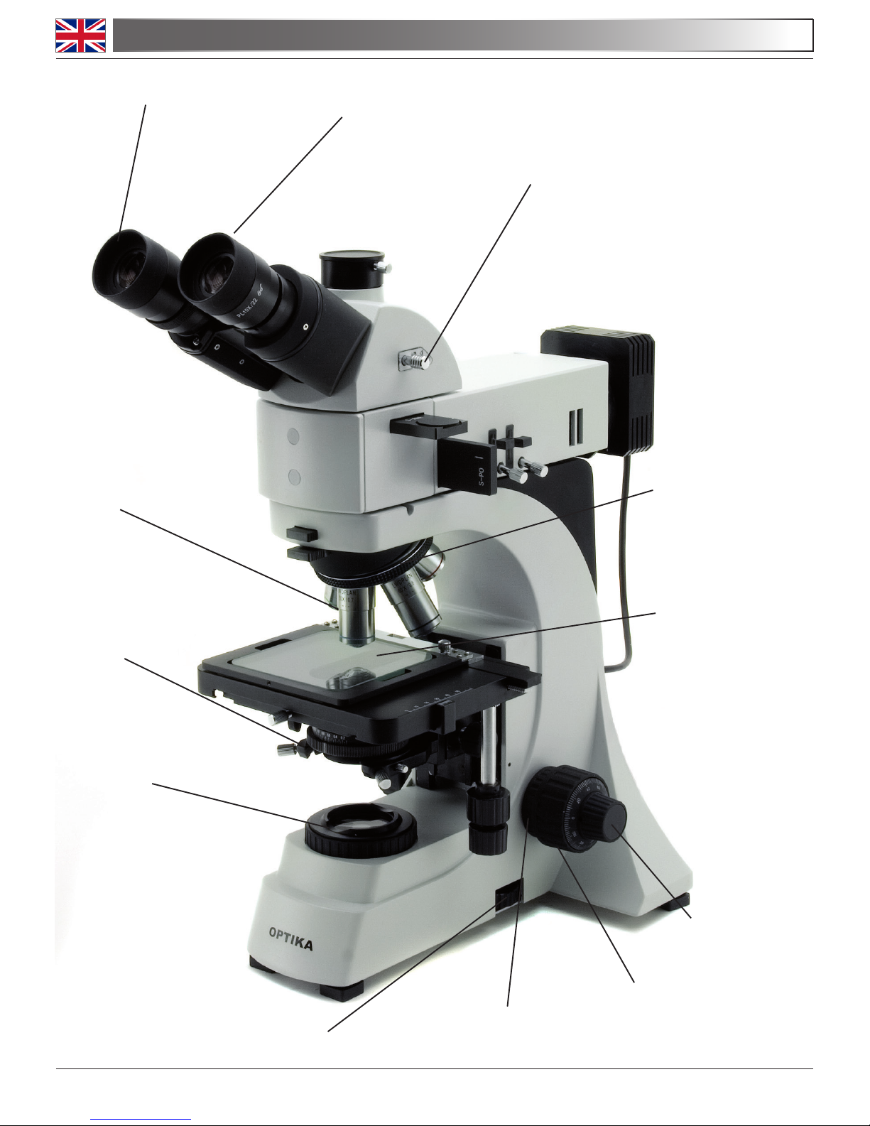
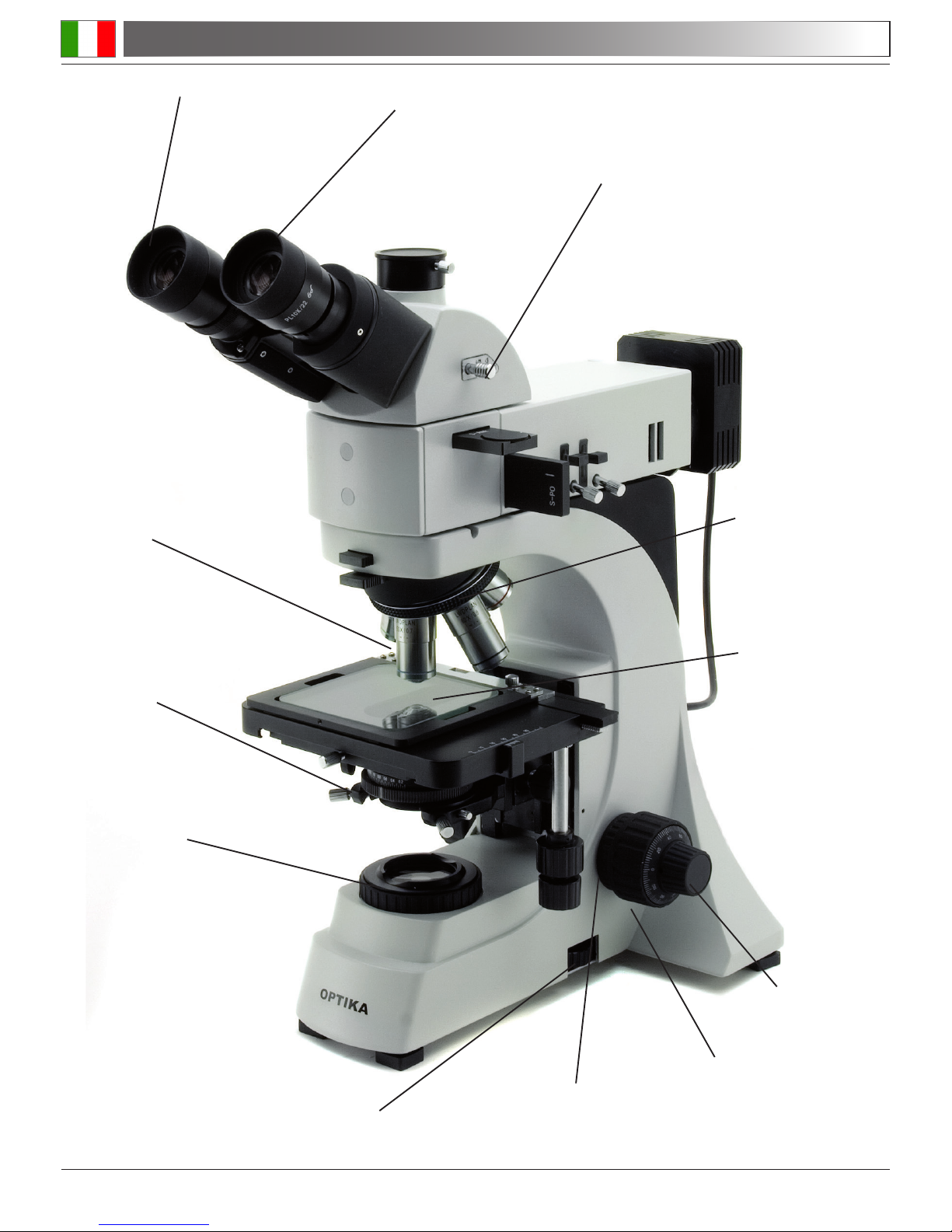
1.0 DESCRIPTION
Eyepiece
Dioptric adjustment ring
Photo Port selector
lever
Objectives
Iris diaphragm
Field diaphragm
Stage
Nosepiece
Fine focusing knob
Coarse focusing
knob
Tension adjustment
knob
Brighteld brightness adjustment knob (epillumination knob on the other side)
Page 5
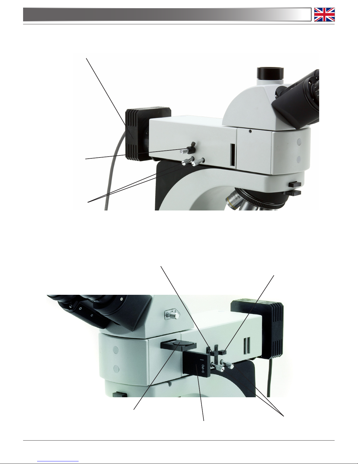
1.0 DESCRIPTION
White LED housing
Darkeld lever
Diaphragm centring
screws
Metallographic features
Field diaphragm
Aperture diaphragm
Analyzer lter (rotating)
Polarizer lter
Diaphragm centering
screws
Page 6
2.0 INTRODUCTION
This microscope is a scientic precision instrument designed to last for many years with a minimum of maintenance. It is built to high optical and mechanical standards and to withstand daily
classroom and laboratory use.
Optika reminds you that this manual contains important information on safety and maintenance,
and that it must therefore be made accessible to the instrument users.
Optika declines any responsibility deriving from instrument uses that do not comply with this manual.
3.1 The microscope is housed in a moulded Styrofoam container. Remove the tape from the
edge of the container and lift the top half of the container. Take some care to avoid that the
optical items (objectives and eyepieces) fall out and get damaged. Using both hands (one
around the arm and one around the base), lift the microscope from the container and put it
on a stable desk.
3.2 The objectives are located in individual protective vials. Remove the objectives from the vi-
als and insert them into the microscope nosepiece in the order from the lowest magnication
to the highest, in a clockwise direction from the rear.
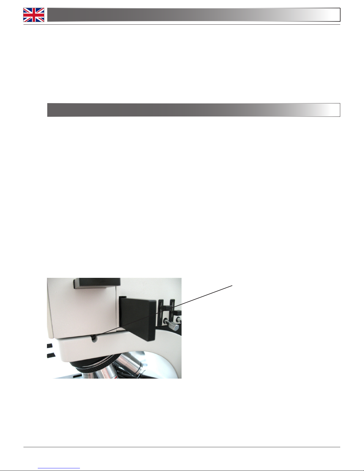
3.3 In a separate box you nd the metallographic attachment. Take it out and place it onto the
top of the microscope’s stand. Then lock it in position by turning the screw with the provided
allen wrench:
3.0 UNPACKING AND ASSEMBLY
Locking screw for the
attachment
Page 7
3.4 Place the observation head into the top of the attachment and tighten the lock-screw.
3.5 Insert the eyepieces into the eye tubes.
3.6 Insert polarizer and analyzer lters into their slots in the metallographic attachment.
3.7 Connect the power cable of the epillumination to the appropriate connector on the rear.
3.0 UNPACKING AND ASSEMBLY
Connect the mains plug into the socket at the base
Make sure, before you turn the illumination on, that the voltage selector is set to the mains
voltage for your region.
The power cord should be used only on network sockets equipped with adequate grounding.
Contact a technician to check the state of your electrical system. If there is no need to install
additional accessories, the instrument is now ready for use. Once positioned and installed
with the necessary components, the microscope is ready to be used. Your microscope is a
laboratory instrument designed to last. Handle it always carefully and avoid abrupt vibrations
or shocks. Always disconnect the power cable from the microscope when not in use for long
time, while you clean it or when you perform any maintenance.
AVOID DISASSEMBLING THE INSTRUMENT
Do not disassemble the instrument. This entails the cancellation of the warranty and may
cause malfunction.

Page 8
4.1 Adjust the observation head
Loosen the lock-screw, turn the observation head to a comfortable position for observation,
and then lock the lock-screw.
4.2 Place the specimen on the stage
Put the specimen on the mechanical stage (transparent glass plate). Ensure that the specimen is centred over the stage opening by adjusting the coaxial knobs of the stage.
Brighteld vision
4.3 Lamp settings
The microscope is tted with a 3.5W X-LED3 illuminator. Insert the plug of the cable into
the power socket and turn on the switch on the back of the main body. Turn the brightness
adjustment knob (on the right of the body) until you hear a “click”, meaning that the lamp is
on, then keep turning the knob to a brightness level suitable for observation.
4.4 Adjust interpupillary distance
Hold the right and left parts of the observation head by both hands and adjust the interpupillary distance by turning the two parts until one circle of light can be seen. After nishing
the interpupillary adjustment, turn the dioptric adjustment ring on the left eye tube to the “0”
position at the graduation line on the eyetube.
4.5 Focus and diopter adjustment
Loosen the focus-stop knob (near the left focus knob), rotate the coarse focusing knob to
bring the slide into focus with an objective with a low magnication, and then lock the focusstop knob. Adjust the ne focusing knob to get the image sharp and clear while observing
with your right eye, then turn the left dioptric adjustment ring to a sharp and clear image
also with the other eye. Turn the tension-adjust-knob (near the right focus knob) to get a
suitable tension for the focus system. When the image is in focus, turn the nosepiece to
choose the objective you need.
4.6 Condenser adjustment
Turn the condenser adjustment knob to move the condenser up or down for a clear and
uniform sample illumination. The two condenser-centring screws can be used to centre the
condenser.
4.7 Set the numerical aperture
Adjust the aperture of the iris diaphragm to set the numerical aperture of the illuminator,
thus controlling image contrast and resolution.
4.8 Field diaphragm
Adjust the eld diaphragm to align the system and to control stray light.
4.9 Additional lters
The chromatic correction lter (blue) can be inserted into the holder (just above the ring of
the eld diaphragm) for denition of specimen parts.
4.0 USING THE MICROSCOPE
Page 9
4.0 USING THE MICROSCOPE
4.10 Video capturing (optional)
B-500MET be connected to cameras via a photo/video adaptor, for photo and video capturing. Before taking a picture or lming video, if necessary, obscure with a dark cloth both the
camera viewnder and the eyepieces and pull out the light path selector lever. Please refer
to the adaptor and camera manuals for further details.
Epillumination vision (metallography)
4.11 Lamp settings
The metallographic attachment is tted with an high power white LED. Insert the plug of the
cable into the power socket and turn on the switch on the back of the main body. Turn the
brightness adjustment knob (on the left of the body) until you hear a “click”, meaning that
the LED is on, then keep turning the knob to a brightness level suitable for observation.
Please note: if no light comes out from the objective, check that both diaphragms on the
metallographic attachment are open (levers UP).
4.12 Adjust interpupillary distance
Hold the right and left parts of the observation head by both hands and adjust the interpupillary distance by turning the two parts until one circle of light can be seen. After nishing
the interpupillary adjustment, turn the dioptric adjustment ring on the left eye tube to the “0”
position at the graduation line on the eyetube.
4.13 Focus and diopter adjustment
Loosen the focus-stop knob (near the left focus knob), rotate the coarse focusing knob to
bring the slide into focus with an objective with a low magnication, and then lock the focusstop knob. Adjust the ne focusing knob to get the image sharp and clear while observing
with your right eye, then turn the left dioptric adjustment ring to a sharp and clear image
also with the other eye. Turn the tension-adjust-knob (near the right focus knob) to get a
suitable tension for the focus system. When the image is in focus, turn the nosepiece to
choose the objective you need.
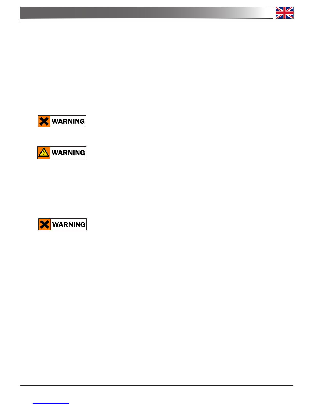
4.14 Field diaphragm
Adjust the eld diaphragm to control stray light. If you want to close the diaphragm, pull
down the lever:
Field diaphragm
lever
Field diaphragm
centering screw
Page 10
At the bottom of the lever, on both sides of the microscopes, there is a couple of screws that
can centre the eld diaphragm.
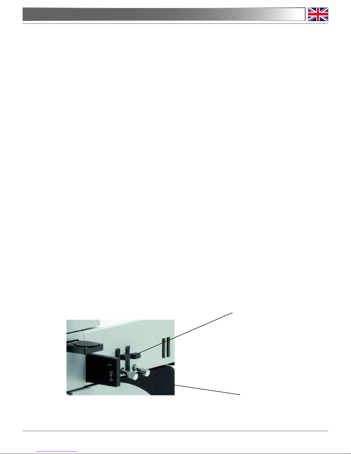
4.15 Set the numerical aperture
Adjust the aperture of the iris diaphragm to set the numerical aperture of the epilluminator,
thus controlling image contrast and resolution. If you want to close the diaphragm, pull down
the lever:
At the bottom of the lever, on both sides of the microscopes, there is a couple of screws that can
centre the aperture diaphragm.
4.16 Polarization analysis
Slightly pull outwards the polarizer lter (marked “S-PO”) to insert it into the optical path. Turn
the rotating disc of the analyzer lter: if the two lters are correctly inserted, you should nd a
position of the analyzer where no light is transmitted (“crossed polarizers” position).
4.17 Darkeld vision
After you focus the sample with the proper objective, slowly push the darkeld lever toward
the inside. Stop pushing as soon as you see a shadow covering your sample. In this manner you should obtain an oblique illumination that greatly enhances the reliefs and supercial
defects of your sample.
4.0 USING THE MICROSCOPE
Aperture diaphragm
lever
Aperture diaphragm
centering screw

Page 11
5.0 MAINTENANCE
5.1 Always think about
- The following environment is required: Indoor temperature: 0-40°C, Maximum relative humi
dity: 85 % (non condensing).
- Keep the microscope away from dust and shocks while in use.
- Turn off the light immediately after use.
- Use a soft lens tissue to clean the optics after use.
- Only if needed, use a cloth moistened with water and a mild detergent, rinsing with
water and drying immediately with a lint-free cloth.
- After use, cover the microscope with the included dust-cover, and keep it in a dry and clean
place.
5.2 Do not!
- Wipe the surface of any optical items with your hands. Fingerprints can damage the optics.
- Use solvents, neither on the microscope, nor on the optics.
- Disassemble objective or eyepieces to attempt to clean them.
- Mishandle or impose unnecessary force on the microscope.
- Clean the unit with volatile solvents or abrasive cleaners.
- Attempt to service the microscope yourself.
5.3 If you need to send the microscope to Optika for maintenance, please use the original packa-
ging.
Input Voltage: 90-240 Vac, 50/60 Hz
Brighteld Lamp: 3,5W X-LED
3
Epillumination: High power white LED
6.0 ELECTRICAL SPECIFICATIONS
Page 12
7.0 RECOVERY AND RECYCLING
Art.13 Dlsg 25 july 2005 N°151. “According to directives 2002/95/EC, 2002/96/EC and 2003/108/EC
relating to the reduction in the use of hazardous substances in electrical and electronic equipment
and waste disposal.”
The basket symbol on equipment or on its box indicates that the product at the end of its useful life
should be collected separately from other waste.
The separate collection of this equipment at the end of its lifetime is organized and managed by
the producer. The user will have to contact the manufacturer and follow the rules that he adopted
for end-of-life equipment collection. The collection of the equipment for recycling, treatment and
environmentally compatible disposal, helps to prevent possible adverse effects on the environment
and health and promotes reuse and/or recycling of materials of the equipment. Improper disposal
of the product involves the application of administrative penalties as provided by the laws in force.


Pagina 14
INDICAZIONI PER LA SICUREZZA pag 15
1.0 DESCRIZIONE pag. 16
2.0 INTRODUZIONE pag. 18
3.0 DISIMBALLAGGIO E INSTALLAZIONE DEL MICROSCOPIO pag. 18
4.0 UTILIZZO DEL MICROSCOPIO pag. 20
5.0 MANUTENZIONE DEL MICROSCOPIO pag. 23
6.0 SPECIFICHE ELETTRICHE pag. 23
7.0 MISURE ECOLOGICHE pag. 24
INDICE
Pagina 15
INDICAZIONI PER LA SICUREZZA
Il presente microscopio è uno strumento scientico di precisione studiato per durare molti anni con
una manutenzione minima, essendo costruito secondo i migliori standard ottici e meccanici e progettato per un utilizzo quotidiano.
Optika ricorda che il presente manuale contiene informazioni importanti per un uso sicuro e una
corretta manutenzione dello strumento. Esso deve quindi essere accessibile a chiunque lo utilizzi.
Optika declina ogni responsabilità derivante da un uso improprio dei suoi strumenti non indicato
dalla presente guida.
Avvertenze di sicurezza
Questo manuale contiene importanti informazioni e avvertenze riguardanti la sicurezza riguardo l’installazione, l’utilizzo e la manutenzione del microscopio. Si raccomanda di leggere
attentamente il manuale prima di qualsiasi utilizzo dello strumento. Per assicurare un utilizzo
sicuro l’utente deve leggere e seguire tutte le istruzioni poste nel presente manuale.
I prodotti OPTIKA sono studiati per un utilizzo sicuro in condizioni operative normali. Lo strumento e gli accessori descritti nel manuale sono realizzati e testati secondo standard industriali di sicurezza per strumentazione da laboratorio.
L’utilizzo non corretto può causare lesioni alla persona o danni allo strumento.
Mantenere questo manuale a portata di mano vicino allo strumento, per una facile consultazione.
Precauzioni di sicurezza elettrica
Prima di collegare il cavo di alimentazione alla presa di rete, assicurarsi che la tensione di
rete della vostra regione corrisponda alla tensione di alimentazione dello strumento, e che
l’interruttore dell’illuminatore sia in posizione spenta.
L’utente deve osservare la regolamentazione riguardante la sicurezza in vigore nel proprio
Stato. Lo strumento è dotato di marcatura di sicurezza CE, in ogni caso l’utente ha piena responsabilità riguardo all’utilizzo sicuro dello strumento stesso.
Simboli di avvertenza/pericolo usati nel manuale
L’utente deve essere a conoscenza degli aspetti legati alla sicurezza nel momento in cui
utilizza lo strumento. I simboli di avvertenza o pericolo sono indicati sotto. Tali simboli sono
utilizzati in questo manuale di istruzioni.
Seguire le istruzioni contrassegnate da questo simbolo per evitare possibili gravi danni alle persone.
Avvertimento di utilizzo; la non corretta operazione sullo strumento può causare
danni alla persona o allo strumento.
Possibilità di shock elettrico.
Attenzione: superci ad elevata temperatura. Evitare il contatto diretto.
Note tecniche o consigli di utilizzo.
Pagina 16
Oculare
Anello di compensazione
diottrica
Levetta di selezione
Uscita Foto-Video
Obiettivi
Diaframma di
apertura
Diaframma
di campo
Tavolo
Revolver
Manopola focus
micrometrico
Manopola focus
macrometrico
Ghiera di regolazio-
ne tensione
Manopola di regolazione intensità campo chiaro
(manopola per l’epilluminazione sull’altro lato)
1.0 DESCRIZIONE

Pagina 17
1.0 DESCRIZIONE
Alloggiamento LED bianco
Levetta per campo
scuro
Viti di centraggio
diaframmi
Caratteristiche metallograche
Diaframma di
campo
Diaframma di apertura
Filtro analizzatore
(ruotabile)
Filtro polarizzatore
Viti di centraggio
diaframmi

Pagina 18
2.0 INTRODUZIONE
Il presente microscopio è uno strumento scientico di precisione studiato per durare molti anni
con una manutenzione minima, essendo costruito secondo i migliori standard ottici e meccanici e
progettato per un utilizzo quotidiano in aula e in laboratorio.
Optika ricorda che il presente manuale contiene informazioni importanti per un uso sicuro e una
corretta manutenzione dello strumento. Esso deve quindi essere accessibile a chiunque lo utilizzi.
Optika declina ogni responsabilità derivante da un uso improprio dei suoi strumenti non contemplato dalla presente guida.
3.1 Il microscopio si trova in un imballo in polistirolo espanso stampato. Dopo aver aperto la
scatola, sollevare la parte superiore dell’imballo. Fare attenzione a non far cadere e danneggiare le componenti ottiche (obiettivi e oculari). Estrarre il microscopio dal suo imballo
con entrambe le mani (una sosterrà il braccio e l’altra la base) e appoggiarlo su un piano
stabile.
3.2 Gli obiettivi sono confezionati singolarmente in custodie di protezione. Togliere gli obiettivi
dalle loro custodie e inserirli nel revolver portaobiettivi dall’obiettivo con il minore potere di
ingrandimento a quello con il maggiore, in direzione oraria partendo dalla parte posteriore.
3.3 In un imballo separato trovate l’attacco metallurgico. Estrarlo e posizionarlo sulla sommità
dello stativo del microscopio. Quindi ssarlo in posizione ruotante la vite con le brugole in
dotazione.
3.0 DISIMBALLAGGIO E INSTALLAZIONE DEL MICROSCOPIO
Vite di ssaggio dell’attacco
metallograco

Pagina 19
3.4 Posizionare la testa ottica sulla sommità dell’attacco metallograco e stringere la relativa
vite di ssaggio (sul lato sinistro).
3.5 Inserire gli oculari nei tubi della testa ottica.
3.6 Inserire i ltri polarizzatore e analizzatore nei rispettivi slot nell’attacco metallograco
(vedi immagine nella sezione Descrizione).
3.7 Connettere il cavo di alimentazione dell’epilluminatore al relativo connettore posto sul retro
del microscopio:
3.0 DISIMBALLAGGIO E INSTALLAZIONE DEL MICROSCOPIO
Connettere il cavo di alimentazione nella presa posta nella base dello stativo.
Assicurarsi, prima dell’accensione, che il selettore del voltaggio sia impostato sulla tensione
di rete della vostra regione.
Il cavo di alimentazione deve essere utilizzato solo su prese di rete dotate di adeguata messa
a terra.
Contattare un vostro tecnico per assicurarsi sullo stato dell’impianto elettrico. Se non vi è
necessità di installare altri accessori, lo strumento è ora pronto per l’utilizzo. Una volta posizionato e installato con i necessari componenti, il microscopio è pronto per l’utilizzo. Il vostro
microscopio è uno strumento da laboratorio progettato per durare a lungo. Maneggiatelo
sempre con cura ed abitate brusche vibrazioni o colpi. Scollegare sempre il cavo di alimentazione dal microscopio quando non viene utilizzato per lunghi tempi, mentre lo si pulisce o
quando si esegue una qualsiasi manutenzione.
EVITARE DI SMONTARE LO STRUMENTO
Non disassemblare lo strumento. Questo comporta l’annullamento della garanzia e potrebbe
causare malfunzionamenti.

Pagina 20
4.1 Regolazione della testa ottica
Allentare la vite di serraggio, ruotare la testata no a trovare una posizione comoda per
l’osservazione e quindi avvitarla nuovamente.
4.2 Posizionamento del campione sul tavolino
Posizionare il campione sul tavolino meccanico (sulla lastra di vetro di supporto).
Assicurarsi che il campione sia centrato regolando la posizione con le manopole coassiali.
Visione in campo chiaro
4.3 Regolazione della lampada
Il microscopio è dotato di un illuminatore X-LED3 da 3.5W. Inserire la spina del cavo di alimentazione in una presa di rete e premere il pulsante di accensione posto sul retro. Ruotare quindi la manopola di regolazione dell’intensità (sulla destra dello stativo, in basso), no
ad udire un “click” indicante l’accensione della lampada; continuare a ruotare la manopola
no ad ottenere un livello di luminosità sufciente.
4.4 Regolazione della distanza interpupillare
Regolare la distanza interpupillare dei portaoculari sulla testata no ad ottenere la visione
di un unico campo luminoso circolare tenendo ferme le parti destra e sinistra della testata di
osservazione. Terminata la regolazione, ruotare l’anello di compensazione diottrica sull’oculare sinistro no a raggiungere lo “0” (zero) sulla scala graduata.
4.5 Regolazione della messa a fuoco e compensazione diottrica
Sbloccare la manopola di ne corsa della messa a fuoco, ruotare la manopola di messa a
fuoco macrometrica per focalizzare il vetrino con un obiettivo con basso potere di ingrandimento, quindi bloccare di nuovo la manopola. Regolare la manopola di messa a fuoco
micrometrica no ad ottenere un’immagine chiara e denita osservando con l’occhio destro,
quindi ripetere l’operazione con l’anello di compensazione diottrica sinistro e l’occhio sinistro. Con la manopola di regolazione della tensione impostare la tensione migliore per la
messa a fuoco. Quando l’immagine è a fuoco, scegliere l’obiettivo desiderato sul revolver
portaobiettivi.
4.6 Regolazione del condensatore
Alzare o abbassare il condensatore mediante l’apposita manopola per ottenere un’illuminazione chiara e uniforme dell’oggetto. Per centrare il condensatore servirsi delle due viti di
centraggio.
4.7 Impostazione della copertura del diaframma
Regolare l’apertura del diaframma ad iride per impostare l’apertura numerica di illuminazione, per controllare contrasto d’immagine e risoluzione.
4.8 Diaframma di campo
Regolare l’iride del diaframma di campo per controllare l’allineamento del sistema e ridurre
la luce diffusa.
4.9 Filtro addizionale
Il ltro di correzione cromatica (blu) può essere inserito nell’apposito supporto (direttamente
sopra la ghiera del diaframma di campo).
4.0 UTILIZZO DEL MICROSCOPIO

Pagina 21
4.0 UTILIZZO DEL MICROSCOPIO
4.10 Acquisizione video e foto (opzionale)
La serie B-500MET è collegabile a una telecamera con un adattatore per acquisire foto e
video. Prima di procedere all’acquisizione di immagini video/foto, se necessario, si consiglia
di oscurare con un panno scuro sia il mirino della macchina fotograca/videocamera che gli
oculari e di staccare la levetta di selezione del percorso ottico. Per ulteriori dettagli si rimanda ai manuali degli adattatori.
Visione in epilluminazione (metallograa)
4.11 Impostazione dell’illuminatore
L’attacco metallograco è dotato di un illuminatore a LED bianco di alta potenza. Inserire
la spina del cavo di alimentazione in una presa di rete e premere il pulsante di accensione
posto sul retro. Ruotare quindi la manopola di regolazione dell’intensità (sulla sinistra dello
stativo, in basso), no ad udire un “click” indicante l’accensione del LED; continuare a ruotare la manopola no ad ottenere un livello di luminosità sufciente.
Notare: se dall’obiettivo non esce alcuna luce, assicurarsi che entrambi i diaframmi dell’attacco metallograco siano aperti (levette in posizione ALTA).
4.12 Regolazione della distanza interpupillare
Regolare la distanza interpupillare dei portaoculari sulla testata no ad ottenere la visione
di un unico campo luminoso circolare tenendo ferme le parti destra e sinistra della testata di
osservazione. Terminata la regolazione, ruotare l’anello di compensazione diottrica sull’oculare sinistro no a raggiungere lo “0” (zero) sulla scala graduata.
4.13 Regolazione della messa a fuoco e compensazione diottrica
Sbloccare la manopola di ne corsa della messa a fuoco, ruotare la manopola di messa a
fuoco macrometrica per focalizzare il vetrino con un obiettivo con basso potere di ingrandimento, quindi bloccare di nuovo la manopola. Regolare la manopola di messa a fuoco
micrometrica no ad ottenere un’immagine chiara e denita osservando con l’occhio destro,
quindi ripetere l’operazione con l’anello di compensazione diottrica sinistro e l’occhio sinistro. Con la manopola di regolazione della tensione impostare la tensione migliore per la
messa a fuoco. Quando l’immagine è a fuoco, scegliere l’obiettivo desiderato sul revolver
portaobiettivi.
4.14 Diaframma di campo
Regolare il diaframma di campo per ridurre la luce diffusa. Se si desidera chiudere il diaframma, spingere verso il basso la levetta:
Levetta del diaframma di campo
Vite di centraggio
del diaframma di
campo

Pagina 22
4.0 UTILIZZO DEL MICROSCOPIO
Levetta del diaframma di apertura
Vite di centraggio
del diaframma di
apertura
Sotto la levetta, su entrambi i lati dell’attacco, c’è una coppia di viti tramite le quali è possibile
centrare il diaframma.
4.15 Impostare l’apertura numerica
Regolare l’apertura del diaframma ad iride per impostare l’apertura numerica dell’epillumi-
natore, per variare quindi il contrasto di immagine e la risoluzione. Se si desidera chiudere il
diaframma, spingere verso il basso la levetta:
Sotto la levetta, su entrambi i lati dell’attacco, c’è una coppia di viti tramite le quali è possibile centrare il diaframma.
4.16 Analisi in polarizzazione
Tirare con delicatezza verso l’esterno il ltro polarizzatore (marcato “S-PO”) per inserirlo nel
percorso ottico. Quindi ruotare il disco posto sul ltro analizzatore: se i due ltri sono inseriti
correttamente, dovreste trovare una posizione in cui nessuna luce viene trasmessa (posizione con “polarizzatori incrociati).
4.17 Visione in campo scuro semplicato
Dopo aver messo a fuoco il campione con l’obiettivo desiderato, spingere lentamente verso
l’interno la levetta per campo scuro (vedere immagine nella sezione Descrizione). Fermarsi
non appena un’ombra inizia ad oscurare eccessivamente il campione. In questo modo si
ottiene una illuminazione obliqua che mette in risalto i rilievi e i difetti superciali del vostro
oggetto.

Pagina 23
5.0 MANUTENZIONE
5.1 Da ricordare:
- Ambiente di lavoro con temperatura interna: 0-40°C.
Umidità relativa massima: 85% (in assenza di condensa).
- Durante l’uso proteggere il microscopio da polvere e urti.
- Spegnere la luce immediatamente dopo l’uso.
- Dopo l’uso pulire le ottiche con un apposito panno morbido.
- Solo se necessario, servirsi di un panno inumidito con acqua e un detersivo neutro, risciac
quando accuratamente con acqua e asciugando immediatamente con un panno non
slacciato.
- Dopo l’uso coprire il microscopio con la custodia antipolvere in dotazione e tenere in un
luogo asciutto e pulito.
5.2 Da evitare:
- Non stronare la supercie di nessun componente ottico con le mani perché le
impronte digitali possono danneggiare le ottiche.
- Non utilizzare solventi né sul microscopio né sulle ottiche.
- Non smontare gli obiettivi o gli oculari per cercare di pulirli.
- Maneggiare con cura e non adoperare inutile forza sul microscopio.
- Non pulire lo strumento con solventi volatili o agenti pulenti abrasivi.
- Non cercare di provvedere da soli alla manutenzione.
5.3 Si prega di utilizzare l’imballaggio originale nel caso in cui fosse necessario rispedire il micro-
scopio alla ditta Optika per la manutenzione.
Alimentazione: 90-240Vac, 50/60 Hz
Lampada campo chiaro: 3,5W X-LED
3
Epilluminazione: LED bianco alta potenza
6.0 SPECIFICHE ELETTRICHE

Pagina 24
Ai sensi dell’articolo 13 del decreto legislativo 25 luglio 2005 n°151. “Attuazione delle direttive
2002/95/CE, 2002/96/CE e 2003/108/CE, relative alla riduzione dell’uso di sostanze pericolose nelle
apparecchiature elettriche ed elettroniche, nonché allo smaltimento dei riuti”.
Il simbolo del cassonetto riportato sulla apparecchiatura o sulla sua confezione indica che il prodotto alla ne della propria vita utile deve essere raccolto separatamente degli altri riuti. La raccolta
differenziata della presente apparecchiatura giunta a ne vita è organizzata e gestita dal produttore.
L’utente che vorrà disfarsi della presente apparecchiatura dovrà quindi contattare il produttore e
seguire il sistema che questo ha adottato per consentire la raccolta separata dell’apparecchiatura
giunta a ne vita.
L’adeguata raccolta differenziata per l’avvio successivo della apparecchiatura dismessa al riciclaggio, al trattamento e allo smaltimento ambientalmente compatibile contribuisce ad evitare possibili
effetti negativi sull’ambiente e sulla salute e favorisce il reimpiego e/o riciclo dei materiali di cui è
composta l’apparecchiatura.
Lo smaltimento abusivo del prodotto da parte del detentore comporta l’applicazione delle sanzioni
amministrative previste dalla normativa vigente.
7.0 MISURE ECOLOGICHE

Pagina 25

Página 26
NORMAS DE SEGURIDAD pag. 27
1.0 DESCRIPCIÓN pag. 28
2.0 INTRODUCCIÓN pag. 30
3.0 DESEMBALAJE E INSTALACIÓN DEL MICROSCOPIO pag. 30
4.0 UTILIZACIÓN DEL MICROSCOPIO pag. 32
5.0 MANTENIMIENTO DEL MICROSCOPIO pag. 35
6.0 ESPECIFICACIONES ELÉCTRICAS pag. 35
7.0 MEDIDAS ECOLÓGICAS pag. 36
INDICE

Página 27
El presente microscopio es un instrumento cientíco de precisión proyectado para durar muchos
años con un mínimo nivel de mantenimiento. Para su construcción se han utilizado elementos ópticos y mecánicos de elevada calidad que lo convierten en el instrumento ideal para ser utilizado a
diario en las aulas y en el laboratorio.
Optika avisa que esta guía contiene importante información sobre la seguridad y el mantenimiento
del producto y por lo tanto debe ser accesible a todos aquellos que utilizan dicho instrumento.
Optika declina cualquier responsabilidad derivada de un uso inapropiado del presente instrumento
no contemplado en la presente guía.
Advertencias de seguridad
Este manual incluye importante información y normas sobre la seguridad de instalación,
utilización y mantenimiento del microscopio. Se ruega leer atentamente el manual antes de
utilizar el instrumento. Para una utilización segura, el usuario debe leer y seguir atentamente
todas la instrucciones del manual.
Los productos OPTIKA han sido diseñados para ser utilizados en condiciones normales de
trabajo. El instrumento y los accesorios descritos en el manual han sido realizados y testados
según las normas industriales de seguridad para instrumentación de laboratorio.
Una utilización inadecuada podría dañar el instrumento o provocar lesiones al usuario.
Mantener el presente manual cerca del instrumento para facilitar su consulta.
Normas de seguridad sobre el sistema eléctrico
Antes de conectar el microscopio a la toma de corriente, asegurarse que la tensión de entrada del lugar donde se usa coincide con la tensión de utilización del microscopio y que el
interruptor del iluminador esté en la posición off.
El usuario debe consultar las normas de seguridad de su país. El instrumento incluye
una etiqueta de seguridad CE. No obstante estas pautas, el usuario debería utilizar el microscopio en función de sus necesidades pero con un mínimo de responsabilidad y seguridad.
Símbolos de advertencia/peligro utilizados en el presente manual
El usuario debe conocer las indicaciones relacionadas con la seguridad cuando utiliza el microscopio. A continuación se indican los símbolos de advertencia o peligro. Dichos símbolos
se han utilizado en este manual de instrucciones.
Seguir las instrucciones indicadas para evitar posibles daños severos al
usuario.
Advertencia de utilización; la utilización inadecuada del instrumento podría
dañar el instrumento o provocar daños al usuario.
Posibilidad de descarga eléctrica.
Atención: supercie de elevada temperatura. Evitar el contacto directo.
Notas técnicas o consejos de utilización.
NORMAS DE SEGURIDAD

Página 28
1.0 DESCRIPCIÓN
Ocular
Anillo de compensación
dióptrica
Tornillo de selección
Salida Foto-Video
Objetivos
Diafragma de
apertura
Diafragma de
campo
Platina
porta-preparados
Revólver
Mando del enfoque
macrométrico
Mando del enfoque
micrométrico
Mando de regulación
de la tensión
Mando de regulación de la intensidad en campo
claro (mando para la epi-iluminación situado en el
lado opuesto)

Página 29
1.0 DESCRIPCIÓN
Soporte porta LED blanco
Características metalográcas
Diafragma de
campo
Diafragma de apertura
Filtro analizador
(giratorio)
Filtro polarizador
Tornillos de centrado
de los diafragmas
Palanca para
campo oscuro
Tornillos de
centrado de los
diafragmas

Página 30
2.0 INTRODUCCIÓN
Este microscopio es un instrumento cientíco de precisión proyectado para durar muchos años
con un mínimo nivel de mantenimiento. Para su construcción se han utilizado elementos ópticos y
mecánicos de elevada calidad que lo convierten en el instrumento ideal para la utilización diaria en
las aulas y en el laboratorio.
Optika avisa que esta guía contiene importante información sobre la seguridad y el mantenimiento del producto y por lo tanto debe ser accesible a todos aquellos que utilizan dicho instrumento.
Optika declina cualquier responsabilidad derivada del uso inapropiado del presente instrumento no
contemplado en la presente guía.
3.1 El microscopio se entrega con un embalaje de poliestireno. Después de abrir el embalaje,
abrir la parte superior del mismo. Prestar atención para evitar dañar los componentes ópticos
(objetivos y oculares) y para evitar que el instrumento se caiga. Extraer el microscopio de su
embalaje con ambas manos (con una mano sostener el brazo y con la otra la base) y apoyarlo en una supercie estable.
3.2 Los objetivos se presentan en estuches individuales especiales para su protección. Extraer
los objetivos y jarlas mediante rosca en el revólver portaobjetivos iniciando por la parte
posterior y girando en sentido horario. Empezar por el objetivo con menor poder de aumentos
para terminar con el de mayor aumentos.
3.3 El suplemento metalúrgico se presenta en un embalaje separado. Extraerlo y situarlo en la
parte superior del soporte del microscopio. Fijarlo en la posición giratoria utilizando las llaves
Allen suministradas.
3.0 DESEMBALAJE E INSTALACIÓN DEL MICROSCOPIO
Tornillos de jación de la unión
metalográca

Página 31
3.4 Situar el cabezal de observación encima del suplemento metalográco y estrechar el corres
pondiente tornillo de jación (situado a la izquierda).
3.5 Introducir los oculares en los tubos portaoculares del cabezal óptico.
3.6 Introducir el ltro polarizador y analizador en sus respectivas hendiduras del suplemento
metalográco (ver imagen en el apartado descripción).
3.7 Conectar el cable de alimentación del epi-iluminador en su correspondiente conector situado
en el reverso del microscopio:
3.0 DISIMBALLAGGIO E INSTALLAZIONE DEL MICROSCOPIO
Introducir el cable de alimentación en la toma situada en la base del microscopio.
Antes de encender el microscopio, asegurarse que el selector del voltaje se sitúe en la ten-
sión de red correspondiente a su país.
El cable de alimentación se debe utilizar solamente en tomas eléctricas con toma a tierra.
Consultar un técnico para asegurarse del estado de la red eléctrica. Después de haber situado e instalado el microscopio con los componentes necesarios, estará listo para su utilización. El microscopio es un instrumento de laboratorio proyectado para durar mucho tiempo.
Manejarlo siempre con mucha precaución, evitando las vibraciones bruscas y los golpes.
Desconectar siempre el cable de alimentación del microscopio cuando no se utiliza durante
un largo periodo de tiempo, mientras se limpia o cuando se realiza cualquier trabajo de mantenimiento.
NO DESMONTAR EL MICROSCOPIO
No desmontar el microscopio para evitar anular la garantía y provocar el funcionamiento
incorrecto.

Página 32
4.1 Regulación del cabezal de observación
Aojar el tornillo de ajuste, girar el cabezal hasta obtener una posición cómoda de
observación y por último estrecharlo de nuevo.
4.2 Colocación de la muestra en la platina portapreparados
Situar la muestra en la platina (en la placa de soporte de vidrio).
Asegurarse que la muestra se sitúe en el centro del campo de observación regulando su
posición con los mandos coaxiales.
Observación en campo claro
4.3 Regulación de la luz
El microscopio incluye un iluminador eléctrico X-LED3 3,5W. Introducir el enchufe del
cable en la toma de alimentación y pulsar el botón de puesta en marcha situado en la parte
posterior del soporte. Girar el mando de regulación de la luminosidad (situado en la parte
inferior derecha del soporte) hasta que se escuche un “click” que indica la puesta en marcha
de la lámpara. Seguir girando el mando hasta obtener un nivel de luminosidad suciente.
4.4 Regulación de la distancia interpupilar
Regular la distancia interpupilar de los tubos oculares del cabezal hasta obtener la visión de un único campo luminoso circular manteniendo rmes los lados derecho e izquierdo del cabezal de observación. Terminada la regulación, girar el anillo de compensación dióptrica del ocular izquierdo hasta alcanzar el “0” (cero) en la escala graduada.
4.5 Regulación del enfoque y compensación dióptrica
Extraer el tornillo que ja el mando de apertura del enfoque y aojar el mando. Girar el
mando de enfoque micrométrico para enfocar el preparado con un objetivo de bajo
poder de aumentos, después bloquear de nuevo el mando. Observando con el ojo
derecho, regular el mando de enfoque micrométrico para obtener una imagen clara y denida.
Repetir la misma operación con el ojo y el mando izquierdo. Girando el mando de
regulación de la tensión regular la tensión mas adecuada para el enfoque. Cuando la
imagen esté enfocada, seleccionar el objetivo deseado en el revólver portaobjetivos.
4.6 Regulación del condensador
Subir o bajar el condensador utilizando el correspondiente mando para obtener una
iluminación clara y uniforme del objeto. Para centrar el condensador utilizar los dos tornillos
de centrado.
4.7 Selección de la apertura numérica
Regular la apertura del diafragma iris para seleccionar la apertura numérica del iluminador
y controlar de esta manera el contraste de la imagen y la resolución.
4.8 Diafragma de campo
Regular el diafragma de campo para alinear el sistema y reducir la luz difusa.
4.9 Filtros adicionales
Se puede introducir en el correspondiente soporte (directamente encima del anillo del
diafragma de campo) el ltro con corrección cromática (azul).
4.0 UTILIZACIÓN DEL MICROSCOPIO

Página 33
4.0 UTILIZACIÓN DEL MICROSCOPIO
4.10 Adquisición de video/foto
Es posible conectar al modelo B-500MET una tele cámara, utilizando un adaptador, para
adquirir fotos y videos. Si fuera necesario, antes de adquirir las imágenes video/foto, se
aconseja oscurecer con un paño oscuro el visor de la cámara fotográca/videocámara y los
oculares y desconectar el mando de selección del recorrido óptico. Para mayor información,
consultar el manual de los adaptadores.
Observación en epi-iluminación (metalografía)
4.11 Conguración del iluminador
El suplemento metalográco incluye un iluminador LED de alta potencia. Introducir el
enchufe del cable en la toma de alimentación y pulsar el botón de puesta en marcha situado
en la parte posterior del soporte. Girar el mando de regulación de la luminosidad (situado en
la parte inferior derecha del soporte) hasta que se escuche un “click” que indica la puesta en
marcha del LED. Seguir girando el mando hasta obtener el nivel suciente de luminosidad.
Nota: si no sale luz del objetivo, comprobar que los dos diafragmas del suplemento
metalográco estén abiertos (palanca en posición ALTA).
4.12 Regulación de la distancia interpupilar
Regular la distancia interpupilar de los tubos oculares del cabezal hasta obtener la visión
de un único campo luminoso circular manteniendo rmes los lados derecho e izquierdo del
cabezal de observación. Terminada la regulación, girar el anillos de compensación dióptrica
del ocular izquierdo hasta alcanzar el “0” (cero) en la escala graduada.
4.13 Regulación del enfoque y compensación dióptrica
Extraer el tornillo que ja el mando de apertura del enfoque y aojar el mando. Girar el
mando de enfoque micrométrico para enfocar el preparado con un objetivo de bajo
poder de aumentos, después bloquear de nuevo el mando. Observando con el ojo
derecho, regular el mando de enfoque micrométrico para obtener una imagen clara y denida.
Repetir la misma operación con el ojo y el mando izquierdo. Girando el mando de
regulación de la tensión regular la tensión mas adecuada para el enfoque. Cuando la
imagen esté enfocada, seleccionar el objetivo deseado en el revólver portaobjetivos.
4.14 Diafragma de campo
Regular el diafragma de campo para reducir la luz difusa. Si se desea cerrar el diafragma,
bajar la palanca:
Palanca del
diafragma de
campo
Vite di centraggio
del diaframma di
campo

Página 34
4.0 UTILIZACIÓN DEL MICROSCOPIO
Debajo de la palanca, a ambos lados del suplemento, hay una pareja de tornillos a través de
los cuales es posible centrar el diafragma.
4.15 Selección de la apertura numérica
Regular la apertura del diafragma iris para seleccionar la apertura numérica del
epi-iluminador y para variar por lo tanto, el contraste de la imagen y la resolución. Si se desea
cerrar el diafragma, bajar la palanca:
Debajo de la palanca, a ambos lados del suplemento, hay una pareja de tornillos con loas cuales es
posible centrar el diafragma.
4.16 Análisis en polarización
Tirar con delicadeza hacia el exterior el ltro polarizador (“S-PO”) para introducirlo en el
recorrido óptico. Girar el disco situado en el ltro analizador: si los dos ltros están
introducidos correctamente, se encontrará la posición donde no se transmite ninguna luz
(posición con “polarizadores cruzados”).
4.17 Observación en campo oscuro simplicada
Después de haber enfocado la muestra con el objetivo deseado, pulsar hacia el interno la
palanca para campo oscuro (ver imagen en el apartado Descripción). Pararse cuando una
sombra empieza a oscurecer excesivamente la muestra. De esta manera se obtiene una
iluminación oblicua que resalta los relieves y los defectos superciales del objeto.
Palanca del
diafragma de
apertura
Tornillos de centrado
del diafragma de
apertura

Página 35
5.0 MANTENIMIENTO DEL MICROSCOPIO
5.1 Recordar:
- Ambiente de trabajo recomendado: Temperatura interna: 0-40°C.
Humedad relativa máxima: 85 % (en ausencia de condensación).
- Durante el uso proteger el microscopio de polvo e impactos.
- Apagar la luz inmediatamente después de haber utilizado el microscopio.
- Después del uso limpiar las ópticas con un paño suave.
- Sólo si fuera necesario, limpiar con un paño humedecido en agua y detergente neutro
y secar delicadamente e inmediatamente con un paño que no esté deshilachado.
- Después de haber utilizado el microscopio, cubrirlo con su correspondiente funda antipolvo
y mantenerlo en un ambiente limpio y seco.
5.2 Evitar:
- No frotar la supercie de ningún componente óptico con las manos. Las huellas digitales
pueden dañar las ópticas.
- No utilizar disolventes ni en el microscopio ni en las ópticas.
- No desmontar los objetivos o los oculares para intentar limpiarlos.
- Manejar con cuidado el microscopio evitando usar una fuerza mayor de la necesaria.
- No limpiar el instrumento con disolventes volátiles o detergentes abrasivos.
- No reparar el microscopio por su cuenta.
5.3 Se ruega utilizar el embalaje original si fuera necesario enviar el microscopio a la empresa
Optika para el mantenimiento.
Alimentación : 90-240 Vac, 50/60 Hz
Lámpara: 3,5W X-LED
3
Epi-iluminación: LED blanco de alta potencia
6.0 ESPECIFICACIONES ELÉCTRICAS

Página 36
7.0 MEDIDAS ECOLÓGICAS
En conformidad con el Art. 13 del D.L. de 25 julio 2005 n°151.Actuación de las Directivas 2002/95/
CE, 2002/96/CE y 2003/108/CE, relativas a la reducción del uso de sustancias peligrosas en la instrumentación eléctrica y electrónica y a la eliminación de residuos.
El símbolo del contenedor que se muestra en la instrumentación o en su embalaje indica que el
producto cuando alcanzará el nal de su vida útil se deberá recoger de forma separada del resto
de residuos. La gestión de la recogida selectiva de la presente instrumentación será llevada a cabo
por el fabricante.Por lo tanto, el usuario que desee eliminar la presente instrumentación tendrá
que ponerse en contacto con el fabricante y seguir el sistema que éste ha adoptado para permitir
la recogida selectiva de la instrumentación. La correcta recogida selectiva de la instrumentación
para su posterior reciclaje, tratamiento y eliminación compatible con el ambiente contribuye a evitar
posibles efectos negativos al ambiente y a la salud y favorece su reutilización y/o reciclado de los
componentes de la instrumentación.
La eliminación del producto de forma abusiva por parte del usuario implicaría la aplicación de las
sanciones administrativas previstas en la normativa vigente.


Seite 38
VORSICHTSMASSNAHM Seite 39
1.0 BESCHREIBUNG Seite 40
2.0 EINLEITUNG Seite 42
3.0 AUSPACKEN UND MONTAGE Seite 42
4.0 VERWENDUNG DES MIKROSKOPS Seite 44
5.0 WARTUNG Seite 47
6.0 ELEKTRISCHE SPEZIFIKATIONEN Seite 47
7.0 WIEDERVERWERTUNG Seite 48
INHALT

Seite 39
VORSICHTSMASSNAHMEN
Dieses Mikroskop ist ein wissenschaftliches Präzisionsgerät, es wurde entwickelt für eine jahrelange Verwendung bei einer minimalen Wartung. Dieses Gerät wurde nach den höchsten optischen
und mechanischen Standards und zum täglichen Gebrauch hergestellt.
Diese Bedienungsanleitung enthält wichtige Informationen zur korrekten und sicheren Benutzung
des Geräts. Diese Anleitung soll allen Benutzern zur Verfügung stehen.
Optika lehnt jede Verantwortung für eine fehlerhafte, in dieser Bedienungsanleitung nicht gezeigten
Verwendung Ihrer Produkte ab.
Sicherheitshinweise
Diese Bedienungsanleitung enthält wichtige Sicherheitsinformationen bezüglich auf die Installation, Verwendung und Wartung des Mikroskops. Wir empfehlen, die Bedienungsanleitung sorgfältig zu lesen vor der Verwendung. Um das Gerät sicher zu verwenden muss der
Benutzer den angegebenen Anleitungen folgen. Die OPTIKA Produkte sind für eine sichere
Verwendung bei normalen Arbeitsbedingungen entwickelt worden. Das Gerät und die in dieser Bedienungsanleitung beschriebenen Zubehörteile sind gemäß industriellen Sicherheitsrichtlinien für Laborinstrumente hergestellt und getestet worden.
Eine falsche Verwendung kann Verletzungen verursachen und das Gerät beschädigen.
Diese Bedienungsanleitung muss immer in der Nähe des Geräts sein, um eine schnelle Beratung zu ermöglichen.
Elektrische Vorsichtsmaßnahmen
Bevor Sie das Netzkabel anstecken, vergewissern Sie sich, dass die Spannung für das Mik-
roskop
geeignet ist und dass der Beleuchtungsschalter sich in Position OFF bendet.
Beachten Sie alle Sicherheitsvorschriften des Arbeitsplatzes, an dem Sie mit dem Mikroskop
arbeiten. Das Gerät entspricht den CE-Normen. Die Benutzer tragen während der Nutzung
des Geräts die volle Verantwortung dafür.
Wartung- und Gefahrzeichen
Der Benutzer muss alle Sicherheitsaspekte wissen als er das Gerät verwendet. Wartung- und
Gefahrzeichen werden unten angegeben und in dieser Bedienungsanleitung verwendet.
Beachten Sie die Hinweise um mögliche schwere Verletzungen zu vermeiden.
Verwendungsermahnung; eine falsche Verwendung des Geräts kann Verletzungen oder Beschädigungen verursachen.
Elektrischer Schlag möglich
Achtung: Oberäche mit hoher Temperatur. Vermeiden Sie einen direkten Kontakt.
Technische Hinweise und Verwendungsempfehlungen

Seite 40
1.0 BESCHREIBUNG
Okulare
Dioptrienverstellungsring
Schalthebel Foto-Port
Objektive
Irisblende
Feldblende
Kreuztisch
Revolver
Feintriebdrehknopf
Grobtriebdrehknopf
Spannungseinstellung
Lichteinstellung
(Epi-Beleuchtung auf der anderen Seite)

Seite 41
1.0 BESCHREIBUNG
Weiße-LED Gehäuse
Metallograsche Eigenschaften
Feldblende
Aperturblende
Analysatorlter
(drehbar)
Polarisationlter
Blendezentrierungsschrauben
Dunkelfeldhebel
Blendezentrierungsschrauben

Seite 42
2.0 EINLEITUNG
Dieses Mikroskop stellt ein wissenschaftliches Präzisionsgerät dar. Es wurde für eine jahrelange
Verwendung bei minimaler Wartung entwickelt. Dieses Gerät wurde gemäß den höchsten optischen und mechanischen Standards und zum täglichen Gebrauch hergestellt.
Diese Bedienungsanleitung enthält wichtige Informationen für eine korrekte und sichere Benutzung des Geräts. Diese Anleitung soll allen Benutzern zur Verfügung stehen.
Optika lehnt jede Verantwortung für eine fehlerhafte, in dieser Bedienungsanleitung nicht gezeigte
Verwendung Ihrer Produkte ab.
3.1 Das Mikroskop wird in einer Verpackung aus Polyester geliefert. Nehmen Sie das Klebe-
band von der Verpackung ab, dann heben Sie den oberen Teil der Verpackung. Achten Sie
darauf, dass die optischen Komponenten (Objektive, Okulare) nicht beschädigt werden oder
nicht fallen gelassen werden. Ziehen Sie das Mikroskop aus der Verpackung mit beiden
Händen heraus (eine rund um das Stativ und eine um den Fuß) und stellen Sie es auf eine
ache, stabile Oberäche.
3.2 Jedes Objektiv bendet sich in einer Schutzhülse. Nehmen Sie die Objektive aus den Hül-
sen heraus und setzen Sie sie in den Revolver, im Uhrzeigersinn von hinten, von der kleinsten bis zur höchsten Vergrößerung ein.
3.3 Der metallurgische Apparat bendet sich in einer separaten Verpackung. Nehmen Sie ihn
heraus und setzen ihn auf das Stativ. Befestigen Sie ihn mit Hilfe des mitgelieferten Inbusschlüssels.
3.0 AUSPACKEN UND MONTAGE
Befestigungsschraube des
metallurgischen Apparates

Seite 43
3.4 Setzen Sie den optischen Kopf auf den metallurgischen Apparat und befestigen ihn mit
Hilfe der Schraube an der linken Seite.
3.5 Setzen Sie die Okulare in den Kopftuben ein.
3.6 Setzen Sie den Polarisator- und Analysatorlter in den Slot des metallurgischen Apparat
(siehe Bild im Abschnitt „Beschreibung“).
3.7 Verbinden Sie den Netzteil der Epi-Beleuchtung mit der entsprechenden Steckdose auf der
Rückseite des Mikroskops.
3.0 AUSPACKEN UND MONTAGE
Stecken Sie das Netzkabel in die Steckdose auf dem Stativ.
Bevor Sie das Netzkabel anstecken, vergewissern Sie sich, dass die Spannung für das Mikroskop
geeignet ist
Das Netzkabel muss nur zu Steckdosen verbunden werden, die über eine geeignete Erdung verfügen.
Lassen Sie das elektrische System von einem Techniker prüfen. Falls keine weitere Zubehörteile ins-
talliert werden muss, ist das Gerät Verwendungsbereit.
Dieses Mikroskop wurde für eine lange Verwendung entwickelt. Behandeln Sie es mit Vorsicht und
gebrauchen Sie nicht zu viel Kraft. Entfernen Sie immer das Netzkabel vom Mikroskop als es für eine
lange Zeit nicht verwendet wird, bei der Reinigung und der Wartung.
MONTIEREN SIE NICHT DAS GERÄT AB.
Betriebsstörungen können entstehen und die Garantie wird ungültig.

Seite 44
4.1 Kopfeinstellung zur Objektbetrachtung
Lockern Sie die Spannschraube, drehen Sie dann den Kopf solange bis eine komfortable
Position für die Betrachtung erreicht wird. Befestigen Sie nochmals die Schraube.
4.2 Objektträger auf den Tisch legen
Legen Sie den Objektträger auf dem Kreuztisch (auf die Glasplatte). Benutzen Sie die ko-
axialen Knöpfe des Kreuztisches, um den Objektträger in der Mitte des Betrachtungsfeldes
zu positionieren.
Hellfeldbetrachtung
4.3 Beleuchtungseinstellung
Das Mikroskop ist mit einer X-LED3 3,5W Leuchte ausgestattet. Stecken Sie das Netzkabel in die Steckdose und schalten Sie dann den Schalter an, der sich auf der Rückseite des Stativs bendet. Drehen Sie den Knopf zur Helligkeitseinstellung (unten
auf der rechten Seite des Stativs) bis Sie ein „Click“ hören um die Lampe einzuschalten, dann drehen Sie weiter bis Sie die bestmögliche Lichteinstellung gefunden haben.
4.4 Einstellung des Augenabstandes
Stellen Sie den Augenabstand der Okulare so ein bis Sie ein einzelnes rundes Hellfeld gefunden haben. Halten Sie dabei die linke und die rechte Seite des Kopfes mit beiden Händen fest. Am Ende der Einstellung drehen Sie den Dioptrienverstellungsring auf dem linken Okular bis zur Position 0 (Null) auf der Skala.
4.5 Fokus- und Dioptrienverstellung
Lockern Sie die Scharfstellungsfesthaltung, suchen Sie mit Hilfe des Grobtriebknopfes den
Fokus mit einem Objektiv mit niedriger Vergrößerung, dann schrauben Sie nochmals die
Festhaltung ein.
Stellen Sie den Feintriebknopf ein bis ein klares und scharfes Bild durch Betrachtung mit dem
rechten Auge zu sehen ist.
Wiederholen Sie dieses Verfahren mit dem linken Dioptrienverstellungsring und dem linken
Auge. Wählen Sie mit Hilfe des Spannungseinstellungsknopfes die bestmögliche Spannung.
Wenn das Bild scharf ist, wählen Sie das nötige Objektiv aus.
4.6 Einstellung des Kondensors
Heben/Senken Sie den Kondensor mit Hilfe des dafür vorgesehenen Knopfes, um eine
gute und gleichmäßige Beleuchtung des Objektes zu erreichen. Um den Kondensor zu
zentrieren verwenden Sie die zwei Zentrierungsschrauben.
4.7 Einstellung der numerische Apertur
Um die numerische Apertur der Leuchte einzustellen muss zuerst die Apertur der Irisblende
eingestellt werden. Auf diese Weise werden Kontrast und Auösung des Bildes eingestellt.
4.8 Feldblende
Gleichen Sie die Feldblende und das System an um das Stray-Licht zu prüfen.
4.9 Zusätzlicher Filter
In den Filterträger (direkt über die Feldblendenutmutter) kann man den blauen Filter zur
chromatischen Ausgleich einsetzen.
4.0 VERWENDUNG DES MIKROSKOPS

Seite 45
4.0 VERWENDUNG DES MIKROSKOPS
4.10 Video- und Fotoaufnahme (optional)
Die B-500MET Serie kann durch einen Foto/Videoadapter zu einer Videokamera für Fotound Bildaufnahme verbunden werden. Wenn nötig vor der Aufnahme man empehlt, das
Kamerafadenkreuz mit einem Dunkellappen zu bedecken und den Hebel für die Auswahl des
optischen Weg herauszunehmen. Für weitere Auskünfte lesen Sie bitte die Bedienungsanleitungen der Adapter.
Epi-Beleuchtungsbetrachtung (Metallograe
4.11 Beleuchtungseinstellung
Der metallurgische Apparat verfügt über eine Hochleistungs-LED-Beleuchtung in der Farbe
weiß. Stecken Sie das Netzkabel in die Steckdose und schalten Sie dann den Schalter an,
der sich auf der Rückseite des Stativs bendet. Drehen Sie den Knopf zur Helligkeitseinstellung (unten auf der rechten Seite des Stativs) bis Sie ein „Click“ hören um die Lampe einzuschalten, dann drehen Sie weiter um das beste Licht zu nden.
Falls kein Licht aus dem Objektiv herauskommt, stellen Sie sicher, dass beide Blenden des
metallurgischen Apparats geöffnet sind (Hebel in hoher Position).
4.12 Einstellung des Augenabstandes
Stellen Sie den Augenabstand der Okulare so ein bis Sie ein einzelnes rundes Hellfeld nden. Halten Sie dabei die linke und die rechte Seite des Kopfes mit beiden Händen fest. Am
Ende der Einstellung drehen Sie den Dioptrienverstellungsring auf dem linken Okular bis zur
Position 0 (Null) auf der Skala.
4.13 Fokus- und Dioptrienverstellung
Lockern Sie die Scharfstellungsfesthaltung, suchen Sie durch den Grobtriebknopf den Fokus
mit einem Objektiv mit niedriger Vergrößerung, dann schrauben Sie nochmals die Festhaltung ein.
Stellen Sie den Feintriebknopf so ein bis Sie ein klares und scharfes Bild durch Betrachtung
mit dem rechten Auge sehen können.
Wiederholen Sie dieses Verfahren mit dem linken Dioptrienverstellungsring und dem linken
Auge. Wählen Sie mit Hilfe des Spannungseinstellungsknopfes die bestmögliche Spannung.
Wenn das Bild scharf ist, wählen Sie das nötige Objektiv aus.
4.14 Feldblende
Stellen Sie die Feldblende so ein um das Stray-Licht zu prüfen. Schieben Sie den Hebel
herunter um die Blende zu schließen.
Feldblendehebel
Feldblendezentrierungsschraube

Seite 46
4.0 VERWENDUNG DES MIKROSKOPS
Unten dem Hebel auf beiden Seiten gibt es ein Paar Schrauben zur Zentrierung der Blende.
4.15 Einstellung der numerische Apertur
Um die numerische Apertur der Epi-Beleuchtung einzustellen muss zuerst die Apertur der
Irisblende eingestellt werden. Auf diese Weise werden Kontrast und Auösung des Bildes
eingestellt. Schieben Sie den Hebel herunter um die Blende zu schließen.
Unten dem Hebel auf beiden Seiten gibt es ein Paar Schrauben zur Zentrierung der Blende.
4.16 Polarisationsanalyse
Ziehen Sie langsam den Polarisationslter (mit „S-PO“ gekennzeichnet) langsam nach außen um ihn in den optischen Weg einzusetzen. Drehen Sie dann die Scheibe auf dem Polarisationslter: wenn die zwei Filter korrekt eingesetzt sind, muss man eine Position nden, wo
es kein Durchlicht gibt (Position mit gekreuzten Filter).
4.17 Dunkelfeldbetrachtung
Nach dem Fokussieren mit dem gewünschten Objektiv drücken Sie den Dunkelfeldhebel (siehe Bild im Abschnitt „Beschreibung“) langsam nach innen. Halten Sie an sobald ein Schatten
das Objekt deutlich verdunkelt. Auf diese Weise schafft man eine Schrägbeleuchtung, die die
Ungleichmäßigkeiten und die oberächliche Defekte hervorhebt.
Feldblendehebel
Zentrierschraube der
Öffnungsblende

Seite 47
5.0 WARTUNG
5.1 Arbeitsumfeld und Vorsichtsmaßnahmen
- Arbeitsumfeldtemperatur zwischen 0° und 40°C.
- Feuchtigkeit nicht über 85% (ohne Kondensation).
- Während der Verwendung schützen Sie bitte das Gerät vor Staub und Stöße.
- Schalten Sie das Licht sofort nach der Verwendung aus.
- Nach der Verwendung reinigen Sie die Optik mit einem weichen Tuch.
- Nur falls notwendig benutzen Sie ein Tuch mit Wasser und ein neutrales Waschmittel,
dann spülen Sie mit Wasser und trocknen Sie das Ganze sofort mit einem fusselfreien Tuch ab.
- Nach dem Gebrauch decken Sie das Mikroskop mit der mitgelieferten Staubabdeckung und
bewahren Sie es an einem sauberen, trockenen Ort auf.
5.2 Achtung:
- Scheuern Sie keine Oberäche der optischen Komponenten mit den Händen, da
Fingerabdrücke die Optik beschädigen können.
- Verwenden Sie kein Lösungs- und Scheuermittel für die Mikroskop- und Optikreinigung.
- Bauen Sie nicht die Objektive oder die Okulare ab, um sie zu reinigen.
- Behandeln Sie das Mikroskop mit Vorsicht und verwenden Sie nicht zu viel Kraft.
- Führen Sie selber keinerlei Reparaturen durch.
5.3 Falls das Mikroskop aus Wartungszwecken an Optika zurückgeschickt werden muss, so verwenden Sie bitte die Originalverpackung.
Stromversorgung: 90-240 Vac, 50/60 Hz
Hellfeldlampe: 3,5W X-LED
3
Epi-Beleuchtung: Hochleistung weiße LED
6.0 ELEKTRISCHE SPEZIFIKATIONEN

Seite 48
Gemäß dem Artikel 13 vom Dekret Nr. 151 vom 25.07.2005
“Umsetzung der Richtlinien 2002/95/EG, 2002/96/EG und 2003/108/EG in Bezug auf die Verwendung gefährlicher Stoffe in elektrischen und elektronischen Geräten sowie die Abfallentsorgung”
Das Symbol vom Müllcontainer erscheint auf dem Gerät oder der Verpackung und weist darauf
hin, dass das Produkt Ende des Lebens separat von anderen Abfällen entsorgt werden muss. Die
getrennte Sammlung von Geräten, die am Ende Ihrer Lebensdauer sind, wird vom Hersteller organisiert. Der Benutzer, der dieses Gerät entsorgen möchtet, muss dann Kontakt mit dem Hersteller
aufnehmen und der Vorgehensweise folgen, die zur separaten Entsorgung eingeführt geworden ist.
Die korrekte Sammlung von Geräten um die nachfolgende Behandlung, Entsorgung und umweltfreundliche Wiederverwendung zu ermöglichen ist ein Beitrag um negative Auswirkungen auf der
Umwelt und der Gesundheit zu vermeiden und die Wiederverwendung der Gerätkomponenten zu
begünstigen. Die Illegale Entsorgung des Produkts vom Benutzer wird gemäß den geltenden Bestimmungen bestraft.
8.0 WIEDERVERWERTUNG

Seite 49


OPTIKA MICROSCOPES - ITALY
www.optikamicroscopes.com - info@optikamicroscopes.com
www.optikamicroscopes.com info@optikamicroscopes.com
OPTIKA S.R.L.
Via Rigla 30, Ponteranica (BG) - ITALY
Tel.: ++39 035 571392 (6 linee) Telefax: ++ 39 035 571435
MAD Iberica Aparatos Cienticos
c/. Puig i Pidemunt, nº 28 1º 2ª - (Pol. Ind. Plà d’en Boet) 08302 MATARO
(Barcelona) España Tel: +34 937.586.245 Fax: +34 937.414.529
Alpha Optika Microscopes Hungary
2030 ÉRD, Kaktusz u. 22.- HUNGARY
Tel.: +36 23 520 077 Fax: +36 23 374 965
/DXPDQ/DQH6XLWH$+LFNVYLOOH1HZ<RUN
7HO)D[
ZZZPLFURVFRSHLQWHUQDWLRQDOFRPLQIR#Q\VFRSHVFRP
1HZ<RUN0LFURVFRSH&RPSDQ\,QF
 Loading...