

OPTIKA MICROSCOPES - ITALY
www.optikamicroscopes.com - info@optikamicroscopes.com
Ver. 2.0.0
OPERATION MANUAL
GUIDA UTENTE
MANUEL D’INSTRUCTIONS
MANUAL DE INSTRUCCIONES
BEDIENUNGSANLEITUNG
B-380 - B-380ALC

Page 2
INDEX
1.0 DESCRIPTION pag. 3
2.0 INTRODUCTION pag. 5
3.0 UNPACKING AND ASSEMBLY pag. 6
4.0 USING THE MICROSCOPE pag. 7
4.1 Observation head
4.2 Place the specimen on the stage
4.3 Illumination system settings
4.4 Interpupillary distance
4.5 Focus tension adjustment
4.6 Diopter adjustment
4.7 Condenser
4.8 Numerical aperture setting
4.9 Phase rings centering (models B-380PH)
5.0 AUTOMATIC LIGHT CONTROL (B-382-ALC MODELS)
pag. 10
6.0 MAINTENANCE
pag. 11
6.1 Microscopy environment
6.2 Before and after using the microscope
6.3 Precautions for a safe use
6.4 Cleaning the optics
7.0 RECOVERY AND RECYCLING pag. 12
Page 3
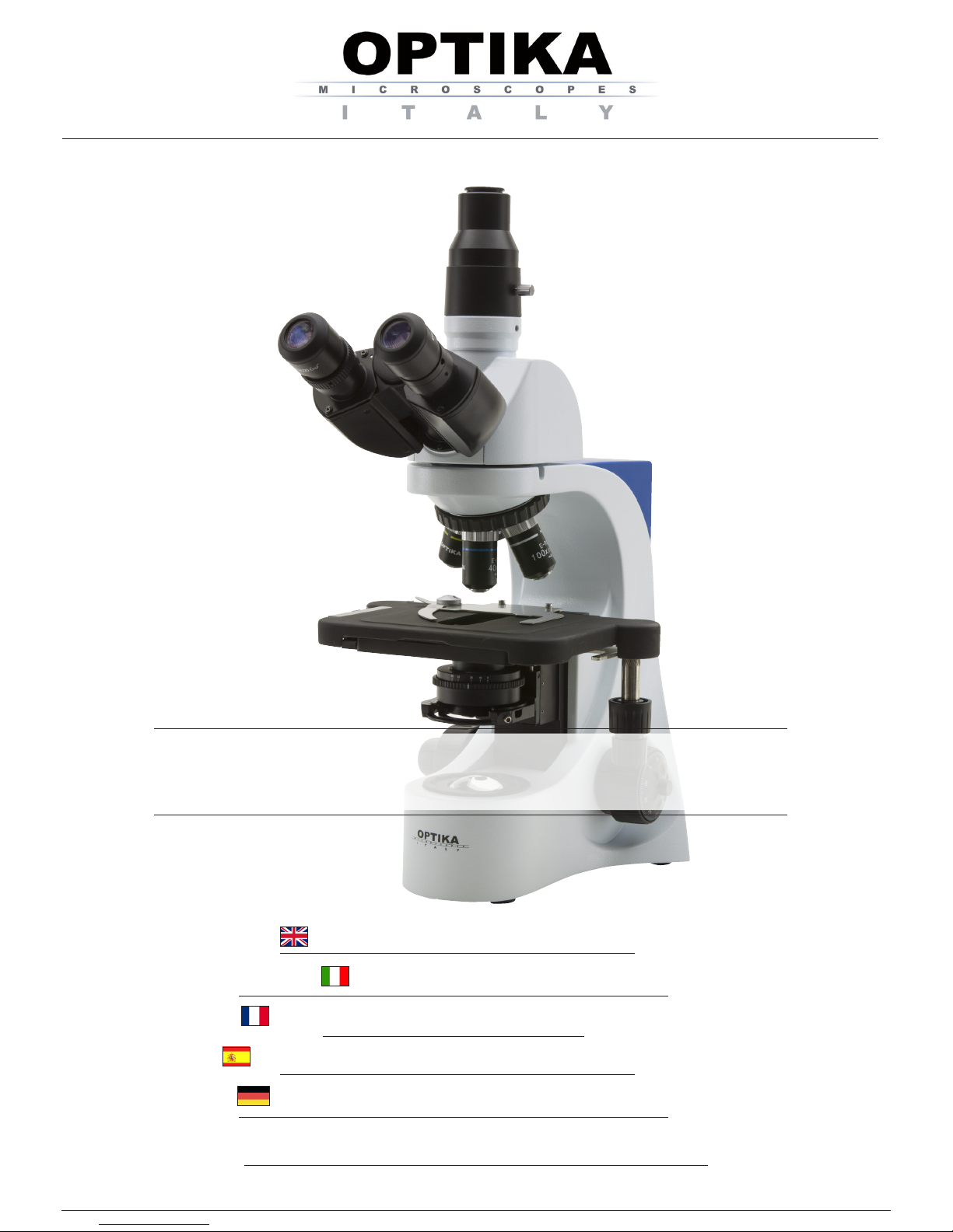
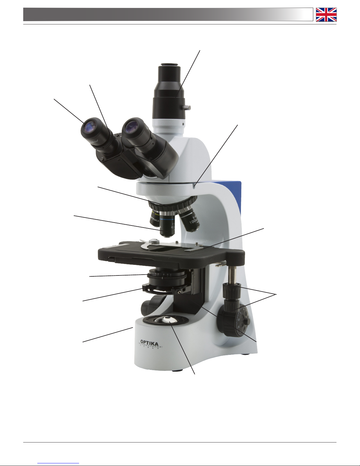
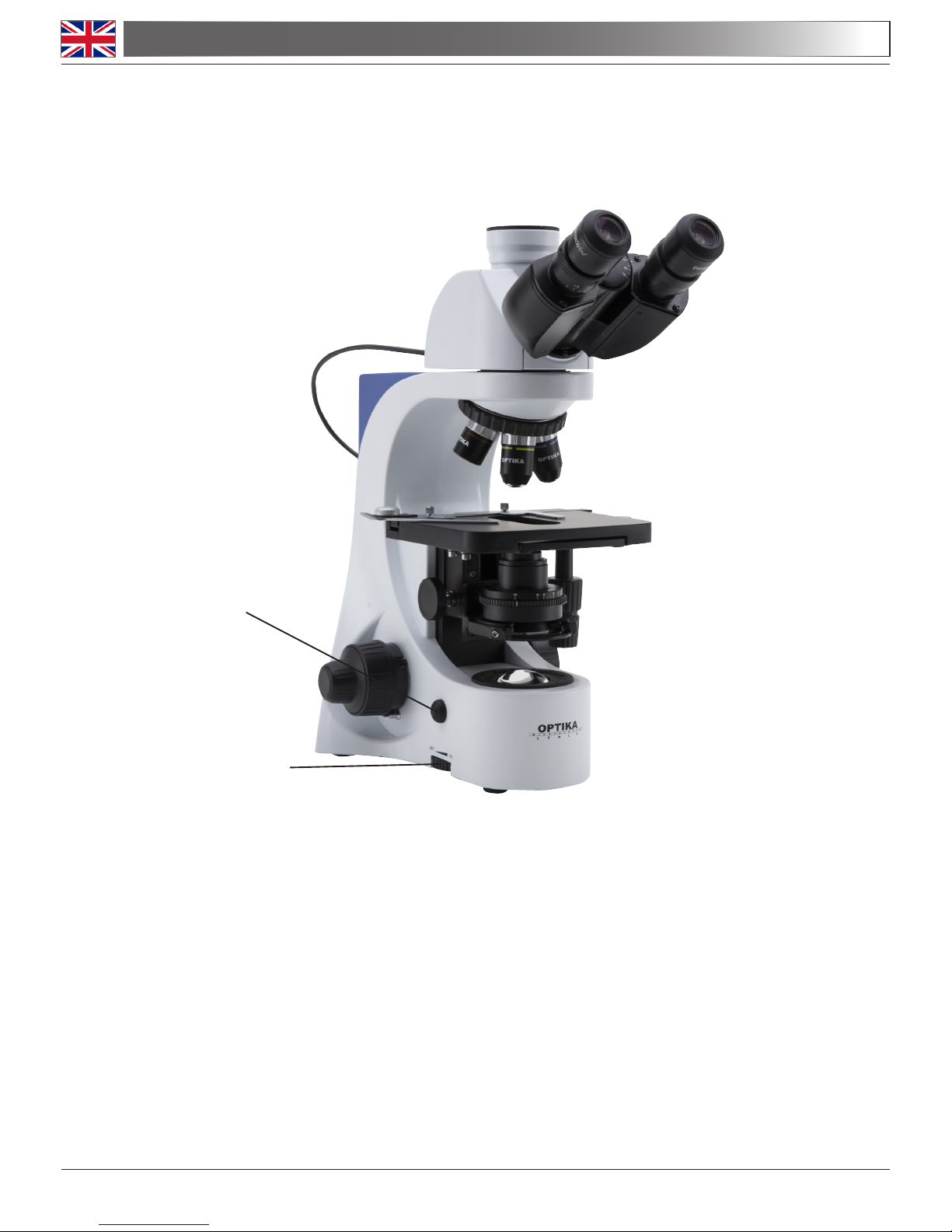
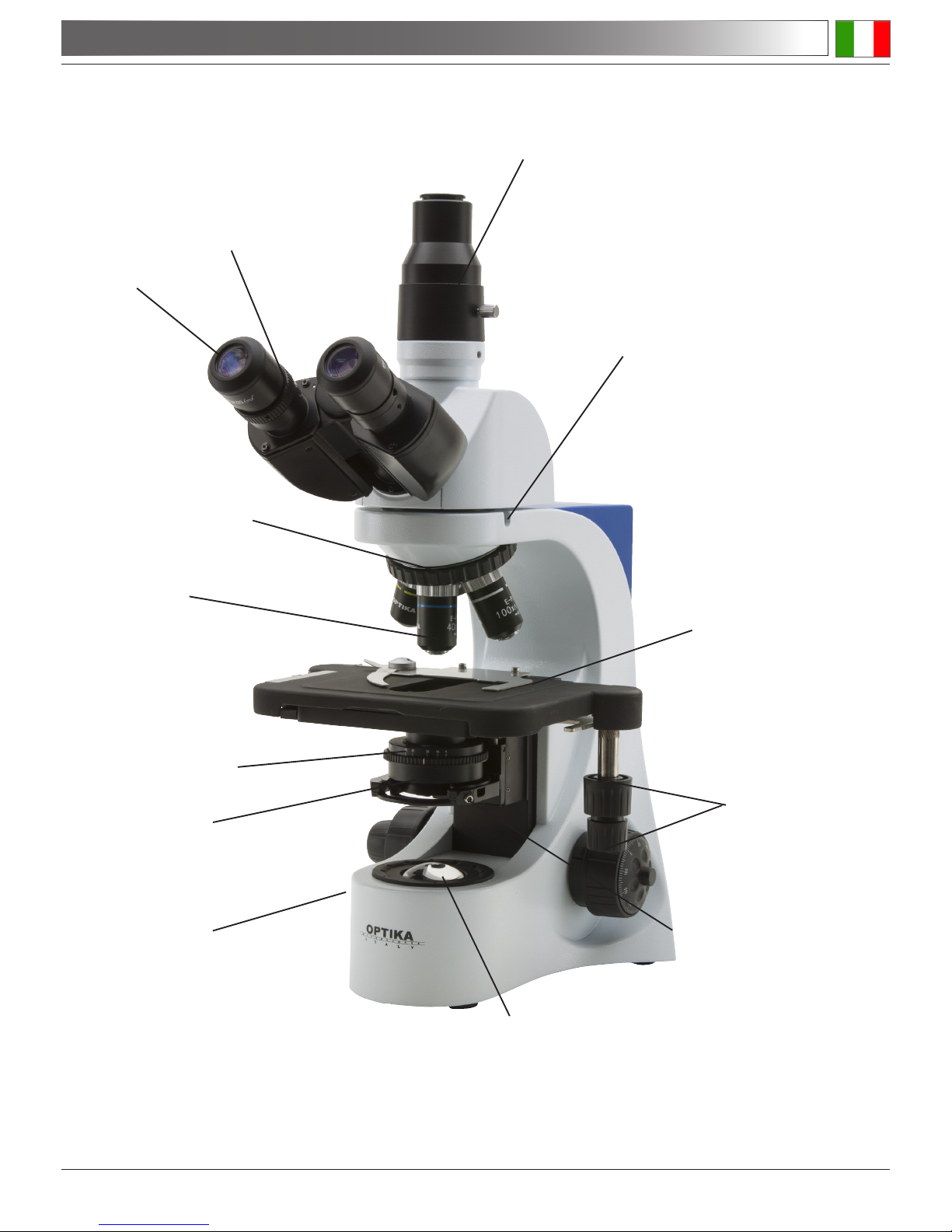
1.0 DESCRIPTION
PHOTO/VIDEO PORT
HEAD LOCKING
SCREW (1)
REVOLVING NOSEPIECE
STAGE
TRANSLATION KNOBS
BRIGHTNESS
ADJUSTMENT
(LEFT SIDE)
CONDENSER CENTERING
SCREWS (2)
IRIS DIAPHRAGM (3)
EYEPIECE
CONDENSER
LED ILLUMINATOR
OBJECTIVE
DIOPTRIC
ADJUSTMENT RING
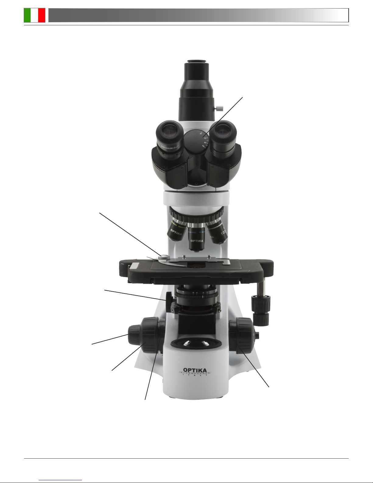
Page 4
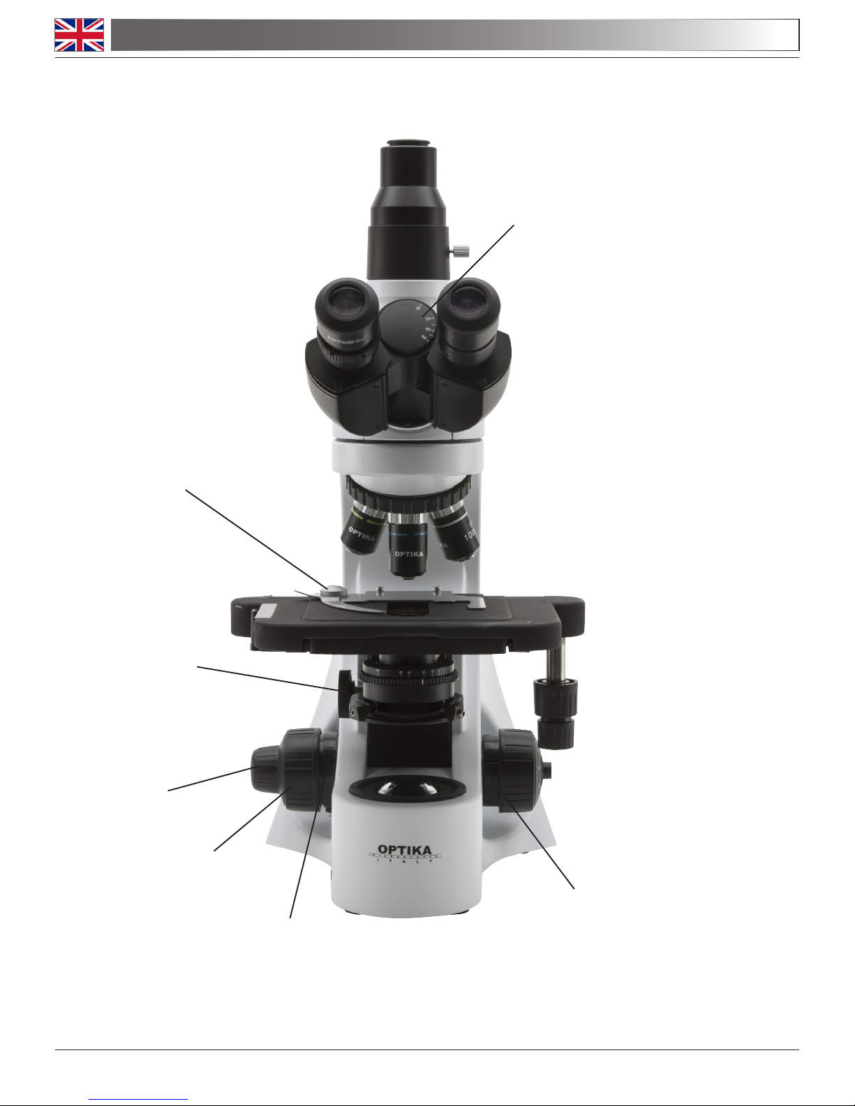
SLIDE CLAMP
FINE FOCUSING KNOB
CONDENSER HEIGHT
ADJUSTMENT (4)
TENSION
ADJUSTMENT KNOB (5)
COARSE FOCUSING KNOB
1.0 DESCRIPTION
FOCUS STOP KNOB
INTERPUPILLARY DISTANCE

Page 5
This microscope is a scientic precision instrument designed to last for many years with a minimum of maintenance. It is built to high optical and mechanical standards and to withstand daily use.
Optika reminds you that this manual contains important information on safety and maintenance, and that it
must therefore be made accessible to the instrument users.
Optika declines any responsibility deriving from instrument uses that do not comply with this ma-nual.
2.1 Safety guidelines
This manual contains important information and warnings regarding safety about installation, use and
maintenance of the microscope B-380. Please read this manual carefully before using the equipment.
To ensure safe use, the user must read and follow all instructions in this manual. OPTIKA products
are designed for safe use in normal operating conditions. The equipment and accessories described
in the manual are manufactured and tested according to industry standards for safety instrumentation
laboratory. Misuse can cause personal injury or damage to the instrument. Keep this manual at hand
close to the instrument, for an easy consultation.
2.2 Electrical safety
Before connecting the power cord to wall outlet, ensure that your mains voltage for your region corresponds to the voltage supply of the instrument, and that the illuminator’s switch is in position OFF. The
user must observe the safety regulations in force in his region. The instrument is equipped with CE
safety marking, in any case the user has full responsibility concerning the safe use of that instrument.
2.3 Warning/Caution symbols used in this manual
The user should be aware of safety aspects when using the instrument. Warning or hazard symbols
are shown below. These symbols are used in this manual.
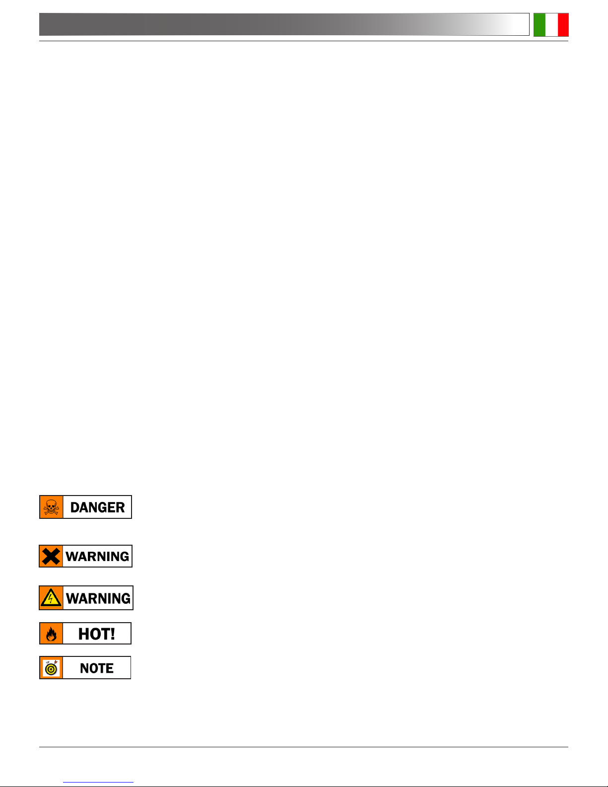
The instructions on this symbol to avoid possible severe personal injuries.
Warning of use; the incorrect operation on the instrument can cause damages
to the person or instrument.
Possibility of electric shock.
Attention: high temperature surfaces. Avoid direct contact.
Technical notes or usage tips.
2.0 INTRODUCTION
Page 6
3.0 UNPACKING AND ASSEMBLY
The microscope is located in a styrofoam moulded packaging. After removing the adhesive tape from
all packaging, lift the top half of the packaging. Pay attention not to drop or damage the optical com-
ponents (objectives and eyepieces). Extract the microscope from its packaging with both hands (one
around the top arm and one around the base) and place it on a stable surface. Keep it away from
solvents, chemical vapors and excessive moisture. Avoid high temperature environments, the direct
sunshine and excessive vibrations, which could affect the performance of the instrument.
3.1 Operating environment
Temperature: : 10 - 36°C (50 – 96.8°F)
Relative humidity: 0 – 85% up to 30°C (86°F)
3.2 Unpacking microscope
Control the packaging to ensure that all material is present. We recommend that you take note of all
the accessories to facilitate any future orders of spare parts and technical support calls. Make sure
that in the packaging no small accessories or small parts remain. Please keep the original packaging
in a safe place for future transport needs of microscope or accessories.
Never touch the glass surfaces such as lenses or lters. Traces of grease or other residues can re-
duce the vision quality of the nal image and corrode the surface of lenses in a short time.
3.3 Installing the microscope
Set the optical head on the top arm through the locking screw. Insert the eyepieces into the tubes and
lock them with the small screws which are located to the side of the tubes. Remove the protective lm
from the stage of the microscope.
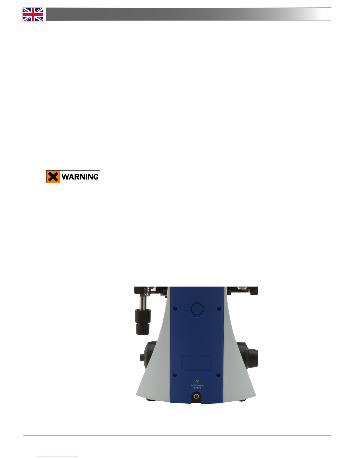
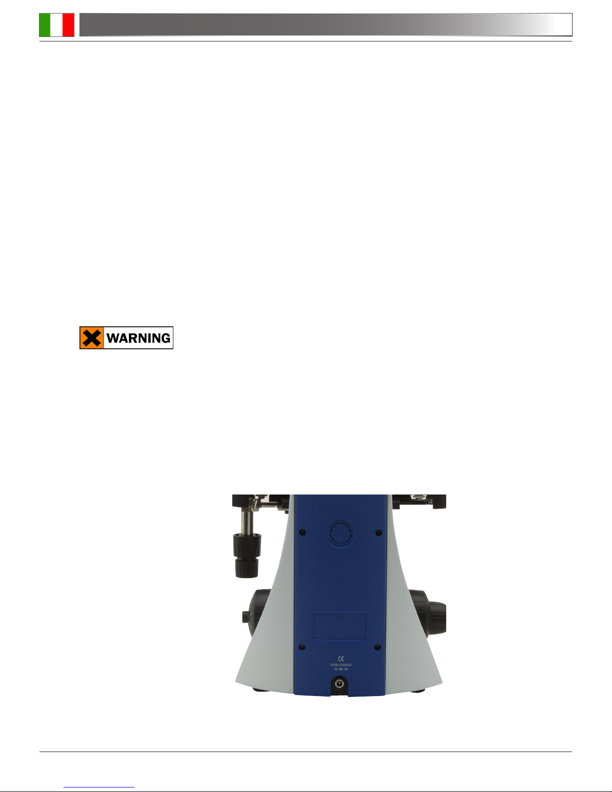
3.4 Connect the external power supply into the socket at the base

Page 7
Once positioned and installed with the necessary components, the microscope is ready to be used.
Your microscope is a laboratory instrument designed to last. Handle it always carefully and avoid
abrupt vibrations or shocks.
Always disconnect the power cable from the microscope when not in use for long time, while you
clean it or when you perform any maintenance.
AVOID DISASSEMBLING THE INSTRUMENT
Do not disassemble the instrument. This entails the cancellation of the warranty and may cause malfunction.
4.1 Observation head
Loosen the lock-screw (1), turn the observation head to a comfortable position for observation, and
then lock the lock-screw.
4.2 Place the specimen on the stage
Lock the specimen slide on the mechanical stage using the slide clamp. Ensure that the specimen is
centred over the stage opening by adjusting the coaxial knobs of the stage.
4.3 Illumination system settings
The microscope is tted with a white LED illuminator. Before turning on the illumination system, read
the section 5.3 about electrical safety precautions. Insert the plug of the cable into the power socket
and turn on the switch on the side of the main body. Turn the brightness adjustment knob to a bright-
ness suitable for observation.
4.4 Adjust interpupillary distance
Hold the right and left parts of the observation head with both hands and adjust the interpupillary dis-
tance by turning the two parts until one circle of light can be seen.
The white dot (°) placed on the left eyepiece shows the set interpupillary distance. Just remember this
value to help on later settings.
4.5 Focus tension adjustment
The tension of the coarse focusing knob is preset by factory. To change the tension according to your
preference, just rotate the knob (5) clockwise in order to increase it.
Excessive tension could damage the mechanism of focus. A too loosed tension causes the descent of
the stage by gravity or a sudden loss of focus. In this case, rotate the knob (5) to increase the tension.
4.0 USING THE MICROSCOPE
Page 8
4.6 Diopter adjustment
Turn the dioptric adjustment ring on the left eyepiece to the zero position. Turn the coarse focus knob
in order to focus the slide with an objective with low magnication. Adjust the ne focus knob until you
obtain a clear and dened picture observing with the right eye, and then act on the left dioptric compensation ring observing with the left eye. When the image appears in focus, choose the necessary
objective with the revolving nosepiece.
4.7 Condenser
Raise or lower the condenser through the knob (4) to obtain a clear and uniform illumination of the
sample.
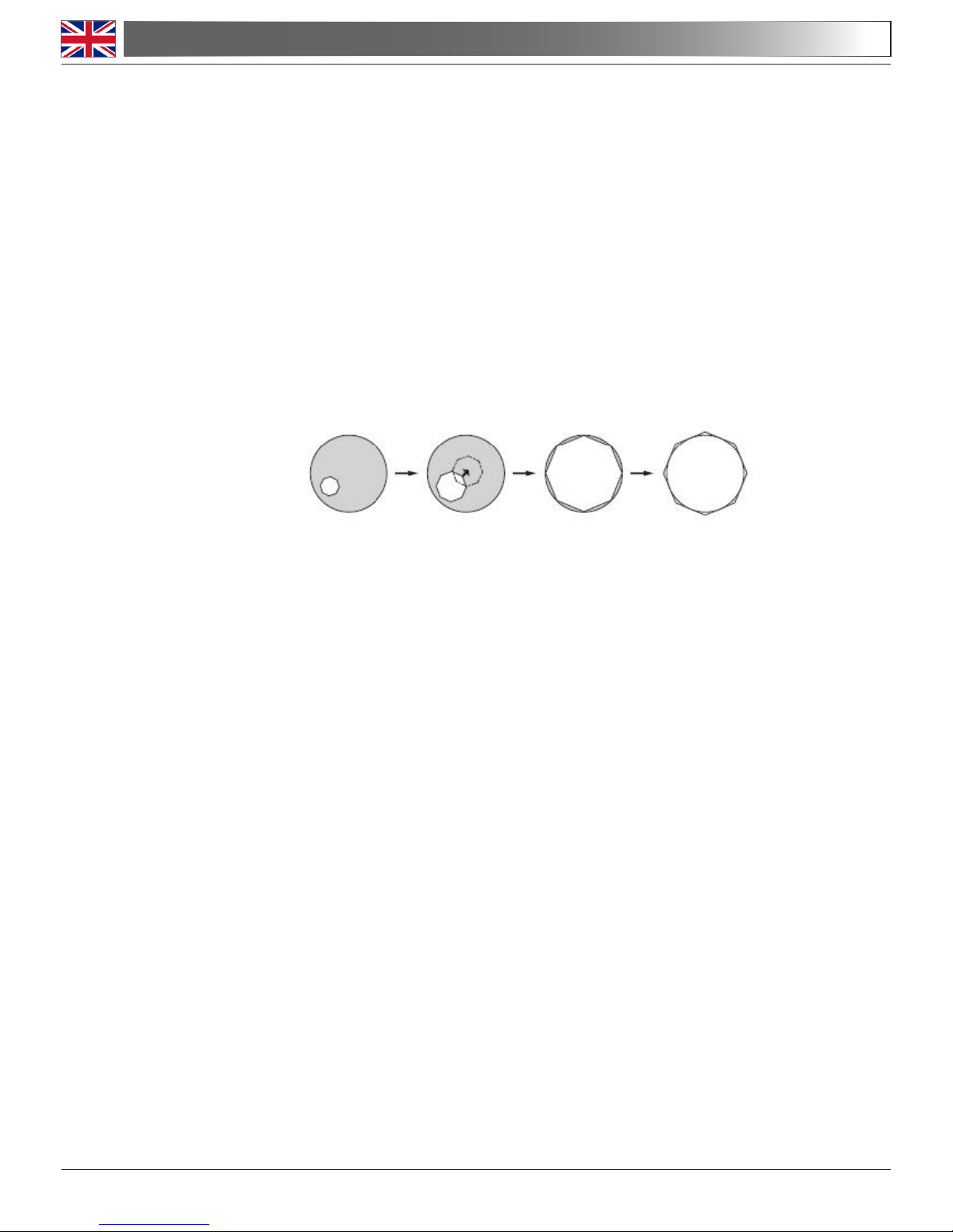
To center the condenser: completely close the iris diaphragm (3). Using the condenser centering
screws (2), move the diaphragm in the center of the eld of view. Then gradually expand the diaphragm until it is tangent to the edges of the eld of view. If necessary, you can perform an additional
adjustment.
The condenser is centered when the edges of iris diaphragm are tangent to the eld of view.
4.8 Numerical aperture setting
The value of the numerical aperture (N.A.) of the diaphragm is an indication of the contrast of the il-
lumination system. Matching the value of illumination system’s N.A. with that of the objective ensures
the best results in terms of contrast and image quality. To set the numerical aperture of the Illuminator,
adjust the opening of the iris diaphragm (3). In this way you control contrast and image resolution. For
samples with low contrast set the iris to about 75% of the value of the objective’s numerical aperture.
4.9 Phase rings centering (models B-380PH)
For models equipped with phase contrast set, you have to perform the centering of the phase rings.
Remove an eyepiece from the head and insert the centering telescope in the empty tube.
4.0 USING THE MICROSCOPE
Page 9
Insert the 10x objective rotating the nosepiece.
Rotate the turret of the condenser until you reach the inscription “10”.
Loosening the lock screw of the centering telescope, focus on the light ring that you observe.
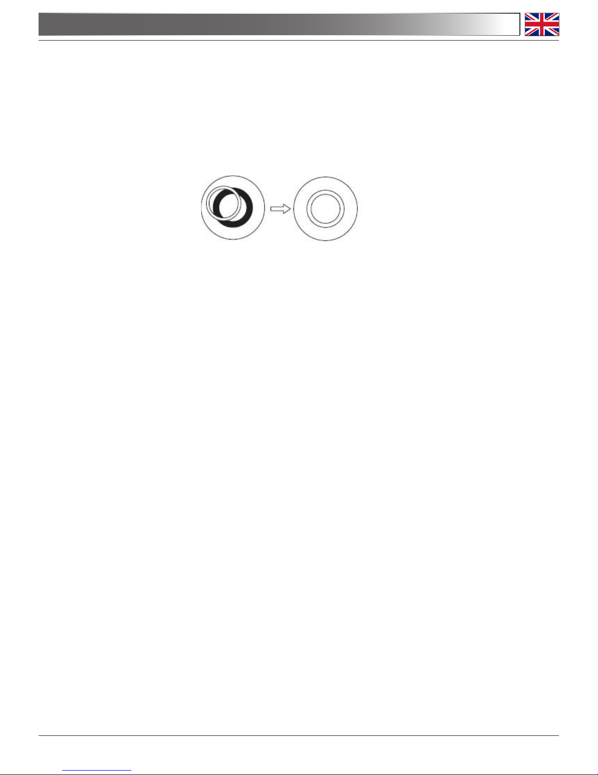
Rotate the two centering screws in order to move the bright ring until it is perfectly aligned with the
dark ring.
Repeat for the other objectives (only as a verication of the correct centering).
Phase rings will be centered when you see an image like this:
4.0 USING THE MICROSCOPE
Page 10
B-382-ALC models have a special function called “Automatic Light Control”.
The level of light is adjusted by the microscope in order to maintain the same level as the one the user
has chosen, no matter if the aperture of the diaphragm changes, another objective is inserted, opacity
of the sample changes, etc.
1) Set the focus on the sample as described in the previous chapters, using the objective of your
choice.
2) Rotate the brightness adjustment knob in order to get a comfortable level of illumination. NOTE:
ALC system works properly with medium-to-high light intensity, do not set the brightness to a minimum
level.
3) Press the ALC button on the side of the microscope.
Now the ALC system is working: if you open or close the aperture diaphragm or change objective, the
system will try to maintain the same level of illumination as the one you stored when you pressed the
button.
4) Press the ALC button again to return to a manual control of illumination.
5.0 AUTOMATIC LIGHT CONTROL (B-382-ALC MODELS)
BRIGHTNESS
ADJUSTMENT KNOB
ALC BUTTON

Page 11
6.1 Microscopy environment
This microscope is recommended to be used in a clean, dry and shock free environment with a tem-
perature of 0-40°C and a maximum relative humidity of 85 % (non condensing). Use a dehumidier if
needed.
6.2 Before and after using the microscope
- The microscope should always be kept vertically when moving it and be careful so that no moving
parts, such as the eyepieces, fall out.
- Never mishandle or impose unnecessary force on the microscope.
- Never attempt to service the microscope yourself.
- After use, turn off the light immediately, cover the microscope with the included dust-cover, and keep
it in a dry and clean place.
6.3 Precautions for a safe use
- Before plugging in the power cord with the supply, make sure that the supplying voltage of your region
matches with the operation voltage of the equipment and that the lamp switch is in off-position.
- Users should observe all safety regulations of the region. The equipment has acquired the CE safety
label. However, users do have full responsibility to use this equipment safely.
6.4 Cleaning the optics
- If the optical parts need to be cleaned try rst to: use compressed air.
- If that is not sufcient: use a soft lint-free piece of cloth with water and a mild detergent.
- And as a nal option: use the piece of cloth moistened with a 3:7 mixture of ethanol and ether.
Note: ethanol and ether are highly ammable liquids. Do not use them near a heat source, near
sparks or near electric equipment. Use these chemicals in a well ventilated room.
- Remember to never wipe the surface of any optical items with your hands. Fingerprints can damage
the optics.
- Do not disassemble objectives or eyepieces in attempt to clean them.
If you need to send the microscope to Optika for maintenance, please use the original packaging.
6.0 MAINTENANCE
Page 12
7.0 RECOVERY AND RECYCLING
Art.13 Dlsg 25 july 2005 N°151. “According to directives 2002/95/EC, 2002/96/EC and 2003/108/EC
relating to the reduction in the use of hazardous substances in electrical and electronic equipment
and waste disposal.”
The basket symbol on equipment or on its box indicates that the product at the end of its useful life
should be collected separately from other waste.
The separate collection of this equipment at the end of its lifetime is organized and managed by
the producer. The user will have to contact the manufacturer and follow the rules that he adopted
for end-of-life equipment collection. The collection of the equipment for recycling, treatment and en-
vironmentally compatible disposal, helps to prevent possible adverse effects on the environment
and health and promotes reuse and/or recycling of materials of the equipment. Improper dispos-
al of the product involves the application of administrative penalties as provided by the laws in force.


Pagina 14
INDICE
1.0 DESCRIZIONE pag. 15
2.0 INTRODUZIONE pag. 17
3.0 RIMOZIONE DELL’IMBALLAGGIO E MONTAGGIO pag. 18
4.0 USO DEL MICROSCOPIO pag. 19
4.1 Regolazione della testata di osservazione
4.2 Posizionamento del campione sul tavolino portapreparati
4.3 Regolazione del sistema di illuminazione
4.4 Regolazione della distanza interpupillare
4.5 Regolazione della tensione di messa a fuoco
4.6 Regolazione della compensazione diottrica
4.7 Regolazione del condensatore
4.8 Regolazione dell’apertura numerica
4.9 Centraggio degli anelli di fase (B-380PH)
5.0 AUTOMATIC LIGHT CONTROL (MODELLO B-382-ALC) pag. 22
6.0 MANUTENZIONE pag. 23
6.1 Ambiente di lavoro
6.2 Prima e dopo l’uso del microscopio
6.3 Precauzioni per un utilizzo sicuro
6.4 Pulizia delle ottiche
7.0 MISURE ECOLOGICHE pag. 24
Pagina 15
1.0 DESCRIZIONE
USCITA FOTO/VIDEO
VITE SERRAGGIO
TESTA (1)
REVOLVER PORTAOBIETTIVI
TAVOLINO
TRASLATORE
MANOPOLE REGOLAZIONE
SPOSTAMENTO TAVOLO
REGOLAZIONE
LUMINOSITÀ
(LATO SINISTRO)
VITI DI CENTRAGGIO
CONDENSATORE (2)
DIAFRAMMA A IRIDE (3)
OCULARI
CONDENSATORE
ILLUMINATORE A LED
OBIETTIVI
ANELLO DI REGOLAZIONE
DIOTTRICA
Pagina 16
1.0 DESCRIZIONE
PINZA PORTAPREPARATI
COMANDO FUOCO
MICROMETRICO
REGOLAZIONE ALTEZZA
DEL CONDENSATORE (4)
REGOLAZIONE DELLA
TENSIONE (5)
COMANDO FUOCO
MACROMETRICO
LEVA DI BLOCCO
FOCUS
DISTANZA INTERPUPILLARE
Pagina 17
Il presente microscopio è uno strumento scientico di precisione studiato per durare molti anni con una manutenzione minima, essendo costruito secondo i migliori standard ottici e meccanici e progettato per un utilizzo
quotidiano.
Optika ricorda che il presente manuale contiene informazioni importanti per un uso sicuro e una corretta manutenzione dello strumento. Esso deve quindi essere accessibile a chiunque lo utilizzi.
Optika declina ogni responsabilità derivante da un uso improprio dei suoi strumenti non indicato dalla presente guida.
2.1 Avvertenze di sicurezza
Questo manuale contiene importanti informazioni e avvertenze riguardanti la sicurezza riguardo l’installazione, l’utilizzo e la manutenzione del microscopio B-380. Si raccomanda di leggere attentamente il manuale prima di qualsiasi utilizzo dello strumento. Per assicurare un utilizzo sicuro l’utente deve
leggere e seguire tutte le istruzioni poste nel presente manuale.
I prodotti OPTIKA sono studiati per un utilizzo sicuro in condizioni operative normali. Lo strumento e
gli accessori descritti nel manuale sono realizzati e testati secondo standard industriali di sicurezza
per strumentazione da laboratorio.
L’utilizzo non corretto può causare lesioni alla persona o danni allo strumento.
Mantenere questo manuale a portata di mano vicino allo strumento, per una facile consultazione.
2.2 Precauzioni di sicurezza elettrica
Prima di collegare il cavo di alimentazione alla presa di rete, assicurarsi che la tensione di rete della
vostra regione corrisponda alla tensione di alimentazione dello strumento, e che l’interruttore dell’illuminatore sia in posizione spenta.
L’utente deve osservare la regolamentazione riguardante la sicurezza in vigore nel proprio Stato. Lo
strumento è dotato di marcatura di sicurezza CE, in ogni caso l’utente ha piena responsabilità riguardo all’utilizzo sicuro dello strumento stesso.
2.3 Simboli di avvertenza/pericolo usati nel manuale
L’utente deve essere a conoscenza degli aspetti legati alla sicurezza nel momento in cui utilizza lo
strumento. I simboli di avvertenza o pericolo sono indicati sotto. Tali simboli sono utilizzati in questo
manuale di istruzioni.
Seguire le istruzioni contrassegnate da questo simbolo per evitare possibili gra-
vi danni alle persone.
Avvertimento di utilizzo; la non corretta operazione sullo strumento può causare
danni alla persona o allo strumento.
Possibilità di shock elettrico.
Attenzione: superci ad elevata temperatura. Evitare il contatto diretto.
Note tecniche o consigli di utilizzo.
2.0 INTRODUZIONE
Pagina 18
3.0 RIMOZIONE DELL’IMBALLAGGIO E MONTAGGIO
Il microscopio si trova in un imballaggio di polistirolo espanso stampato. Dopo aver tolto il nastro ade-
sivo da tutti gli imballi, sollevare la metà superiore dell’imballaggio. Fare attenzione a non far cadere o
danneggiare le componenti ottiche (obiettivi e oculari). Estrarre il microscopio dal suo imballaggio con
entrambe le mani (una intorno al braccio e una intorno alla base) e appoggiarlo su di un piano stabile.
Mantenere lo strumento lontano da solventi, vapori chimici ed eccessiva umidità. Evitare anche ele-
vate escursioni termiche dell’ambiente di utilizzo, l’esposizione diretta ai raggi solari ed eccessive
vibrazioni, che potrebbero compromettere le performance dello strumento.
3.1 Condizioni operative ambientali
Temperatura: 10 - 36°C (50 – 96.8°F)
Umidità relativa: 0 – 85% no a 30°C (86°F)
3.2 Rimozione dell’imballaggio
Controllate l’imballo del microscopio per assicurarvi che tutto il materiale sia presente. Si consiglia
di prendere nota di tutti gli accessori in modo da facilitare eventuali ordini futuri di pezzi di ricambio
e chiamate all’assistenza tecnica. Assicuratevi che nell’imballo non rimangano piccoli accessori o
piccole parti. Conservate l’imballo originale in un posto sicuro per future necessità di trasporto del
microscopio o dei suoi accessori.
Evitare di toccare le superci ottiche come lenti, ltri o vetri. Tracce di grasso o altri residui possono
ridurre la qualità visiva dell’immagine nale e corrodere la supercie delle ottiche in breve tempo.
3.3 Installazione del microscopio
Fissare la testata di osservazione sulla parte superiore del braccio mediante l’apposita vite di serrag-
gio. Inserire gli oculari nei tubi porta-oculari e ssarli con le piccole viti che si trovano al lato dei tubi.
Togliere la pellicola di protezione dal piano del microscopio.
3.4 Connettere l’alimentazione esterna nella presa posta nella base dello stativo.

Pagina 19
Una volta posizionato e installato con i necessari componenti, il microscopio è pronto per l’utilizzo.
Il vostro microscopio è uno strumento da laboratorio progettato per durare a lungo. Maneggiatelo
sempre con cura ed abitate brusche vibrazioni o colpi.
Scollegare sempre il cavo di alimentazione dal microscopio quando non viene utilizzato per lunghi
tempi, mentre lo si pulisce o quando si esegue una qualsiasi manutenzione.
EVITARE DI SMONTARE LO STRUMENTO
Non disassemblare lo strumento. Questo comporta l’annullamento della garanzia e potrebbe causare
malfunzionamenti.
4.1 Regolazione della testata di osservazione
Allentare la vite di serraggio (1), ruotare la testata no a trovare una posizione comoda per l’osserva-
zione e quindi avvitarla nuovamente.
4.2 Posizionamento del campione sul tavolino portapreparati
Fissare il vetrino con preparato al piano meccanico mediante l’apposita pinzetta per il sostegno dei
campioni. Regolando le manopole coassiali del piano portaoggetti, assicurarsi che il vetrino si trovi al
centro del campo di osservazione.
4.3 Regolazione del sistema di illuminazione
Il microscopio è dotato di un illuminatore a LED bianco. Prima di accedere il sistema di illuminazione,
leggere attentamente la sezione 5.3 sulle precauzioni per un utilizzo sicuro. Inserire lo spinotto del
cavo nella presa di alimentazione e premere il pulsante di accensione posto sul lato dello stativo.
Ruotando la manopola di regolazione della luminosità, cercare la luce ideale per l’osservazione.
4.4 Regolazione della distanza interpupillare
Regolare la distanza interpupillare dei portaoculari sulla testata no ad ottenere la visione di un unico
campo luminoso circolare allargando o stringendo le parti destra e sinistra della testata di osservazio-
ne con entrambe le mani.
Il puntino (°) posto sul portaoculare sinistro indica la propria distanza interpupillare. Memorizzare que-
sto valore per facilitare regolazioni successive.
4.5 Regolazione della tensione di messa a fuoco
La tensione della messa a fuoco macrometrica è preimpostata dalla fabbrica. Per modicare la ten-
sione in base alle proprie preferenza ruotare la ghiera (5) in senso orario per aumentare la tensione.
Una tensione eccessiva potrebbe danneggiare il meccanismo di messa fuoco. Una tensione troppo
ridotta provoca la discesa del tavolino per gravità o una perdita di fuoco repentina. In questo caso
ruotare la ghiera per aumentare la tensione.
4.0 USO DEL MICROSCOPIO

Pagina 20
4.6 Regolazione della compensazione diottrica
Ruotare l’anello di compensazione diottrica sull’oculare sinistro no alla posizione di zero. Ruotare la
manopola di messa a fuoco macrometrica per focalizzare il vetrino con un obiettivo con basso potere
di ingrandimento. Regolare la manopola di messa a fuoco micrometrica no ad ottenere un’immagine
chiara e denita osservando con l’occhio destro, quindi ripetere l’operazione con l’anello di compensazione diottrica sinistro e l’occhio sinistro. Quando l’immagine appare a fuoco, scegliere l’obiettivo
necessario con l’apposito revolver.
4.7 Regolazione del condensatore
Alzare o abbassare il condensatore mediante l’apposita manopola (4) per ottenere un’illuminazione
chiara ed uniforme dell’oggetto.
Per centrare il condensatore: utilizzando la ghiera del diaframma di apertura ad iride (3) chiudere
completamente il diaframma. Utilizzando le viti di centraggio del condensatore (2), spostare il diaframma al centro del campo visivo. Poi allargare gradualmente il diaframma no a che sia tangente ai
bordi del campo visivo. Se necessario eseguire una ulteriore regolazione.
Il condensatore è centrato quando i bordi del diaframma sono tutti tangenti al campo visivo.
4.8 Regolazione dell’apertura numerica (A.N.)
Il valore dell’apertura numerina (A.N.) del diaframma è l’indicazione del contrasto del sistema di illuminazione.
Facendo coincidere il valore di A.N. del sistema di illuminazione con quello dell’obiettivo si ottengono
i migliori risultati in termini di contrasto e di qualità dell’immagine.
Per impostare l’apertura numerica dell’illuminatore, regolare l’apertura del diaframma a iride (3). In
questo modo si controllano contrasto e risoluzione dell’immagine.
Per campioni a basso contrasto impostare il diaframma a circa il 75% del valore dell’apertura numerica dell’obiettivo.
4.9 Centraggio degli anelli di fase (B-380PH)
Per i modelli dotati di osservazione in contrasto di fase è necessario eseguire il centraggio degli anelli
di fase.
Rimuovere un oculare dalla testata ed inserire il telescopio di centramento (CT) nel portaoculare
vuoto.
4.0 USO DEL MICROSCOPIO

Pagina 21
Inserire l’obiettivo 10x ruotando il revolver portaobiettivi.
Ruotare la torretta del condensatore no a visualizzare la scritta “10”.
Ruotare le due viti di centraggio in modo tale che l’anello luminoso sia perfettamente allineato con
l’anello scuro.
Ripetere l’operazione per gli altri obiettivi (solo come verica di un corretto centraggio).
Gli anelli di fase saranno centrati quando si osserva un’immagine di questo tipo:
4.0 USO DEL MICROSCOPIO

Pagina 22
Il modello B-382-ALC ha una speciale funzione denominata “Automatic Light Control”.
Il livello di luminosità impostato sul microscopio viene mantenuta sempre costante così come ssata
dall’operatore, indipendentemente dal fatto che cambi l’apertura del diaframma, venga inserito un
diverso obiettivo, o cambi il grado di opacità del campione osservato, ecc.
1) 1) Mettere a fuoco il campione come indicato nel capitolo precedente, utilizzando l’obiettivo da voi
prescelto.
2) Ruotate la manopola di regolazione della luminosità no ad ottenere il grado di illuminazione per voi
ottimale. NOTE: il sistema ALC funziona al meglio ad una intensità luminosa medio-alta, non ssate
la luminosità al minimo.
3) Premete il pulsante ALC sul lato sinistro del microscopio.
Ora il sistema ALC è funzionante: se aprirete o chiuderete il diaframma di apertura o cambierete
obiettivo, il sistema lavorerà per mantenere inalterato il livello di luce da voi ssato al momento in cui
avere premuto il pulsante ALC.
4) Premere nuovamente il pulsante ALC per tornare al controllo manuale della luminosità.
5.0 AUTOMATIC LIGHT CONTROL (MODELLO B-382-ALC)
MANOPOLA
REGOLAZIONE
LUMINOSITÀ
PULSANTE ALC

Pagina 23
6.1 Ambiente di lavoro
Si consiglia di utilizzare il microscopio in un ambiente pulito e secco, privo di urti, ad una temperatura
fra 0°C e 40°C e con una umidità relativa massima dell’85% (in assenza di condensazione). Si consiglia l’uso di un deumidicatore se necessario.
6.2 Prima e dopo l’uso del microscopio
- Tenere il microscopio sempre in posizione verticale quando lo si sposta. Assicurarsi inoltre che le parti
mobili, ad esempio gli oculari, non cadano.
- Non maneggiare senza precauzioni e non adoperare inutile forza sul microscopio.
- Non cercare di provvedere da soli alla riparazione.
- Dopo l’uso spegnere immediatamente la lampada, coprire il microscopio con l’apposita custodia anti-
polvere in dotazione e tenerlo in un luogo asciutto e pulito.
6.3 Precauzioni per un utilizzo sicuro
- Prima di collegare il cavo di alimentazione alla rete elettrica assicurarsi che il voltaggio locale sia idoneo a quello dell’apparecchio e che l’interruttore della lampada sia posizionato su off.
- Attenersi a tutte le precauzioni di sicurezza della zona in cui ci si trova ad operare. L’apparecchio è
omologato secondo le norme di sicurezza CE. Gli utenti hanno comunque piena responsabilità nell’utilizzo sicuro del microscopio.
6.4 Pulizia delle ottiche
- Qualora le ottiche necessitino di essere pulite, utilizzare prima di tutto aria compressa.
- Se questo non fosse sufciente usare un panno non slacciato, inumidito con acqua e un detergente
delicato.
- Come ultima opzione è possibile usare un panno inumidito con una soluzione 3:7 di alcol etilico ed
etere.
Attenzione: l’alcol etilico e l’etanolo sono sostanze altamente inammabili. Non usarle vicino ad una
fonte di calore, a scintille o presso apparecchiature elettriche. Le sostanze devono essere adoperate
in un luogo ben ventilato.
- Non stronare la supercie di nessun componente ottico con le mani. Le impronte digitali possono
danneggiare le ottiche.
- Non smontare gli obiettivi o gli oculari per cercare di pulirli.
Si prega di utilizzare l’imballaggio originale nel caso in cui fosse necessario rispedire il microscopio ad
Optika per la manutenzione.
6.0 MANUTENZIONE

Pagina 24
7.0 MISURE ECOLOGICHE
Ai sensi dell’articolo 13 del decreto legislativo 25 luglio 2005 n°151. “Attuazione delle direttive
2002/95/CE, 2002/96/CE e 2003/108/CE, relative alla riduzione dell’uso di sostanze pericolose nelle
apparecchiature elettriche ed elettroniche, nonché allo smaltimento dei riuti”.
Il simbolo del cassonetto riportato sulla apparecchiatura o sulla sua confezione indica che il prodotto alla
ne della propria vita utile deve essere raccolto separatamente degli altri riuti. La raccolta differenziata
della presente apparecchiatura giunta a ne vita è organizzata e gestita dal produttore.
L’utente che vorrà disfarsi della presente apparecchiatura dovrà quindi contattare il produttore e seguire
il sistema che questo ha adottato per consentire la raccolta separata dell’apparecchiatura giunta a ne
vita.
L’adeguata raccolta differenziata per l’avvio successivo della apparecchiatura dismessa al riciclaggio,
al trattamento e allo smaltimento ambientalmente compatibile contribuisce ad evitare possibili effetti
negativi sull’ambiente e sulla salute e favorisce il reimpiego e/o riciclo dei materiali di cui è composta
l’apparecchiatura.
Lo smaltimento abusivo del prodotto da parte del detentore comporta l’applicazione delle sanzioni am-
ministrative previste dalla normativa vigente.


Page 26
SOMMAIRE
1.0 DESCRIPTION pag. 27
2.0 INTRODUCTION pag. 29
3.0 DÉBALLAGE ET MONTAGE DU MICROSCOPE pag. 30
4.0 UTILISATION DU MICROSCOPE pag. 31
4.1 Réglage de la tête d’observation
4.2 Positionnement de la préparation sur la platine
4.3 Réglage du système d’éclairage
4.4 Réglage de la distance inter pupillaire
4.5 Réglage de la mise au point
4.6 Réglage de la compensation dioptrique
4.7 Réglage du condenseur
4.8 Réglage de l’ouverture numérique
4.9 Centrage des anneaux de phase (B-380PH)
5.0 CONTRÔLE AUTOMATIQUE DE LA LUMIÈRE (MODÈLES B-382ALC) pag. 34
6.0 ENTRETIENT DU MICROSCOPE pag. 35
5.1 Environnement pour l’utilisation
5.2 Conseils avant et après l’utilisation du microscope
5.3 Précautions de sécurité pour l’utilisation
5.4 Nettoyage des optiques
7.0 RECYCLAGE ET RÉCUPÉRATION pag. 36

Page 27
1.0 DESCRIPTION
SORTIE PHOTO VIDÉO
VIS DE FIXATION DE
LA TÊTE (1)
RÉVOLVER
SURPLATINE
MÉCANIQUE
COMMANDES COAXIALES
AJUSTEMENT
LUMINOSITE
(CÔTÉ GAUCHE)
VIS DE RÉGLAGE DE
CONDENSEUR (2)
DIAPHRAGME À IRIS (3)
OCULAIRES
CONDENSEUR
ECLAIRAGE LED
OBJECTIFS
RÉGLAGE DE LA DISTANCE
INTER PUPILLAIRE

Page 28
1.0 DESCRIPTION
PINCE POUR MAINTENIR LES
PRÉPARATIONS
COMMANDE DE MISE AU
POINT MICROMÉTRIQUE
RÉGLAGE DE LA
HAUTEUR DU
CONDENSEUR (4)
COMMANDE DE
RÉGLAGE DE TENSION
(5)
COMMANDE DE MISE
AU POINT
MACROMÉTRIQUE
VERROUILLAGE DU
FOYER
RÉGLAGE DE LA DISTANCE
INTER PUPILLAIRE

Page 29
Ce microscope est un appareil scientique de précision pensé pour durer de nombreuses années avec un
entretient minimum. Pour son élaboration il a été utilisé des éléments optiques et mécaniques de grande qui
le convertisse en un appareil idéal pour une utilisation journalière dans les salles de classes et les laboratoires. Optika informe que ce manuel contient d’importantes informations concernant la sécurité et l’entretient
de ce produit et par conséquent il doit être accessible à toutes personnes susceptibles d’utiliser cet appareil.
Optika décline toute responsabilité dérivant d’une utilisation inappropriée de cet appareil non contemplée
dans ce mode d’emploi.
2.1 Sécurité
Ce manuel contient d’importantes infomations concernant les normes de sécurité à suivre durant
l’installaton, ainsi que sur l’utilisation et l’entretien du microscope B-380. Si raccomanda di leggere
attentamente il manuale prima di qualsiasi utilizzo dello strumento. Il est donc important de lire ce
manuel et de suivre les normes de sécurité.
Les produits OPTIKA peuvent être utilisés en toute sécurité dans des conditions de travail normales.
L’instrument et les accéssoires décrits dans ce manuel ont été realisés et testés selon des standard
industriels de sécurité pour l’instrumentation scientique.
Une utilisation inapropriée risquerait de provoquer des blessures à l’utilisateur et au microscope.
Garder ce manuel à portée de main durnat l’utilisation du microscope.
2.2 Précautions de sécurité électrique
Avant de brancher le cable d’alimentation à la prise, s’assurer que la tension dans votre région corresponde à la tension de l’instrument et que l’interrupteur de l’éclairage soit éteint.
L’utilisateur se doit de suivre les normes de sécurité de son propre pays.
L’instrument a un marquage de sécurité CE, l’utilisateur est responsable de l’utilisation appropriée de
l’instrument.
2.3 Symboles d’avertissement / risque utilisés dans le manuel
Avant d’utiliser l’instrument, l’utilisateur doit connaitre toutes les précautions liées à la sécurité. Les
symboles d’avertissement ou de danger sont indiqués ci-dessous.
Suivez les instructions marquées de ce symbole an d’éviter d’éventuelles
blessures.
Avvertissement concernant l’utilisation; l’utilisation inapproprièe du microscope
riquerait de provoquer des blessures à l’utilisateur et d’abimer l’instrument.
Risque de choc életrique.
Attention: surfaces à haute température. Eviter le contact direct.
Notes techniques et conseils pour l’utilisation.
2.0 INTRODUCTION

Page 30
3.0 DÉBALLAGE ET MONTAGE DU MICROSCOPE
Le microscope est livré dans un emballage en polystyrène.
Après avoir sortie l’emballage en polystyrène de son carton, enlevez la partie supérieure en enlevant
de l’emballage en ayant enlevé au préalable la bande adhésive qui se trouve tout au tour. Faites
bien attention de ne pas endommager les composants optiques (objectifs et oculaires) et évitez que
l’appareil ne tombe. Sortir le microscope de son emballage avec les deux mains (avec une main sou-
tenez le bras du microscope et avec l’autre la base) puis appuyez le sur une table stable.
3.1 Conditions de travail
Temperature: 10 - 36°C (50 – 96.8°F)
Umidité relative: 0 – 85% jusqu’à 30°C (86°F)
3.2 Déballage du microscope
Vérier que tos les éléments composant le microscope soit dans le carton. Il est conseiller de prendre
note de tous les accessoires an de faciliter les éventuelles commandes d’ accessoires de rechange
et les appels à l’assistance téchnique. S’assurer qu’il ne manque aucune petite pièce ou accessoire.
Garder l’emballage original, il se peut que vous ayez à transporter le microscope à nouveau.
Eviter de toucher les optiques, les ltres ou les parties en verre. Des traces de gras ou d’autres salis-
sures risquent de réduire la qualité de l’image et d’abimer la surface des optiques
3.3 Installation du microscope
Positionnez la tête d’observation sur l’extrémité supérieure du corps du microscope et viser les vis de
xations. Introduire les oculaires dans les tubes porte oculaires et xez les avec les petits tourne vis
sur partie latérales des tubes portes oculaires. Enlevez le plastique de protection du corps du micros-
cope.
3.4 Connectez l’alimentation externe dans la prise à la base.

Page 31
Votre microscope est un instrument de laboratoire conçu por durer longtemps. Traitez le avec soin
et évitez de le soumettre à chocs et vibrations. Débranchez toujours le câble d’alimentation quand le
microscope n’est pas utiliser pendant longtemps, lors du nettoyage ou lorsque que vous en effectuez
l’entretien.
NE PAS DEMONTER LINSTRUMENT
Non disassemblare lo strumento. Questo comporta l’annullamento della garanzia e potrebbe causare
malfunzionamenti.
4.1 Réglage de la tête d’observation
Dévissez légèrement les vis de xation de façon à faire pivoter la tête jusqu’à obtenir une position
confortable pour l’observation avant de revisser à nouveau
4.2 Positionnement de la préparation sur la platine mécanique
Fixez la platine à la platine mécanique à l’aide de la pince qui tient la préparation. Réglez les com-
mandes coaxiales qui se situent sur le côté de la platine mécanique, en vous assurant que la platine
se situe au centre du champ de vision.
4.3 Réglage de l’éclairage
Le microscope inclut un éclairage LED blanc. Avant de le connecter le microscope à la prise de cou-
rant et d’allumer l’éclairage lire la section 5.3 concernant les précautions de sécurités. Branchez la
prise du microscope sur le secteur puis appuyer le bouton de mise en marche sur le côté du corps
principal. Utilisez le variateur d’intensité lumineuse an d’obtenir l’éclairage correct pour l’observation.
4.4 Réglage de la distance inter pupillaire
Réglez la distance interpupillaire des tubes portes oculaires jusqu’à obtenir la vision d’un unique
champ lumineux circulaire. Une fois le réglage terminé, tournez les deux anneaux de compensation
dioptrique jusqu’à arriver au zéro sur l’échelle graduée des oculaires.
Le point (°) sur le tube porte oculaire gauche indique la distance inter pupillaire de chacun. Memoriser
cette valeur pour faciliter les réglages succéssifs.
4.5 Réglage de la mise au point
La tension de mise aur point macrométrique a déja été preglée. Pour modier la tension tourner la
commande dans le sens des aiguilles d’une montre pour augmenter la tension. Une tension trop forte
pourrait endommager le mécanisme de la mise au point. Une tension trop faible provoque la descente
de la platine par pesanteur ou une perte de mise au poit soudaine. Dans ce cas tourner la commande
pour augmenter la tension
4.0 UTILISATION DU MICROSCOPE

Page 32
4.6 Réglage de la compensation dioptrique
Tourner l’anneau de réglage dioptrique sur l’oculaire gauche jusqu’à atteindre la position zéro. Enle-
vez la vis qui xe le bouton de l’ouverture de mise au point et desserrez le bouton. Faites la mise au
point de la préparation en tournant la commande micrométrique et en utilisant l’objectif le plus faible.
En observant de l’œil gauche, réglez la commande micrométrique an d’obtenir une image nette.
Répétez l’opération avec l’oeil droit et la commande de droite. En tournant le bouton de réglage de
tension, réglez la tension adaptée à la mise au point. Lorsque l’image est nette, sélectionnez l’objectif
souhaité.
4.7 Réglage du condenseur
Montez ou descendez le condenseur en utilisant la commande correspondante an d’obtenir un
éclairage clair et uniforme de l’objet.
Per centrer le condenseur: en utilisant l’anneau de réglage du diaphragme à iris (3) fermer complètement le diaphragme. En utilisant les vis de centrage du condenseur (2), déplacer le diaphragme au
centre du champ visuel. élargir de façon graduelle le diaphragme jusqu’à ce qu’il soit tangent au bord
du champ visuel. Si celà est nécessaire, effectuer une nouvelle fois le réglage.
Le condenseur est centré quand les bords du diaphragme sont tous tangents au champ visuel.
4.8 Réglage de l’ouverture numérique
La valeur de l’ouvérture numérique (N.A.) du diaphragme est l’indication du contraste du système
d’éclairage.
Quand la valeur de l’ouverture numèrique N.A du système d’éclairage coincide avec celle de l’objectif,
on obtient le meilleur contraste et la meilleure qualité de l’image.
Réglez l’ouverture numérique du diaphragme à iris pour sélectionner l’ouverture numérique de l’éclairage, en permettant de cette manière contrôler le contraste et la résolution de l’image.
Pour les préparation avec faible contraste régler le diaphragme à 75% de la valeur de l’ouverture
numérique de l’objectif.
4.9 Centrage des anneuax de phase (B-380PH)
En ce qui concerne les modèles munis d’observation à contraste de phase il est nécessaire d’éffectuer le centrage des anneaux de phase.
Sortir un oculaire du tube porte oculaie et enler le teléscope de centrage dans le porte oculaire vide.
4.0 UTILISATION DU MICROSCOPE

Page 33
Choisir l’objectif 10x en tournat le revolver.
Tourner la tourelle du condenseur jusqu’à ce que vous voyez l’inscription “10”.
Régler la mise au point de l’anneau lumineux que vous observez en dessérant la vis du télescope de
centrage.
Tournez les deux vis de centrage an de déplacer l’anneau lumineux jusqu’à ce qu’il soit parfaitement
aligné avec l’anneau sombre.
Repèter l’operation ave les autres objectifs (pour vérier que le centrage ait été bien fait).
Les anneaux de phase sont centré quand vous pouvez observez cette image:
4.0 UTILISATION DU MICROSCOPE

Page 34
Les modèles B-382-ALC ont une fonction spéciale appelée “Contrôle automatique de la lumière”.
Le niveau de lumière est réglé par le microscope pour maintenir le même niveau que celui que l’uti-
lisateur a choisi, n’importe si l’ouverture du diaphragme change, si un autre objectif est inséré, si
l’opacité de l’échantillon change, etc.
1) Réglez la mise au point sur l’échantillon tel que décrit dans les chapitres précédents, en utilisant
l’objectif de votre choix.
2) Tourner la commande de réglage de la luminosité an d’obtenir un niveau confortable d’éclairage.
REMARQUE: Le système ALC fonctionne correctement avec l’intensité lumineuse moyenne ou forte,
ne réglez pas la luminosité à un niveau minimum.
3) Appuyez sur le bouton ALC sur le côté du microscope.
Maintenant, le système ALC fonctionne: si vous ouvrez ou fermez le diaphragme d’ouverture ou si
vous changez l’objectif, le système essaiera de maintenir le même niveau d’éclairage que celui qui
vous avez stocké quand vous avez appuyé sur le bouton.
4) Appuyez à nouveau sur le bouton ALC pour retourner au contrôle manuel de l’éclairage.
5.0 CONTRÔLE AUTOMATIQUE DE LA LUMIÈRE (MODÈLES B-382ALC)
COMMANDES POUR
LE RÉGLAGE DE LA
LUMINOSITÉ
BOUTON ALC

Page 35
6.1 Environnement pour utilisation
Il est conseillé d’utiliser ce microscope dans un environnement propre et sec, il faut aussi éviter les
chocs. La température recommandée pour travailler est entre 0 et 40°C et l’humidité relative maxi-
male conseillée est de 85 % (sans condensation). Si cela est nécessaire, utilisez un déshumidiant.
6.2 Conseils avant et après l’utilisation du microscope
- Pendant les déplacements, gardez le microscope en position verticale, et faite bien attention que les
accessoires mobiles ne tombent pas, comme par exemple les oculaires.
- Manipulez soigneusement le microscope en évitant d’utiliser plus de force que celle qui est nécessaire.
- Evitez de réparer vous-même le microscope.
- Eteignez bien la lumière de suite après avoir utilisé le microscope, couvrez le avec la housse prévue
à cet effet et gardez le dans un endroit propre et sec.
6.3 Précautions de sécurités relatives au système électrique
- Avant de brancher le microscope sur le secteur, assurez vous bien que la tension d’arrivée de l’endroit
coïncide bien à la tension d’utilisation du microscope et que l’interrupteur de l’éclairage est bien en
position « off ».
- L’utilisateur doit consulter les normes de sécurités de son pays. L’instrument est doté d’une étiquette
de sécurité CE. Mais en dépit de ces directives, l’utilisateur devrait utiliser le microscope en fonction
de ses besoins, mais avec un minimum de responsabilité et de sécurité.
6.4 Nettoyage des optiques
- S’il est nécessaire de nettoyer les composants optiques, utilisez toujours en premier lieu de l’air comprimé.
- Si cela n’est pas sufsant, nettoyez alors les optiques avec un chiffon humide, qui ne soit pas loché,
avec de l’eau et du détergent neutre.
- Si toute fois cela n’est pas encore sufsant, humidiez alors un chiffon avec un mélange de 3 parties
d’éthanol et 7 partie d’éther.
Important: L’éthanol et l’éther son des liquides hautement inammables. Ils ne doivent en aucun cas
éther utilisé prêt d’une source de chaleur, étincelle ou appareils électriques. Utilisez les dans un envi-
ronnement bien ventilé.
- Ne frottez la supercie d’aucun composant optique avec les mains. Les empreintes peuvent endommager les optiques
- Ne démontez pas les oculaires ou objectifs pour tenter de les nettoyer.
Si vous devez retourner le microscope chez Optika pour une réparation, il est important d’utiliser
l’emballage d’origine an que l’appareil ne soit pas endommagé durant le transport.
6.0 ENTRETIEN DU MICROSCOPE

Page 36
7.0 RECYCLAGE ET RÉCUPÉRATION
Conformément à l’Article 13 du D.L du 25 Juillet 2005 nº151
Action des Directives 2002/95/CE, 2002/96/CE et 2003/108/CE, relatives à la réduction de l’utilisation de substances dangereuses dans l’appareil électrique et électronique et à l’élimination des
résidus.
Le Symbole du conteneur qui gure sur l’appareil électrique ou sur son emballage indique que le pro-
duit devra être, à la n de sa vie utile, séparé du reste des résidus. La gestion du ramassage sélectif du
présent instrument sera effectuée par le fabricant. Par conséquent, l’utilisateur qui souhaite éliminer
l’appareil devra se mettre en contact avec le fabricant et suivre le système que celui-ci a adopté pour
permettre le ramassage sélectif de l’appareil. Le ramassage sélectif correct de l’appareil pour son recy-
clage, traitement et élimination compatible avec l’environnement contribue à éviter d’éventuels effets
négatifs sur l’environnement et la santé et favorise sa réutilisation et/ou recyclage des composants de
l’appareil. L’élimination du produit de manière abusive de la part de l’utilisateur entraînera l’application
de sanctions administratives sur la norme en vigueur.


Página 38
INDICE
1.0 DESCRIPCIÓN pag. 39
2.0 INTRODUCCIÓN pag. 41
3.0 DESEMBALAJE Y MONTAJE pag. 42
4.0 UTILIZACIÓN DEL MICROSCOPIO pag. 43
4.1 Regulación del cabezal de observación
4.2 Colocación de la muestra en la platina portapreparados
4.3 Regulación del sistema de iluminación
4.4 Regulación de la distancia interpupilar
4.5 Regulación de la tensión del enfoque
4.6 Regulación de la compensación dióptrica
4.7 Regulación del condensador
4.8 Selección de la apertura numérica
4.9 Centrado de los anillos de fase (B-380PH)
5.0 CONTROL AUTOMÁTICO DE LUZ (MODELOS B-382-ALC) pag. 46
6.0 MANTENIMIENTO DEL MICROSCOPIO pag. 47
6.1 Ambiente de trabajo
6.2 Antes y después de la utilización del microscopio
6.3 Normas para la seguridad funcional
6.4 Limpieza de la ópticas
7.0 MEDIDAS ECOLÓGICAS Y RECICLAJE pag. 48

Página 39
1.0 DESCRIPCIÓN
SALIDA PHOTO / VIDEO
TORNILLO DE BLOQUEO
DEL CABEZAL (1)
REVÓLVER PORTAOBJETIVOS
PLATINA
PORTAPREPARADOS
MANDOS COAXIALES DE
DESPLAZAMIENTO DE LA
PLATINA
AJUSTE
BRILLO
(A LA IZQUIERDA)
TORNILLOS DE CENTRADO
DEL CONDENSADOR (2)
DIAFRAGMA IRIS (3)
OCULARES
CONDENSADOR
ILUMINADOR LED
OBJETIVOS
ANILLO DE AJUSTE DE
DIOPTRÍAS

Página 40
1.0 DESCRIPCIÓN
PINZA DE SUJECIÓN DE MUESTRAS
MANDO DE ENFOQUE
MICROMÉTRICO
MANDO DE REGULACIÓN
DE LA ALTURA DEL CONDENSADOR (4)
MANDO DE ENFOQUE
MACROMÉTRICO
BLOQUEO DEL MANDO
DE ENFOQUE
DISTANCIA INTERPUPILAR
REGULACIÓN DE LA
TENSIÓN (5)

Página 41
El presente microscopio es un instrumento cientíco de precisión proyectado para durar muchos años con
un mínimo nivel de mantenimiento. Para su construcción se han utilizado elementos ópticos y mecánicos
de elevada calidad que lo convierten en el instrumento ideal para ser utilizado a diario en las aulas y en el
laboratorio.
Optika avisa que esta guía contiene importante información sobre la seguridad y el mantenimiento del pro-
ducto y por lo tanto debe ser accesible a todos aquellos que utilizan dicho instrumento.
Optika declina cualquier responsabilidad derivada de un uso inapropiado del presente instrumento no contemplado en la presente guía.
2.1 Advertencias de seguridad
Este manual incluye importante información y normas sobre la seguridad de instalación, utilización y
mantenimiento del microscopio B-380. Se ruega leer atentamente el manual antes de utilizar el instrumento. Para una utilización segura, el usuario debe leer y seguir atentamente todas la instrucciones
del manual.
Los productos OPTIKA han sido diseñados para ser utilizados en condiciones normales de trabajo. El
instrumento y los accesorios descritos en el manual han sido realizados y testados según las normas
industriales de seguridad para instrumentación de laboratorio.
Una utilización inadecuada podría dañar el instrumento o provocar lesiones al usuario.
Mantener el presente manual cerca del instrumento para facilitar su consulta.
2.2 Normas de seguridad sobre el sistema eléctrico
Antes de conectar el microscopio a la toma de corriente, asegurarse que la tensión de entrada del
lugar donde se usa coincide con la tensión de utilización del microscopio y que el interruptor del iluminador esté en la posición off.
El usuario debe consultar las normas de seguridad de su país. El instrumento incluye
una etiqueta de seguridad CE. No obstante estas pautas, el usuario debería utilizar el microscopio en
función de sus necesidades pero con un mínimo de responsabilidad y seguridad.
2.3 Símbolos de advertencia/peligro utilizados en el presente manual
El usuario debe conocer las indicaciones relacionadas con la seguridad cuando utiliza el microscopio.
A continuación se indican los símbolos de advertencia o peligro. Dichos símbolos se han utilizado en
este manual de instrucciones.
Seguir las instrucciones indicadas para evitar posibles daños severos al
usuario.
Advertencia de utilización; la utilización inadecuada del instrumento podría
dañar el instrumento o provocar daños al usuario.
Posibilidad de descarga eléctrica.
Atención: supercie de elevada temperatura. Evitar el contacto directo.
Notas técnicas o consejos de utilización.
2.0 INTRODUCCIÓN

Página 42
3.0 DESEMBALAJE Y MONTAJE DEL MICROSCOPIO
El microscopio se entrega con un embalaje de poliestireno. Después de abrir el embalaje, abrir la
parte superior del mismo. Prestar atención para evitar dañar los componentes ópticos (objetivos y
oculares) y para evitar que el instrumento se caiga. Extraer el microscopio de su embalaje utilizando
las dos manos (con una mano sostener el brazo y con la otra, la base) y apoyarlo en una supercie
estable.
Mantener el microscopio alejado de la humedad, disolventes y vapores químicos. Evitar exponer el
instrumento a elevadas variaciones térmicas, a la exposición directa a los rayos solares y a las exce-
sivas vibraciones que podrían comprometer la utilización del instrumento.
3.1 Condiciones ambientales de trabajo
Temperatura: 10 - 36°C (50 – 96.8°F)
Humedad relativa: 0 – 85% hasta 30°C (86°F)
3.2 Desembalaje
Controlar el embalaje del microscopio para asegurarse que se incluye todo el material. Se aconseja
tomar nota de todos los accesorios para facilitar eventuales pedidos de futuras piezas de recambio y
llamadas de asistencia técnica. Asegurarse que en el embalaje no queden pequeñas piezas o accesorios. Conservar el embalaje original en un lugar seguro para utilizarlo en eventuales futuros envíos
del microscopio o de los accesorios.
Evitar tocar las supercies ópticas del microscopio, por ejemplo, lentes o ltros. Eventuales huellas y
manchas de grasa podrían perjudicar la calidad de la imagen y corroer a corto plazo la supercie de
las ópticas.
3.3 Instalación del microscopio
Utilizando el correspondiente tornillo de ajuste, jar el cabezal de observación en la parte superior
del soporte. Introducir los oculares en los tubos portaoculares del cabezal y jarlos con los pequeños
tornillos situados en los laterales de los tubos oculares. Extraer la película de protección de la platina
portapreparados.
3.4 Conecte la fuente de alimentación externa en el enchufe en la base.

Página 43
El microscopio es un instrumento de laboratorio proyectado para durar mucho tiempo. Manejarlo
siempre con mucha precaución, evitando las vibraciones bruscas y los golpes.
Desconectar siempre el cable de alimentación del microscopio cuando no se utiliza durante un largo
periodo de tiempo, mientras se limpia o cuando se realiza cualquier trabajo de mantenimiento.
NO DESMONTAR EL MICROSCOPIO
No desmontar el microscopio para evitar anular la garantía y provocar el funcionamiento incorrecto.
4.1 Regulación del cabezal de observación
Aojar el tornillo de bloqueo del cabezal (1), girar el cabezal hasta obtener una posición cómoda para
la observación y jar de nuevo el tornillo.
4.2 Colocación de la muestra en la platina portapreparados
Utilizando la correspondiente pinza de sujeción de muestras, jar la muestra en la platina portaprepa-
rados. Regular los mandos coaxiales de la platina portapreparados para asegurarse que la muestra
se sitúe en el centro del campo de observación.
4.3 Regulación del sistema de iluminación
El microscopio incluye un iluminador LED blanco. Antes de encender el sistema de iluminación, leer
atentamente la sección 5.3. sobre las normas para la seguridad funcional. Introducir el enchufe del
cable en la toma de alimentación, y pulsar el interruptor de puesta en marcha situado en el lado del
microscopio. Utilizar el mando de regulación de la luminosidad para obtener la luminosidad correcta
para la observación.
4.4 Regulación de la distancia interpupilar
Ensanchando o estrechando con la dos manos la parte izquierda y derecha del cabezal de observa-
ción, regular la distancia interpupilar de los tubos oculares del cabezal hasta obtener la visión de un
único campo luminoso circular.
El punto (°) situado en el portaocular izquierdo indica la distancia interpupilar. Memorizar este valor
para facilitar posibles futuras regulaciones.
4.5 Regulación de la tensión del enfoque
El microscopio se entrega con la tensión del enfoque macrométrico predenida por el fabricante. Para
modicar la tensión en función de las propias necesidades, girar el anillo (5) en sentido horario para
aumentar la tensión.
La tensión excesiva podría dañar el mecanismo de enfoque. Una tensión demasiado reducida pro-
voca el descenso de la platina por efecto de la gravedad o por una pérdida del enfoque de forma
repentina. En éste caso, girar el anillo para aumentar la tensión.
4.0 UTILIZACIÓN DEL MICROSCOPIO

Página 44
4.6 Regulación de la compensación dióptrica
Girar el anillo de compensación dióptrica del ocular izquierdo hasta la posición cero. Girar el mando
de enfoque macrométrico para enfocar la muestra con un objetivo de bajo poder de aumentos. Observando con el ojo derecho, regular el mando de enfoque micrométrico hasta obtener una imagen
clara y bien denida. Repetir la misma operación con el ojo y el mando izquierdo. Cuando aparezca
una imagen enfocada, seleccionar en el revólver portaobjetivos el objetivo deseado.
4.7 Regulación del condensador
Subir o bajar el condensador, mediante el correspondiente mando (4), para obtener una iluminación
clara y uniforme de la muestra. Para centrar el condensador seguir los siguientes pasos: utilizando los tornillos de centrado del condensador (2), desplazar el diafragma hacia el centro del campo
visual. A continuación, ensanchar de forma gradual el diafragma hasta que éste forme una tangen-
te con los bordes del campo visual. Si fuera necesario, realizar posteriormente una regulación.
El condensador estará centrado cuando los bordes del diafragma se sitúen de forma tangencial res-
pecto al campo visual.
4.8 Regulación de la apertura numérica
El valor de la apertura numérica (A.N.) del diafragma indica el contraste del sistema de iluminación.
Haciendo coincidir el valor de la A.N. del sistema de iluminación con el del objetivo se obtendrán los
mejores resultados de contraste y de calidad de la imagen.
Regular la apertura del diafragma iris para seleccionar la apertura numérica del iluminador, permitiendo de esta manera, controlar el contraste y la resolución de la imagen.
Con muestras con bajo contraste, congurar el diafragma a aproximadamente, el 75% del valor de la
apertura numérica del objetivo.
4.9 Centrado de los anillos de fase ( B-380PH)
En los modelos dotados de observación en contraste de fase es necesario centrar los anillos de fase.
Extraer un ocular del cabezal e introducir el telescopio de centrado (CT) en el portaocular vacío.
4.0 UTILIZACIÓN DEL MICROSCOPIO

Página 45
Girando el revólver portaobjetivos, situar el objetivo en 10x.
Girar el anillo del condensador hasta que se visualice el número “10”.
Gire los dos tornillos de centrado con el n de mover el anillo brillante hasta que esté perfectamente
alineada con el anillo oscuro.
Repetir la operación con el resto de objetivos (sólo para comprobar el correcto centrado).
Los anillos de fase estarán centrados cuando se observará una imagen como la que se muestra a
continuación:
4.0 UTILIZACIÓN DEL MICROSCOPIO

Página 46
Los modelos B-382-ALC están provistos de una función especial denominada “control automático de
luz” (ALC).
La intensidad de luz se ajusta automáticamente en el microscopio para mantener el mismo nivel de
iluminación seleccionado por el usuario, aunque éste haga cambios en la apertura del diafragma, en
el objetivo o varie la opacidad de las muestras, etc.
1) Enfocar la muestra con el objetivo que el usuario haya seleccionado, tal y come se describe en el
capítulo anterior
2) Girar el mando de ajuste de intensidad de luz hasta conseguir el nivel óptimo para la observación.
NOTA: el sistema ALC funciona bien cuando trabaja con una intensidad de luz media-alta solamente.
Procure no posicionar la intensidad de luz al mínimo.
3) Presionar el botón ALC ubicado a la izquierda de la base del microscopio.
En estos momentos el sistema ALC (control automático de luz) está funcionando, si abre o cierra la
apertura del diafragma, o cambia de objetivo, el sistema mantendra el mismo nivel de intensidad de
luz que haya almacenado en la memoria al presionar el botón ALC.
4) Para cancelar el control automático de luz, presione de nuevo el botón ALC y volverá al sistema
manual.
5.0 CONTROL AUTOMÁTICO DE LUZ (MODELOS B-382-ALC)
MANDO DE AJUSTE
DE LA LUZ
BOTÓN ALC

Página 47
6.1 Ambiente de trabajo
Se aconseja utilizar este microscopio en un ambiente limpio y seco; también se deben evitar los im-
pactos. La temperatura de trabajo recomendada es 0-40°C y la humedad relativa máxima es 85 %
(en ausencia de condensación). Si fuera necesario, utilizar un deshumidicador.
6.2 Antes y después de la utilización del microscopio
- Durante los desplazamientos, mantener el microscopio en posición vertical y prestar mucha atención
para evitar que se caigan los accesorios móviles, por ejemplo, los oculares.
- Manejar con cuidado el microscopio evitando usar una fuerza mayor de la necesaria.
- Evitar reparar el microscopio por su cuenta.
- Apagar la luz inmediatamente después de haber utilizado el microscopio, cubrirlo con su correspondiente funda antipolvo y mantenerlo en un ambiente limpio y seco.
6.3 Normas para la seguridad funcional
- Antes de conectar el microscopio a la toma de corriente, asegurarse que la tensión de entrada del
lugar donde se usa coincide con la tensión de utilización del microscopio y que el interruptor del iluminador esté en la posición off.
- El usuario debe consultar las normas de seguridad de su país. El instrumento incluye una etiqueta de
seguridad CE. No obstante estas pautas, el usuario debería utilizar el microscopio en función de sus
necesidades pero con un mínimo de responsabilidad y seguridad.
6.4 Limpieza de la ópticas
- Si es necesario limpiar los componentes ópticos utilizar, en primer lugar, aire comprimido.
- Si fuera es suciente, limpiar las ópticas con un paño, que no esté deshilachado, humedecido en
agua y detergente neutro.
- Si todavía no fuera suciente, humedecer un paño con una mezcla de 3 partes de etanol y 7 partes
de éter.
Nota: el etanol y el éter son líquidos altamente inamables. No se deben utilizar cercanos a fuentes
de calor, chispas o instrumentación eléctrica. Utilizar en un ambiente bien aireado.
- No frotar con la manos la supercie de ningún componente óptico. Las huellas digitales pueden dañar
las ópticas.
- No desmontar los objetivos o los oculares para intentar limpiarlos.
6.5 Si necesita enviar el microscopio a Optika para repararlo, es necesario que utilice el embalaje origi-
nal.
6.0 MANTENIMIENTO

Página 48
7.0 MEDIDAS ECOLÓGICAS
En conformidad con el Art. 13 del D.L. de 25 julio 2005 n°151.Actuación de las Directivas 2002/95/
CE, 2002/96/CE y 2003/108/CE, relativas a la reducción del uso de sustancias peligrosas en la instrumentación eléctrica y electrónica y a la eliminación de residuos.
El símbolo del contenedor que se muestra en la instrumentación o en su embalaje indica que el producto
cuando alcanzará el nal de su vida útil se deberá recoger de forma separada del resto de residuos. La
gestión de la recogida selectiva de la presente instrumentación será llevada a cabo por el fabricante.Por
lo tanto, el usuario que desee eliminar la presente instrumentación tendrá que ponerse en contacto con
el fabricante y seguir el sistema que éste ha adoptado para permitir la recogida selectiva de la instru-
mentación. La correcta recogida selectiva de la instrumentación para su posterior reciclaje, tratamiento
y eliminación compatible con el ambiente contribuye a evitar posibles efectos negativos al ambiente y a
la salud y favorece su reutilización y/o reciclado de los componentes de la instrumentación.
La eliminación del producto de forma abusiva por parte del usuario implicaría la aplicación de las sancio-
nes administrativas previstas en la normativa vigente.


Seite 50
INHALT
1.0 BESCHREIBUNG Seite 51
2.0 EINLEITUNG Seite 53
3.0 AUSPACKEN UND MONTAGE Seite 54
4.0 VERWENDUNG DES MIKROSKOPS Seite 55
4.1 Kopfeinstellung für Objektbetrachtung
4.2 Objektträger auf den Tisch legen
4.3 Beleuchtungseinstellung
4.4 Einstellung des Augenabstandes
4.5 Fokusverstellung
4.6 Dioptrienverstellung
4.7 Einstellung des Kondensors
4.8 Einstellung der numerischen Apertur
4.9 Zentrierung der Phasenkontrastringe (B-380PH)
5.0 AUTOMATISCHE LICHTKONTROLLE (B-382-ALC MODELLE) Seite 58
6.0 WARTUNG Seite 59
6.1 Arbeitsumfeld
6.2 Vor und nach der Verwendung
6.3 Vorsichtsmaßnahmen
6.4 Reinigung der optischen Teile
7.0 WIEDERVERWERTUNG Seite 60

Seite 51
1.0 BESCHREIBUNG
OUTPUT PHOTO / VIDEO
KOPFBEFESTIGUNGSCHRAUBE (1)
REVOLVER
KREUZTISCH
KNÖPFE
KREUZTISCHBEWEGUNG
EINSTELLUNG
HELLIGKEIT
(LINKE SEITE)
SCHRAUBEN
KONDENSOREINSTELLUNG (2)
IRISBLENDE (3)
OKULARE
KONDENSOR
LED BELEUCHTUNG
OBJEKTIVE
EINSTELLRING DIOPTER

Seite 52
1.0 BESCHREIBUNG
PRÄPARATENKLEMMEN
FEINTRIEB
KONDENSOREINSTELLUNG (4)
SPANNUNGSEINSTELLUNG
(5)
GROBTRIEB
FOKUSSPEICHER

Seite 53
Dieses Mikroskop ist ein wissenschaftliches Präzisionsgerät, es wurde entwickelt für eine jahrelange Verwendung bei einer minimalen Wartung. Dieses Gerät wurde nach den höchsten optischen und mechanischen
Standards und zum täglichen Gebrauch hergestellt.
Diese Bedienungsanleitung enthält wichtige Informationen zur korrekten und sicheren Benutzung
des Geräts. Diese Anleitung soll allen Benutzern zur Verfügung stehen.
Optika lehnt jede Verantwortung für eine fehlerhafte, in dieser Bedienungsanleitung nicht gezeigten Verwen-
dung Ihrer Produkte ab.
2.1 Sicherheitshinweise
Diese Bedienungsanleitung enthält wichtige Sicherheitsinformationen bezüglich auf die Installation,
Verwendung und Wartung des Mikroskops B-380. Wir empfehlen, die Bedienungsanleitung sorgfältig
zu lesen vor der Verwendung. Um das Gerät sicher zu verwenden muss der Benutzer den angegebenen Anleitungen folgen. Die OPTIKA Produkte sind für eine sichere Verwendung bei normalen
Arbeitsbedingungen entwickelt worden. Das Gerät und die in dieser Bedienungsanleitung beschriebenen Zubehörteile sind gemäß industriellen Sicherheitsrichtlinien für Laborinstrumente hergestellt
und getestet worden.
Eine falsche Verwendung kann Verletzungen verursachen und das Gerät beschädigen.
Diese Bedienungsanleitung muss immer in der Nähe des Geräts sein, um eine schnelle Beratung zu
ermöglichen.
2.2 Elektrische Vorsichtsmaßnahmen
Bevor Sie das Netzkabel anstecken, vergewissern Sie sich, dass die Spannung für das Mikroskop
geeignet ist und dass der Beleuchtungsschalter sich in Position OFF bendet.
Beachten Sie alle Sicherheitsvorschriften des Arbeitsplatzes, an dem Sie mit dem Mikroskop
arbeiten. Das Gerät entspricht den CE-Normen. Die Benutzer tragen während der Nutzung
des Geräts die volle Verantwortung dafür.
2.3 Wartung- und Gefahrzeichen
Der Benutzer muss alle Sicherheitsaspekte wissen als er das Gerät verwendet. Wartung- und Gefahrzeichen werden unten angegeben und in dieser Bedienungsanleitung verwendet.
Beachten Sie die Hinweise um mögliche schwere Verletzungen zu vermeiden.
Verwendungsermahnung; eine falsche Verwendung des Geräts kann Verletzungen oder Beschädigungen verursachen.
Elektrischer Schlag möglich
Achtung: Oberäche mit hoher Temperatur. Vermeiden Sie einen direkten Kontakt.
Technische Hinweise und Verwendungsempfehlungen
2.0 EINLEITUNG

Seite 54
3.0 AUSPACKEN UND MONTAGE
Das Mikroskop wird in einer Verpackung aus Polyestere geliefert. Nehmen Sie das Klebeband von der
Verpackung ab, dann heben Sie den oberen Teil der Verpackung. Achten Sie darauf, die optischen
Komponenten (Objektive, Okulare) nicht zu beschädigen oder diese nicht fallen zu lassen. Ziehen Sie
das Mikroskop aus der Verpackung mit beiden Händen heraus (einem rund um das Stativ und einem
um den Fuß) und stellen es auf eine ache, stabile Oberäche.
Halten Sie das Gerät fern von Lösungsmitteln, chemischen Wirkstoffen und hoher Feuchtigkeit.
Schützen Sie es auch von hohen Temperaturänderungen, der direkten Exposition zum Sonnenlicht
und Erschütterungen, die die Gerätsleistungen gefährden können.
3.1 Arbeitsbedingungen
Temperatur: 10 - 36°C (50 – 96.8°F)
Relative Feuchtigkeit: 0 – 85% bis 30°C (86°F)
3.2 Auspacken
Prüfen Sie die Verpackung um festzustellen, dass alle dabei ist. Beachten Sie alle Zubehörteile.
Versichern Sie sich, dass nichts in der Verpackung bleibt. Bewahren Sie die Originalverpackung und
verwenden sie nochmals für zukünftige Bewegungen und Sendungen.
Scheuern Sie keine Oberäche der optischen Komponenten mit den Händen. Fingerabdrücke
können die Optik beschädigen.
3.3 Mikroskopinstallation
Befestigen Sie den Kopf auf dem Stativ mit Hilfe der Spannschraube. Setzen Sie die Okulare in die
Tuben ein und befestigen sie diese mit Hilfe der kleinen Schrauben, die sich auf den Seiten der Tuben
benden. Nehmen Sie den Schutzlm aus dem Mikroskop ab.
3.4 Schließen Sie das externe Netzteil in die Steckdose an der Basis.

Seite 55
Dieses Mikroskop wurde für eine lange Verwendung entwickelt. Behandeln Sie es mit Vorsicht und
gebrauchen Sie nicht zu viel Kraft.
Entfernen Sie immer das Netzkabel vom Mikroskop als es für eine lange Zeit nicht verwendet wird, bei
der Reinigung und der Wartung.
MONTIEREN SIE NICHT DAS GERÄT AB.
Betriebsstörungen können entstehen und die Garantie wird ungültig.
4.1 Kopfeinstellung zur Objektbetrachtung
Die Spannschraube (1) lockern, dann den Kopf drehen bis eine komfortable Position für die Betrach-
tung erreicht wird. Die Schraube nochmals festigen.
4.2 Objektträger auf den Tisch legen
Befestigen Sie den Objektträger auf dem Kreuztisch mit Hilfe der dafür vorgesehenen Klemmen.
Benutzen Sie die koaxialen Knöpfen des Kreuztisches, um den Objektträger in der Mitte des Betrach-
tungsfeld zu positionieren.
4.3 Beleuchtungseinstellung
Das Mikroskop ist mit einer weißen LED ausgerüstet. Bevor die LED eingeschaltet wird, lesen Sie bit-
te sorgfältig Abschnitt 5.3 über Sicherheitsmaßnahmen. Stecken Sie das Netzkabel in die Steckdose
und schalten Sie dann den Schalter an, der sich auf der Seite des Stativs bendet. Suchen Sie das
beste Licht für die Betrachtung mit Hilfe des Knopfes zur Helligkeitseinstellung.
4.4 Einstellung des Augenabstandes
Man muss den Augenabstand der Okulare einstellen bis ein einzelnes rundes Hellfeld gefunden wird,
dabei werden die linken und rechten Seiten des Kopfes mit beiden Händen stillgehalten. Der kleine
Punkt (°) auf dem linken Okulartubus zeigt den Augenabstand.
4.5 Fokusverstellung
Die Grobtriebspannung wird vom Hersteller eingestellt. Um sie zu erhöhen drehen Sie die Ringmutter
(5) im Uhrzeigersinn.
Eine exzessive Spannung kann den Fokusmechanismus beschädigen.
Eine niedrige Spannung veranlasst dagegen die Kreuztischsenkung oder einen plötzlichen Fokusver-
lust. In solchem Fall drehen Sie die Ringmutter und erhöhen die Spannung.
4.0 VERWENDUNG DES MIKROSKOPS

Seite 56
4.6 Dioptrienverstellung
Drehen Sie den Dioptrienverstellungring auf der linken Okular bis dem Position ‘null‘. Lockern Sie die
Fokussperrschraube, suchen Sie durch den Grobtriebknopf den Fokus mit einem Objektiv mit niedri-
ger Vergrößerung, dann die Schraube nochmals einschrauben. Stellen Sie den Feintriebknopf ein bis
ein klares und scharfes Bild durch Betrachtung mit dem rechten Auge zu sehen ist.
Handeln Sie auf die linke Dioptrienverstellungsring, während Sie mit der linken Auge schauen.
Wählen Sie mit Hilfe des Spannungseinstellungsknopfes die beste Spannung. Wenn das Bild scharf
ist, wählen Sie das nötige Objektiv aus.
4.7 Einstellung des Kondensors
Heben/Senken Sie den Kondensor mit Hilfe des dafür vorgesehenen Knopfes (4), um eine gute und
gleichmäßige Beleuchtung des Objektes zu erreichen. Um den Kondensor zu zentrieren verwenden
Sie die Irisblenderingmutter (3) und schließen völlig den Kondensor. Mit Hilfe der Kondensorzentrierungschrauben (2) bewegen Sie die Blende zur Mitte des Betrachtungsfeldes. Falls nötig führen Sie
eine weitere Einstellung aus.
Der Kondensor ist zentriert als die Blenderänder entsprechen den Betrachtungsfeldränder.
4.8 Einstellung der numerische Apertur (N.A.)
Die numerische Apertur (N.A.) der Blende zeigt den Beleuchtungssystemkontrast an. Als die nume-
rische Apertur des Beleuchtungssystem der vom Objektiv entspricht, werden die besten Ergebnisse
bezüglich den Kontrast und die Bildqualität erreicht.
Um die numerische Apertur der Leuchte einzustellen muss zuerst die Apertur der Irisblende (3)einge-
stellt werden. Auf diese Weise werden Kontrast und Auösung des Bildes kontrolliert.
Bei Proben mit niedrigen Kontrast stellen Sie die Blende zum 75% der numerische Apertur vom Ob-
jektiv ein.
4.9 Zentrierung der Phasenkontrastringe (B-380PH)
Bei den Geräten mit Phasenkontrast müssen die Phasenringe zentriert werden.
Nehmen Sie ein Okular heraus und setzen das Zentrierungsokular in den Tubus hinein. Wählen Sie
das 10x Objektiv aus.
4.0 VERWENDUNG DES MIKROSKOPS

Seite 57
Bei den Geräten mit Phasenkontrast müssen die Phasenringe zentriert werden.
Nehmen Sie ein Okular heraus und setzen das Zentrierungsokular in den Tubus hinein. Wählen Sie
das 10x Objektiv aus.
Drehen Sie die Kondensorscheibe auf die Position 10.
Lockern Sie die Zentrierungsokularschraube und stellen den hellen Ring scharf, den Sie betrachten
können. Lockern Sie die Schrauben der Phasenringzentrierungshebel (7) und bewegen sie bis den
hellen Ring sich in der gleiche Position als der dunkle Ring bendet.
Drehen Sie die zwei Zentrierungsschrauben, um den hellen Ring zu bewegen, bis er mit dem dunklem
Ring abgeglichen ist.
Wiederholen Sie dieses Verfahren mit den anderen Objektiven (um die Zentrierung zu prüfen).
Als die Zentrierung mit dem 100x Objektiv durchgeführt wird, ist der Kondensor auch mit den anderen
Objektiven automatisch zentriert.
Die Phasenringe sind zentriert als ein solches Bild betracht wird:
4.0 VERWENDUNG DES MIKROSKOPS

Seite 58
Die Modelle B-382-ALC haben eine spezielle Funktion: die automatische Lichtkontrolle.
Das Lichtsniveau wird durch das Mikroskop eingestellt, um das gleiche Niveau zu behalten, als das,
das vom Benutzer ausgewählt wurde, egal ob die Öffnung der Blende ändert, ob ein anderes Objektiv
eingesetzt ist, ob die Opazität der Probe ändert, u.s.w.
1) Stellen Sie den Focus auf die Probe mit dem ausgewählten Objektiv, wie in den vorherigen Kapiteln
beschrieben.
2) Drehen Sie den Knopf für die Helligkeitseinstellung, um ein komfortables Beleuchtungsniveau zu
erreichen. HINWEIS: ALC-System funktioniert mit mittlerer bis hoher Lichtintensität, stellen Sie nicht
die Helligkeit auf das Minimumniveau.
3) Drücken Sie den ALC-Knopf an der Seite des Mikroskops.
Nun funktioniert das ALC-System: wenn Sie die Öffnung der Blende vergrössern oder verkleinern,
oder den Objektiv ändern, wird das System versuchen, das gleiche Beleuchtungsniveau zu behalten,
als das, das gespeichert wurde, als Sie den Knopf gedruckt hatten.
4) Drücken Sie den ALC-Knopf wieder, um auf eine manuelle Steuerung der Beleuchtung zurückzu-
kehren.
5.0 AUTOMATISCHE LICHTKONTROLLE (B-382-ALC MODELLE)
ALC-KNOPF
KNOPF FÜR
HELLIGKEITSEINSTELLUNG

Seite 59
6.1 Arbeitsumfeld
Wir empfehlen, das Mikroskop in einem sauberen, trockenen und stoßsicheren Ort zu verwenden,
bei einer Temperatur zwischen 0° und 40° und einer Feuchtigkeit nicht hoher als
85% (ohne Kondensation). Wenn nötig wird die Verwendung eines Luftentfeuchters empfohlen.
6.2 Vor und nach der Verwendung
- Im Falle von Bewegungen muss das Gerät immer aufrecht gehalten werden. Vergewissern
Sie sich, dass die mobilen Teile (z.B. die Okulare) nicht fallen können.
- Behandeln Sie das Mikroskop mit Vorsicht und gebrauchen Sie nicht zu viel Kraft.
- Führen Sie selber keinerlei Reparaturen durch.
- Schalten Sie die Beleuchtung sofort nach der Verwendung aus, decken das Gerät mit der
Staubabdeckung und bewahren Sie es an einem sauberen und trockenem Ort auf.
6.3 Vorsichtsmaßnahmen
- Bevor Sie das Netzkabel anstecken, vergewissern Sie sich, dass die Spannung für das Mikroskop
geeignet ist und dass der Beleuchtungsschalter sich in Position OFF bendet.
- Beachten Sie alle Sicherheitsvorschriften des Arbeitsplatzes, an dem Sie mit dem Mikroskop
arbeiten. Das Gerät entspricht den CE-Normen. Die Benutzer tragen während der Nutzung
des Geräts die volle Verantwortung dafür.
6.4 Reinigung der optischen Teile
- Falls die optischen Teile gereinigt werden müssen, verwenden Sie erst Druckluft.
- Falls dies nicht genügen sollte, so verwenden Sie bitte einen fusselfreien, mit Wasser und
einem Reinigungsmittel befeuchtet Lappen.
- Anschließend können Sie einen befeuchten Lappen mit einer 3:7 Lösung von Äthylalkohol
und Äther verwenden.
Achtung: Äthylalkohol und Äther sind leicht ammbare Elemente. Verwenden Sie diese nicht
in der Nähe einer Wärmequelle, in der Nähe von Funken oder elektrischer Geräte. Sie sollten
dagegen an einem belüfteten Ort verwendet werden.
- Scheuern Sie keine Oberäche der optischen Komponenten mit den Händen. Fingerabdrücke
können die Optik beschädigen.
- Bauen Sie nicht die Objektive oder die Okulare ab, um sie zu reinigen.
Falls das Mikroskop aus Wartungszwecken an Optika zurückgeschickt werden muss, so verwenden
Sie bitte die Originalverpackung.
6.0 WARTUNG

Seite 60
7.0 WIEDERVERWERTUNG
Gemäß dem Artikel 13 vom Dekret Nr. 151 vom 25.07.2005
“Umsetzung der Richtlinien 2002/95/EG, 2002/96/EG und 2003/108/EG in Bezug auf die Verwendung gefährlicher Stoffe in elektrischen und elektronischen Geräten sowie die Abfallentsorgung”
Das Symbol vom Müllcontainer erscheint auf dem Gerät oder der Verpackung und weist darauf hin, dass
das Produkt Ende des Lebens separat von anderen Abfällen entsorgt werden muss. Die getrennte Samm-
lung von Geräten, die am Ende Ihrer Lebensdauer sind, wird vom Hersteller organisiert. Der Benutzer,
der dieses Gerät entsorgen möchtet, muss dann Kontakt mit dem Hersteller aufnehmen und der Vorge-
hensweise folgen, die zur separaten Entsorgung eingeführt geworden ist. Die korrekte Sammlung von
Geräten um die nachfolgende Behandlung, Entsorgung und umweltfreundliche Wiederverwendung zu
ermöglichen ist ein Beitrag um negative Auswirkungen auf der Umwelt und der Gesundheit zu vermeiden
und die Wiederverwendung der Gerätkomponenten zu begünstigen. Die Illegale Entsorgung des Produkts
vom Benutzer wird gemäß den geltenden Bestimmungen bestraft.


www.optikamicroscopes.com
info@optikamicroscopes.com
OPTIKA
Tel.: ++39 035 571392 (6 linee) Telefax: ++ 39 035
Via Rigla 30, Ponteranica (BG) -
S.R.L.
ITALY
571435
MAD Iberica Aparatos
c/. Puig i Pidemunt, nº 28 1º 2ª - (Pol. Ind. Plà d’en Boet) 08302 MATARO
(Barcelona) España Tel: +34 937.586.245 +34 937.414.529
Cientificos
New York Microscope Company Inc
100 Lauman Lane, Suite A, Hicksville, New York 11801, USA
Tel.: 877.877.7274 - Fax: 516.801.2046
www.microscopeinternational.com -
OPTIKA MICROSCOPES -
www.optikamicroscopes.com -
info@nyscopes.com
ITALY
info@optikamicroscopes.com
 Loading...