


B-150 Series
B-150R-PL series (B-151R-PL / B-152R-PL / B-153R-PL / B-155R-PL / B-157R-PL / B-159R-PL)
INSTRUCTION MANUAL
Model
B-150 series (B-151 / B-153 / B-155 / B-157 / B-159)
B-150 ALC series (B-151ALC / B-153ALC / B-155ALC / B-157ALC / B-159ALC)
Ver. 10.0 2019

Summary
1. Warning 3
2. Symbols and conventions 3
3. Safety Information 3
4. Intended use 3
5. Overview 4
5.1 B-151 / B-151R-PL 4
5.2 B-153 - B-155 - B-157 - B-159 /B-152R-PL -B-153R-PL -B-155R-PL -B-157R-PL -B-159R-PL 5
5.3 B-151ALC - B-153ALC - B-155ALC - B-157ALC - B-159ALC 6
6. Unpacking 7
7. Assembling 7
7.1 B-151 / B-151ALC / B-151R-PL 7
7.2 B-152R-PL / B-153 / B-153ALC / B-153R-PL 8
7.3 B-155 / B-155ALC / B-155R-PL 8
7.4 B-157 / B-157ALC / B-157R-PL 9
7.5 B-159 / B-159ALC / B-159R-PL 9
7.6 Assembling the microscope 10
7.7 Polarizing set (optional) 11
8. Use of the microscope 12
8.1 Light intensity adjustment 12
8.2 Use of ALC system 12
8.3 Coarse focus tension adjustment 12
8.4 Stage 13
8.5 Adjust the interpupillary distance 13
8.6 Diopter adjustment 13
8.7 Use of oil immersion objective 14
8.8 Aperture diaphragm 14
8.9 Use with rechargeable batteries 15
8.10 Use of the polarizer (optional) 15
9. Maintenance 16
10. Troubleshooting 18
Equipment disposal 18
Page 2
1. Warning
This microscope is a scientic precision instrument designed to last for many years with a minimum of
maintenance. It is built to high optical and mechanical standards and to withstand daily use. We remind you
that this manual contains important information on safety and maintenance, and that it must therefore be made
accessible to the instrument users. We decline any responsibility deriving from incorrect instrument use uses
that does not comply with this manual.
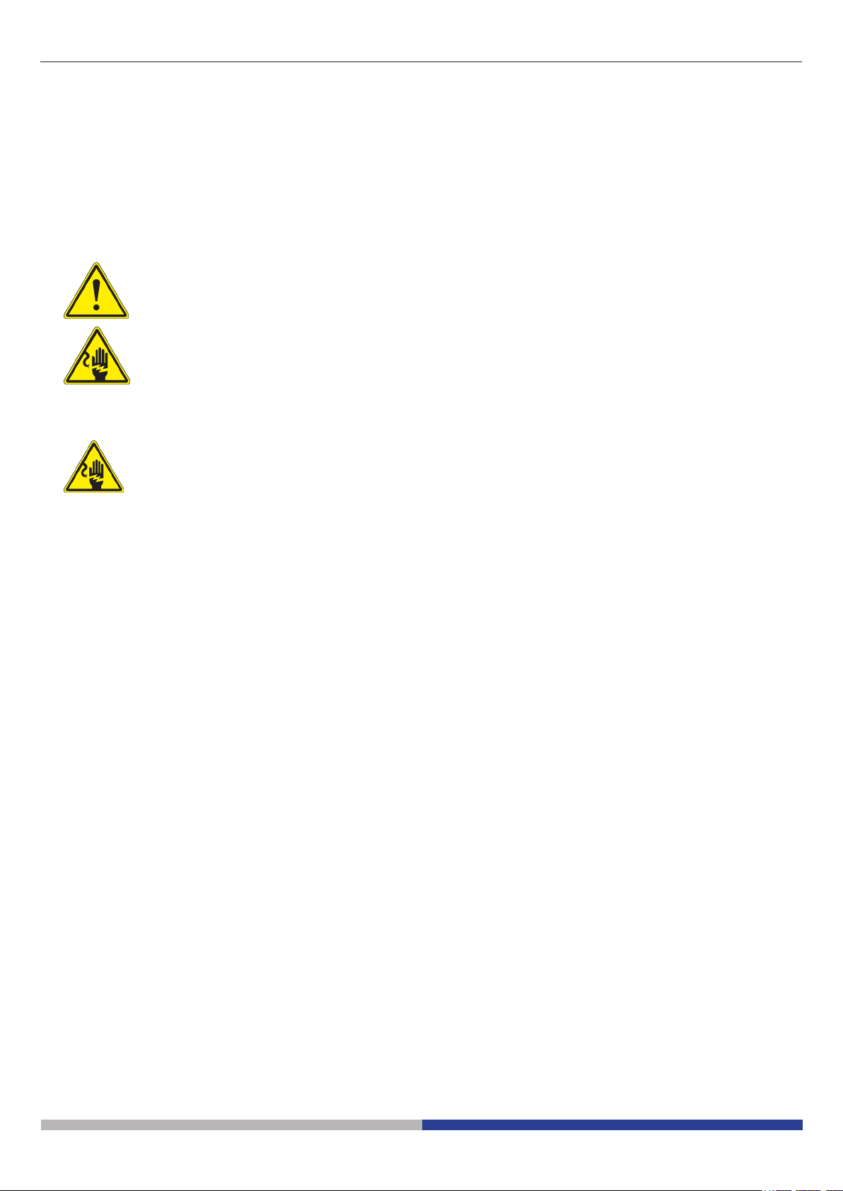
2. Symbols and conventions
The following chart is an illustrated glossary of the symbols that are used in this manual.
CAUTION
This symbol indicates a potential risk and alerts you to proceed with caution.
ELECTRICAL SHOCK
This symbol indicates a risk of electrical shock.
3. Safety Information
Avoiding Electrical Shock
Before plugging in the power supply, make sure that the supplying voltage of your region matches with the
operation voltage of the equipment and that the lamp switch is in o position. Users should observe all safety
regulations of the region. The equipment has acquired the CE safety label. However, users have full responsibility
to use this equipment safely. Please follow the guidelines below, and read this manual in its entirety to ensure
safe operation of the unit.
4. Intended use
For research and teaching use only. Not intended for any animal or human therapeutic or diagnostic use.
Page 3
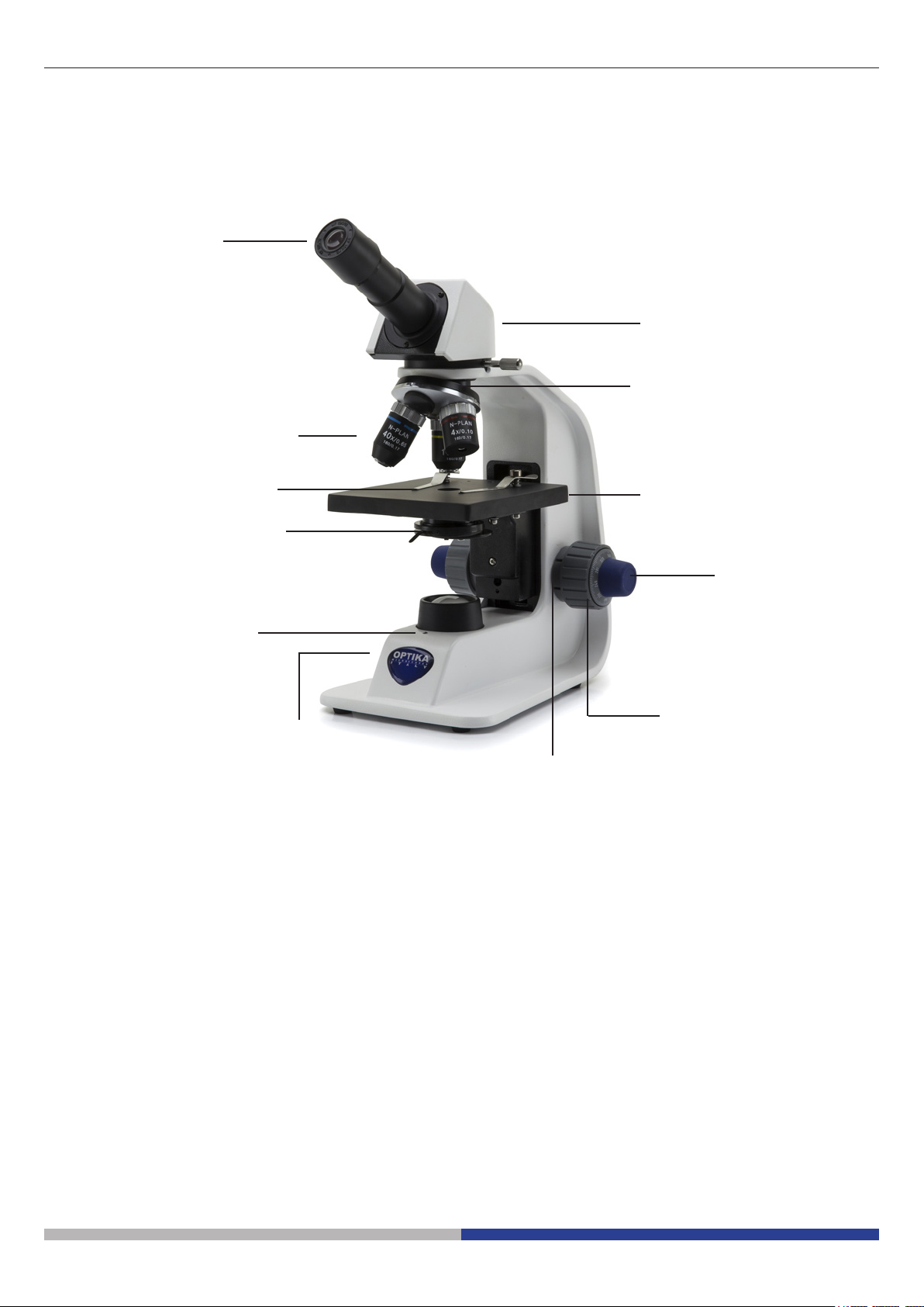
5. Overview
5.1 B-151 / B-151R-PL
EYEPIECE
OBJECTIVES
OBSERVATION
HEAD
NOSEPIECE
STAGE CLIPS
CONDENSER
LED CHARGE
INDICATOR
(ONLY “R”
VERSION)
MAIN SWITCH / INTENSITY
ADJUSTMENT DIAL
STAGE
FINE FOCUS
KNOB
COARSE
FOCUS KNOB
TENSION
ADJUSTMENT
COLLAR
Page 4
5.2 B-153 - B-155 - B-157 - B-159 /B-152R-PL -B-153R-PL -B-155R-PL -B-157R-PL -B-159R-PL
EYEPIECE
OBSERVATION HEAD
-) MONOCULAR (B-152 / B-153 / B-155)
-) BINOCULAR (B-157 / B-159)
NOSEPIECE
OBJECTIVES
SLIDE
HOLDER
CONDENSER
STAGE
FINE FOCUS
KNOB
LED CHARGE
INDICATOR
(ONLY “R”
VERSION)
MAIN SWITCH / INTENSITY
ADJUSTMENT DIAL
COARSE
FOCUS KNOB
TENSION
ADJUSTMENT
COLLAR
X/Y MOVEMENT
KNOBS
Page 5
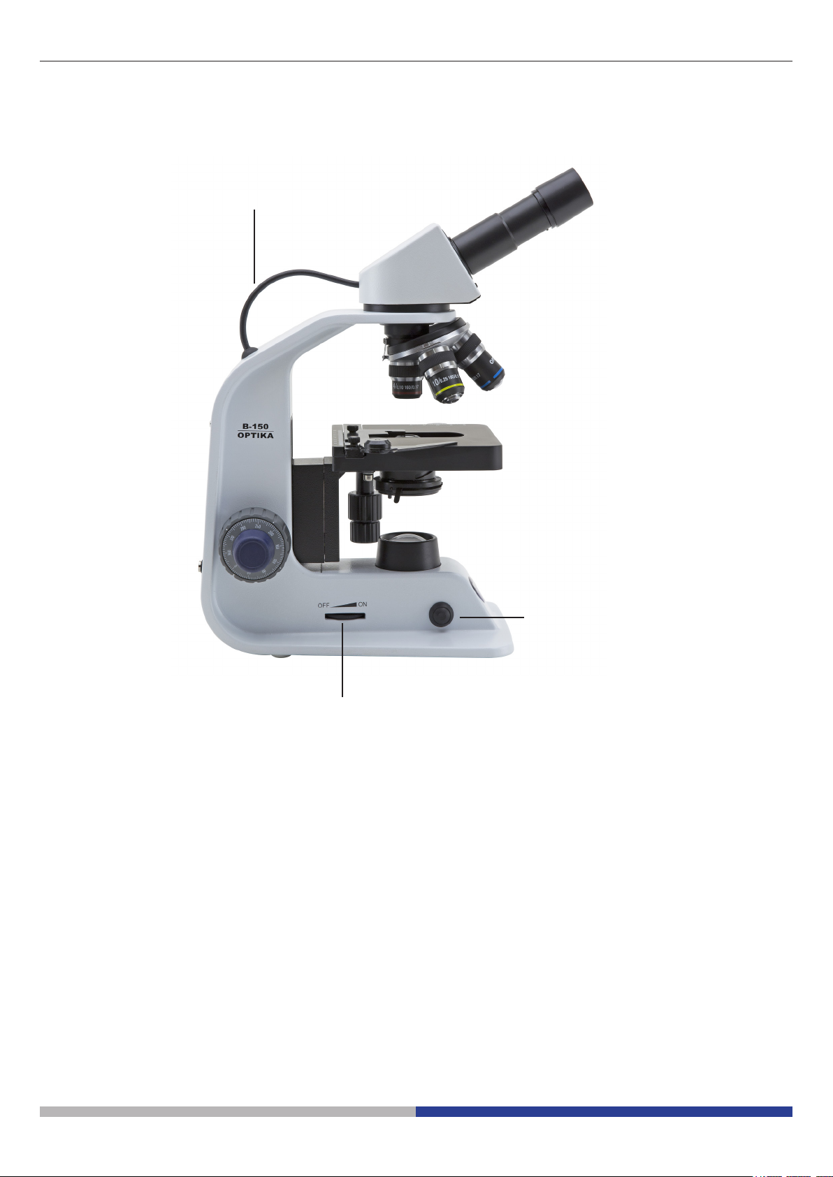
5.3 B-151ALC - B-153ALC - B-155ALC - B-157ALC - B-159ALC
ALC CONNECTION CABLE
MAIN SWITCH / INTENSITY
ADJUSTMENT DIAL
ALC ON/OFF BUTTON
Page 6
6. Unpacking
The microscope is housed in a moulded Styrofoam container. Remove the tape from the edge of the container
and lift the top half of the container. Take some care to avoid that the optical items (objectives and eyepieces)
fall out and get damaged. Using both hands (one around the arm and one around the base), lift the microscope
from the container and put it on a stable desk.
Do not touch with bare hands optical surfaces such as lenses, lters or glasses. Traces of grease or
other residuals may deteriorate the nal image quality and corrode the optics surface in a short time.
7. Assembling
Once opened the box, the microscope parts are the following:
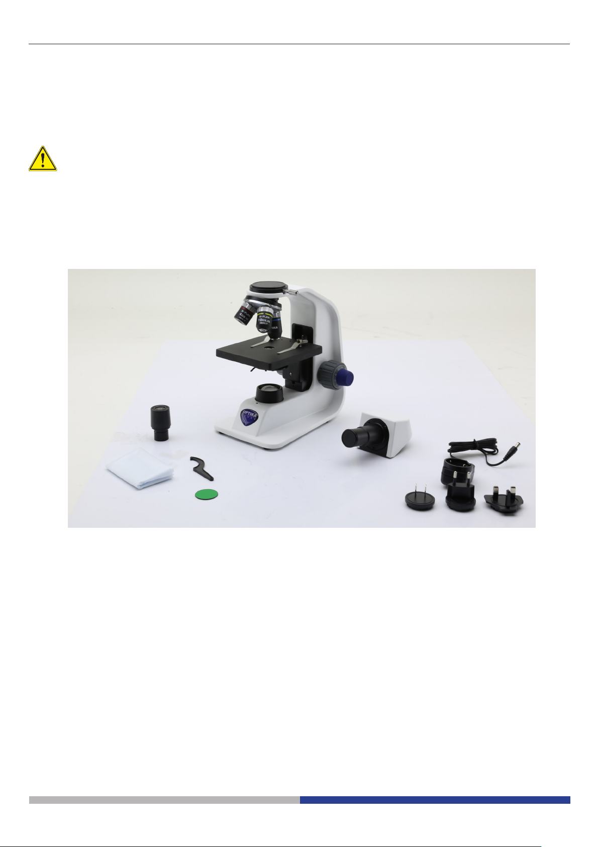
7.1 B-151 / B-151ALC / B-151R-PL
③
⑥
① Frame
② Monocular observation head
③ Eyepiece
④ Tension adjustment tool
⑤
⑦
①
②
④
⑧
⑤ Objectives (4X / 10X / 40X)
⑥ Dust cover
⑦ Green lter
⑧ Power supply
Page 7

7.2 B-152R-PL / B-153 / B-153ALC / B-153R-PL
③
⑥
① Frame
② Monocular observation head
③ Eyepiece
④ Tension adjustment tool
④
⑤
⑦
①
②
⑧
⑤ Objectives
B-152R-PL (4X / 10X / 40X)
B-153 (all) (4X / 10X / 40X / 60X)
⑥ Dust cover
⑦ Green lter
⑧ Power supply
7.3 B-155 / B-155ALC / B-155R-PL
③
⑥
⑦ ⑧
① Frame
② Monocular observation head
③ Eyepiece
④ Tension adjustment tool
⑤ Objectives (4X / 10X / 40X / 100X)
⑤
④
①
②
⑨
⑥ Dust cover
⑦ Green lter
⑧ Power supply
⑨ Immersion oil
Page 8
7.4 B-157 / B-157ALC / B-157R-PL
③
⑥
① Frame
② Binocular observation head
③ Eyepiece
④ Tension adjustment tool
⑤
④
①
②
⑦
⑧
⑤ Objectives (4X / 10X / 40X / 60X)
⑥ Dust cover
⑦ Green lter
⑧ Power supply
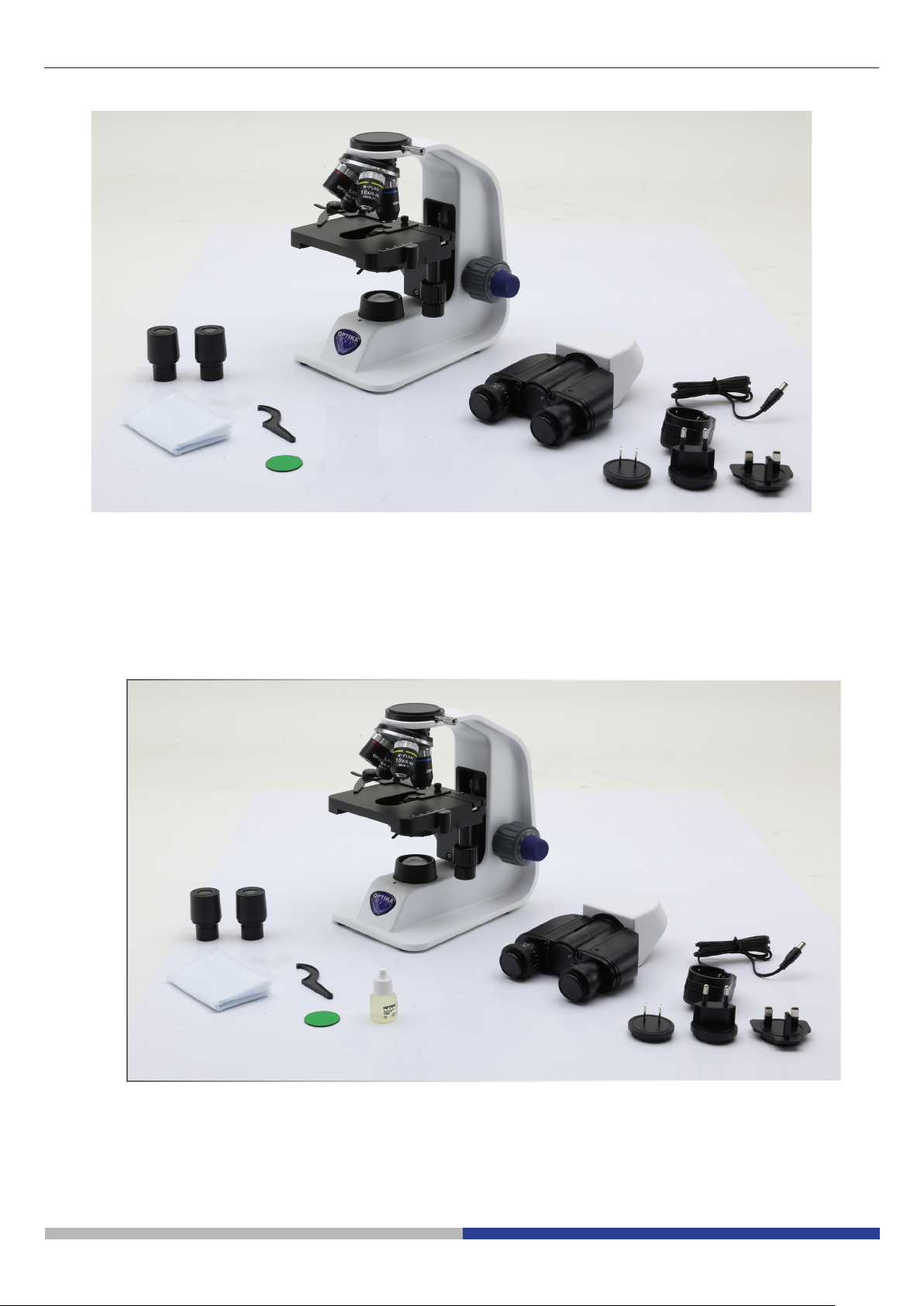
7.5 B-159 / B-159ALC / B-159R-PL
⑤
③
④
⑥
⑦
①
②
⑨
⑧
① Frame
② Binocular observation head
③ Eyepiece
④ Tension adjustment tool
⑤ Objectives (4X / 10X / 40X / 100X)
⑥ Dust cover
⑦ Green lter
⑧ Power supply
⑨ Immersion oil
Page 9
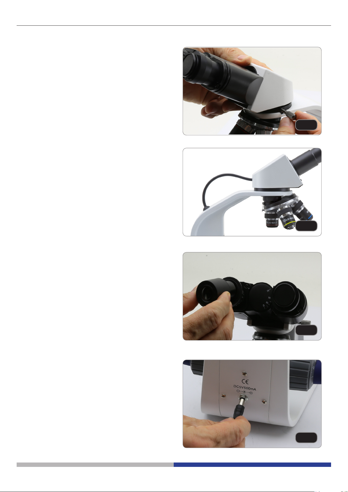
7.6 Assembling the microscope
1. Remove the dust cap from the microscope frame
and from the bottom of the observation head.
2. Insert the optical head above the stand and
tighten the screw. (Fig. 1)
• Hold the head with one hand during the locking in order to avoid that the head falls.
Only for ALC models:
3. Connect the cable of the ALC (Automatic Light Control) system to the socket placed on the observation head and on the back side of the frame. (Fig. 2)
Fig. 1
Fig. 2
4. Insert both eyepieces into the tubes of the optical
head. (Fig. 3)
• For models B-151, B-152, B-153 and B-155:
only one eyepiece is used as these models
are monocular.
5. Insert the power supply jack in the socket placed
at the rear side of the microscope. (Fig. 4)
Fig. 3
Page 10
Fig. 4
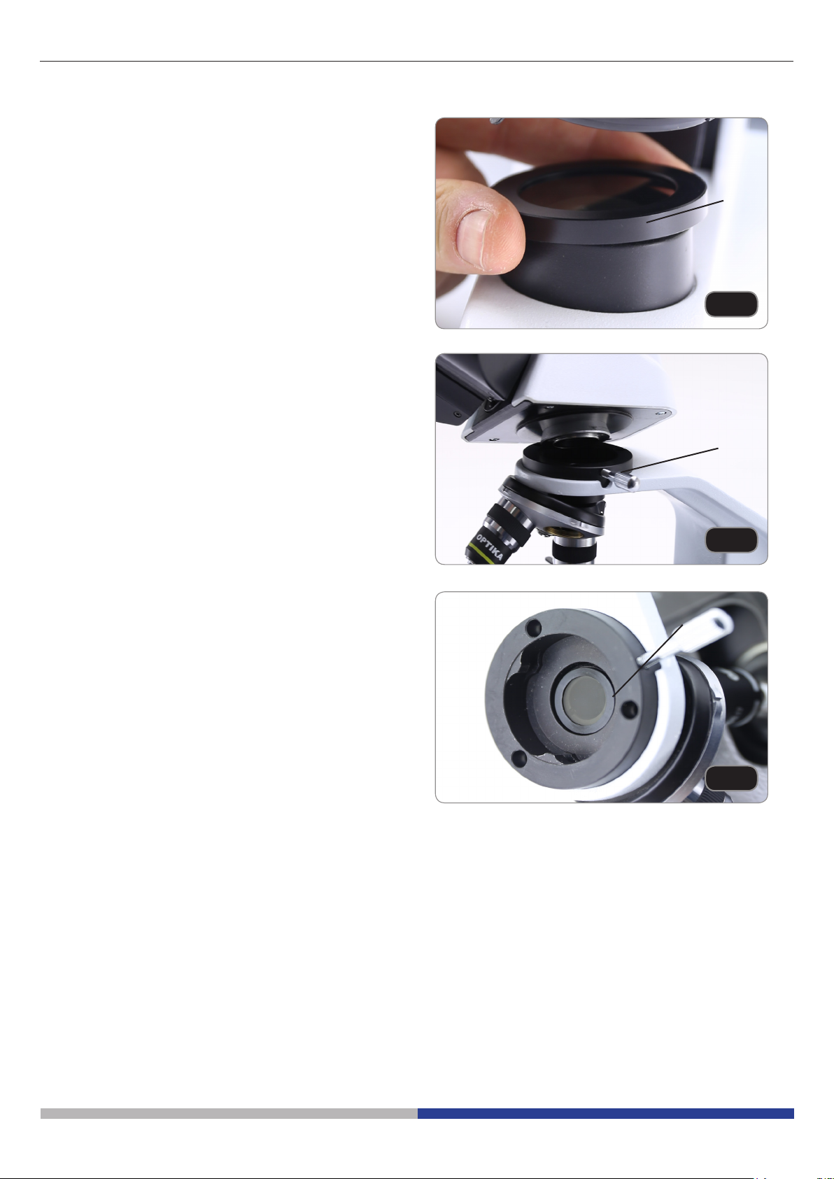
7.7 Polarizing set (optional)
1. Place the polarizer on the light exit ① at the base
of the microscope. (Fig. 5)
2. Loosen the head xing knob ② and remove the
head from the microscope frame. (Fig. 6)
①
Fig. 5
②
3. Insert the analyzer into the hole inside the frame
③. (Fig. 7)
4. Put back the head into its original position and
lock the xing knob.
Fig. 6
③
Fig. 7
Page 11
8. Use of the microscope
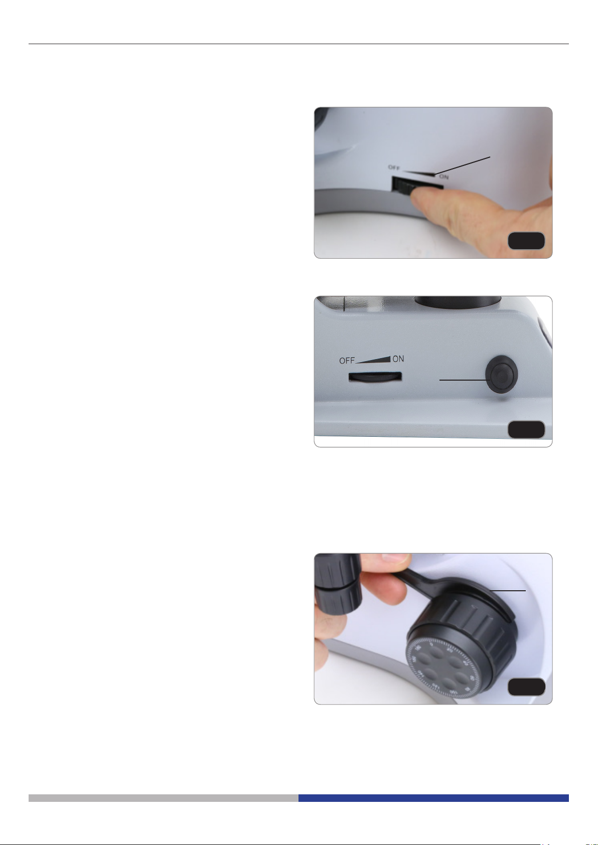
8.1 Light intensity adjustment
Operate on the light intensity adjustment dial to turn
ON / OFF the microscope and to increase / decrease
the illumination voltage ①. (Fig. 8)
8.2 Use of ALC system
1. Adjust the desired brightness through the eyepieces using the light intensity dial (chapter 8.1).
2. Press the ALC button ② to store this setting (Fig.
9). The light on the microscope will turn o for
some seconds, the will turn on again.
• The settings could not be working when the
light intensity is too low or too high. This is
not a defect.
3. Now the system will automatically adapt the
brightness to the eyepieces when an objective is
changed, when the aperture diaphragm is used
or when another specimen is placed on the stage.
4. Pressing the ALC button again, the ALC system
will be disabled.
• When ALC system is active the light intensity
dial is not active.
①
Fig. 8
②
Fig. 9
8.3 Coarse focus tension adjustment
• Adjust the tension using the provided tool.
The coarse knob tension is pre-setted in the factory.
To modify the tension according to personal’s needs,
rotate the ring ③ using the provided tool (Fig. 10).
Clockwise rotation increases the tension. If the tension is too loose, the stage could go lower by itself
or the focus easily lost after ne adjustment. In this
case, rotate the knob in order to increase the tension.
Page 12
③
Fig. 10
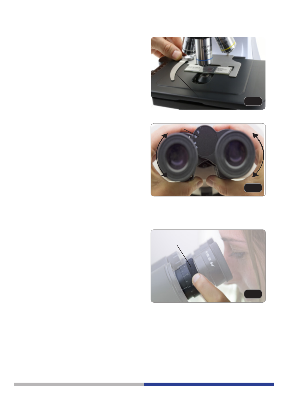
8.4 Stage
All models except B-151 series
Stage accepts standard slides 26 x 76 mm, thickness
1,2 mm with coverslide 0,17mm. (Fig. 11)
1. Open the spring arm of the slide holder ① and
place the slide from the front on the stage.
2. Gently release the spring arm of the slide holder.
• A sudden release of the spring arm could
cause the falling of the slide.
8.5 Adjust the interpupillary distance
This operation can be done only on binocular
models.
Hold the right and left parts of the observation head
using both hands and adjust the interpupillary distance by turning the two parts until one circle of light can
be seen. (Fig. 12)
• The graduation on the interpupillary distance indicator ②, pointed by the spot “.” on the eyepiece
holder, shows the distance between the operator’s eyes.
The range of the interpupillary distance is 48- 75 mm.
8.6 Diopter adjustment
This operation can be done only on binocular
models.
1. Look into the right eyepiece with your right eye
only, and focus on the specimen.
2. Look into the left eyepiece with your left eye
only. If the image is not sharp, use the dioptric
adjustment ring ③ to compensate. (Fig. 13)
③
②
①
Fig. 11
Fig. 12
• The adjustment range is ±5 diopter. The number indicated on the adjustment ring graduation should correspond to the operator’s dioptric correction.
Fig. 13
Page 13

8.7 Use of oil immersion objective
B-155 and B-159 models only
1. Focus the specimen with a low power objective.
2. Lower the stage.
3. Put a drop of oil (provided) on the area of the
specimen to be observed. (Fig. 14)
• Make sure that there are no oil bubbles. Air
bubbles in the oil damage the image quality.
• To check for bubbles: remove an eyepiece, fully open the aperture diaphragm and observe the
objective exit pupil. (The pupil must be circular
and bright).
• To remove the bubbles, gently move the nosepiece to the right and left to move the immersion
objective a few times and allow the air bubbles
to move.
4. Insert immersion objective.
5. Return the stage to the upper focusing point and
obtain an optimal focus using the ne focus knob.
6. After use, gently remove the oil with a soft paper
towel or a lightly moistened optic paper with a
mixture of ethyl ether (70%) and absolute ethyl
alcohol (30%).
• The immersion oil, if not immediately cleaned,
could crystallize creating a glass-like layer.
In this situation the observation of the speci-
menwouldbe dicult(evennotimpossible)
due to the presence of an additional thickness
on the objective.
Fig. 14
8.8 Aperture diaphragm
The Numerical Aperture (N.A.) value of the aperture
diaphragm aects the image contrast. Increasing or
reducing this value one can vary resolution, contrast
and depth of focus of the image.
Move the diaphragm lever ① (Fig. 15) toward left or
right to decrease or increase the N.A. value.
• With low contrast specimens set the numerical
aperture to about 70%-80% of the objective’s
N.A. If necessary, remove on eyepiece and, looking into empty sleeve, adjust the condenser’s
diaphragm in order to obtain an image like the
one in Fig. 16.
①
Fig. 15
IRIS DIAPHRAGM
70-80%
30-20%
Page 14
FIELD OF VIEW
Fig. 16

8.9 Use with rechargeable batteries
This operation can be done only with “R” models.
When the microscope is plugged with the power supply, the LED indicator for the battery recharge ① is
lit. (Fig. 17)
• LED red: battery under charge
• LED green: battery fully charged.
When the microscope is unplugged, the LED is o.
During the normal use with batteries, LED is always
OFF.
8.10 Use of the polarizer (optional)
1. Remove the specimen from the stage.
2. Looking inside the eyepieces, rotate the polarizer
until the darkest position is achieved.
3. Once the dark is achieved (“extinction” or “Crossed Nicol” position) it is possible to begin the
observation.
①
Fig. 17
Page 15

9. Maintenance
To think about when and after using the microscope
• The microscope should always be kept vertically when moving it and be careful so that no moving
parts, such as the eyepieces, fall out.
• Never mishandle or impose unnecessary force on the microscope.
• Never attempt to service the microscope yourself.
• After use, turn o the light immediately, cover the microscope with the provided dust-cover, and keep
it in a dry and clean place.
Electrical safety precautions
• Before plugging in the power supply, make sure that the supplying voltage of your region matches
with the operation voltage of the equipment and that the lamp switch is in o-position.
• Users should observe all safety regulations of the region. The equipment has acquired the CE
safety label. However, users do have full responsibility to use this equipment safely.
Cleaning the optics
• If the optical parts need to be cleaned try rst to: use compressed air.
• If that is not sucient: use a soft lint-free piece of cloth with water and a mild detergent.
• And as a nal option: use the piece of cloth moistened with a 3:7 mixture of ethanol and ether.
• Note: ethanol and ether are highly ammable liquids. Do not use them near a heat source, near sparks or
near electric equipment. Use these chemicals in a well ventilated room.
• Remember to never wipe the surface of any optical items with your hands. Fingerprints can damage the
optics.
• Do not disassemble objectives or eyepieces in attempt to clean them.
For the best results, use the OPTIKA cleaning kit (see catalogue).
If you need to send the microscope to Optika for maintenance, please use the original packaging.
Page 16

10. Troubleshooting
Review the information in the table below to troubleshoot operating problems.
PROBLEM CAUSE SOLUTION
I. Optical Section:
LED operates, but eld of view remains dark.
Dirt or dust is visible in the eld of
view.
Image looks double Aperture diaphragm is stopped
Visibility is poor.
• Image is not good.
• Contrast is poor.
• Details are indistinct.
• Image glares
One side of the image is out of focus. The nosepiece is not in the center
II. Mechanical Section:
The coarse focus knob is hard to
turn.
The focus is unstable. The tension adjustment collar is
III. Electric section
The LED doesn’t turn on. No power supply Check the power cord connection
The brightness is not enough The brightness adjustment is low Adjust the brightness
The light blinks The power cord is poorly con-
IV. Observation tube
Field of view of one eye does not
match that of the other.
Power supply is unplugged. Connect
Brightness is too low Set brightness to a proper level
Batteries are uncharged Fully charge the batteries
Dirt/dust on the specimen Clean the specimen
Dirt/dust on the eyepieces Clean the eyepieces
Open aperture diaphragm
down too far
Revolving nosepiece is in an
incorrect position
Aperture diaphragm is too closed
or to open
Dust or dirt on lenses (condenser,
objectives, eyepieces and slide)
of the light path
The specimen is out of place
(tilted)
The optical performance of the
sample cover glass is poor
The tension adjustment collar is
too tight
too loose
Batteries are uncharged Fully charge the batteries
nected
Interpupillary distance is incorrect. Adjust interpupillary distance.
Incorrect diopter adjustment. Adjust diopter.
Your view is not accustomed to
microscope observation.
Move the nosepiece to a click stop
Adjust aperture diaphragm
Clean thoroughly
Turn the nosepiece to a click stop
Place the specimen at on the stage.
Use a cover glass of better quality
Loosen the tension adjustment collar
Tighten the tension adjustment collar
Check the power cord
Upon looking into eyepieces, try looking at
overall field before concentrating on specimen range. You may also find it helpful to
look up and into distance for a moment
before looking back into microscope.
Page 17

Equipment disposal
Art.13 Dlsg 25 July 2005 N°151. “According to directives 2002/95/EC, 2002/96/EC and 2003/108/EC relating to
the reduction in the use of hazardous substances in electrical and electronic equipment and waste disposal.”
The basket symbol on equipment or on its box indicates that the product at the end of its useful life should be
collected separately from other waste. The separate collection of this equipment at the end of its lifetime is organized and managed by the producer. The user will have to contact the manufacturer and follow the rules that he
adopted for end-of-life equipment collection. The collection of the equipment for recycling, treatment and environmentally compatible disposal, helps to prevent possible adverse eects on the environment and health and
promotes reuse and/or recycling of materials of the equipment. Improper disposal of the product involves the
application of administrative penalties as provided by the laws in force.
Page 18

OPTIKA S.r.l.
®
®
Via Rigla, 30 - 24010 Ponteranica (BG) - ITALY Tel.: +39 035.571.392
info@optikamicroscopes.com - www.optikamicroscopes.com
OPTIKA Spain
spain@optikamicroscopes.com
OPTIKA USA
usa@optikamicroscopes.com
OPTIKA China
china@optikamicroscopes.com
OPTIKA India
india@optikamicroscopes.com
OPTIKA Central America
camerica@optikamicroscopes.com
®
®
®
®
®
®
®
®
®
®

Serie B-150
Serie B-150R-PL (B-151R-PL / B-152R-PL / B-153R-PL / B-155R-PL / B-157R-PL / B-159R-PL)
MANUALE DI ISTRUZIONI
Modelli
Serie B-150 (B-151 / B-153 / B-155 / B-157 / B-159)
Serie B-150 ALC (B-151ALC / B-153ALC / B-155ALC / B-157ALC / B-159ALC)
Ver. 10.0 2019

Sommario
1. Avvertenza 22
2. Simboli 22
3. Informazioni sulla sicurezza 22
4. Utilizzo previsto 22
5. Descrizione dello strumento 23
5.1 B-151 / B-151R-PL 23
5.2 B-153 - B-155 - B-157 - B-159 / B-152R-PL -B-153R-PL -B-155R-PL -B-157R-PL -B-159R-PL 24
5.3 B-151ALC - B-153ALC - B-155ALC - B-157ALC - B-159ALC 25
6. Disimballaggio 26
7. Assemblaggio 26
7.1 B-151 / B-151ALC / B-151R-PL 26
7.2 B-152R-PL / B-153 / B-153ALC / B-153R-PL 27
7.3 B-155 / B-155ALC / B-155R-PL 27
7.4 B-157 / B-157ALC / B-157R-PL 28
7.5 B-159 / B-159ALC / B-159R-PL 28
7.6 Procedura di assemblaggio 29
7.7 Set di polarizzazione (opzionale) 30
8. Uso del microscopio 31
8.1 Regolazione intensità luminosa 31
8.2 Uso del sistema ALC 31
8.3 Regolazione della frizione 31
8.4 Tavolino 32
8.5 Regolazione distanza interpupillare 32
8.6 Regolazione diottrica 32
8.7 Uso di obiettivi ad immersione 33
8.8 Diaframma di apertura 33
8.9 Uso con batterie ricaricabili 34
8.10 Uso con polarizzatore (opzionale) 34
9. Manutenzione 35
10. Risoluzione dei problemi 36
Smaltimento 37
Pagina 21

1. Avvertenza
Questo microscopio è uno strumento scientico di alta precisione, progettato per durare a lungo con una minima
manutenzione; la realizzazione è secondo i migliori standard ottici e meccanici, per poter essere utilizzato
quotidianamente. Vi ricordiamo che questo manuale contiene informazioni importanti per la sicurezza e per la
manutenzione dello strumento, e deve quindi essere messo a disposizione di coloro che lo utilizzeranno.
Decliniamo ogni responsabilità derivante da un utilizzo dello strumento non indicato nel presente manuale.
2. Simboli
La seguente tabella riporta i simboli utilizzati in questo manuale.
PERICOLO
Questo simbolo indica un rischio potenziale ed avverte di procedere con cautela.
SHOCK ELETTRICO
Questo simbolo indica un rischio di shock elettrico.
3. Informazioni sulla sicurezza
Per evitare shock elettrici
Prima di collegare il cavo di alimentazione alla presa elettrica, assicurarsi che il voltaggio della rete locale
coincida con il voltaggio dello strumento e che l’interruttore dell’illuminazione sia nella posizione “OFF”.
Gli utenti dovranno seguire tutte le norme di sicurezza locali. Lo strumento è certicato CE. In ogni caso, gli
utilizzatori sono gli unici responsabili per un utilizzo sicuro dello strumento. Per l’utilizzo in sicurezza dello
strumento è importante attenersi alle seguenti istruzioni e leggere il manuale in tutte le sue parti.
4. Utilizzo previsto
Solo per applicazioni di ricerca ed usi didattici. Non indicato per utilizzo diagnostico e terapeutico umano e
veterinario.
Pagina 22

5. Descrizione dello strumento
5.1 B-151 / B-151R-PL
OCULARE
OBIETTIVI
MOLLETTINE
FERMACAMPIONE
CONDENSATORE
TESTA DI
OSSERVAZIONE
REVOLVER
TAVOLINO
LED INDICATORE
DI CARICA
(SOLO VERSIONE
“R”)
INTERRUTTORE / MANOPOLA
REGOLAZIONE INTENSITÀ
MANOPOLA
MICROMETRICA
DI MESSA A FUOCO
MANOPOLA
MACROMETRICA
DI MESSA A FUOCO
ANELLO
REGOLAZIONE
TENSIONE
Pagina 23

5.2 B-153 - B-155 - B-157 - B-159 / B-152R-PL -B-153R-PL -B-155R-PL -B-157R-PL -B-159R-PL
OCULARE
TESTA DI OSSERVAZIONE
-) MONOCULARE (B-152 / B-153 / B-155)
-) BINOCULARE (B-157 / B-159)
REVOLVER
OBIETTIVI
FERMAVETRINO
TAVOLINO
CONDENSATORE
LED INDICATORE
DI CARICA
(SOLO VERSIONE
“R”)
INTERRUTTORE / MANOPOLA
REGOLAZIONE INTENSITÀ
MANOPOLA
MICROMETRICA
DI MESSA A FUOCO
MANOPOLA
MACROMETRICA
DI MESSA A FUOCO
ANELLO
REGOLAZIONE
TENSIONE
MANOPOLE
TRASLAZIONE X/Y
Pagina 24

5.3 B-151ALC - B-153ALC - B-155ALC - B-157ALC - B-159ALC
CAVO DI COLLEGAMENTO
ALC
INTERRUTTORE / MANOPOLA
REGOLAZIONE INTENSITÀ
TASTO ON/OFF
SISTEMA ALC
Pagina 25

6. Disimballaggio
Il microscopio si trova in un imballaggio di polistirolo espanso stampato. Dopo aver tolto il nastro adesivo da tutti
gli imballi, sollevare la metà superiore dell’imballaggio. Fare attenzione a non far cadere o danneggiare i componenti ottici (obiettivi e oculari). Estrarre il microscopio dal suo imballaggio con entrambe le mani (una intorno
al braccio e una intorno alla base) e appoggiarlo su un piano stabile.
Non toccare a mani nude superfici ottiche come lenti, filtri o vetri. Tracce di grasso o altri residui possono deteriorare la qualità dell’immagine nale e corrodere la supercie dell’ottica in breve tempo.
7. Assemblaggio
Una volta aperto l’imballo, le parti del microscopio sono le seguenti:
7.1 B-151 / B-151ALC / B-151R-PL
⑤
③
⑥
⑦
① Stativo
② Testa di osservazione monoculare
③ Oculare
④ Chiave regolazione tensione
①
②
④
⑧
⑤ Obiettivi (4X / 10X / 40X)
⑥ Copertina
⑦ Filtro verde
⑧ Alimentatore
Pagina 26

7.2 B-152R-PL / B-153 / B-153ALC / B-153R-PL
③
④
⑥
① Stativo
② Testa di osservazione monoculare
③ Oculare
④ Chiave regolazione tensione
⑤
⑦
①
②
⑧
⑤ Obiettivi
B-152R-PL (4X / 10X / 40X)
B-153 (tutti) (4X / 10X / 40X / 60X)
⑥ Copertina
⑦ Filtro verde
⑧ Alimentatore
7.3 B-155 / B-155ALC / B-155R-PL
③
⑥
⑦ ⑧
① Stativo
② Testa di osservazione monoculare
③ Oculare
④ Chiave regolazione tensione
⑤ Obiettivi (4X / 10X / 40X / 100X)
⑤
④
①
②
⑨
⑥ Copertina
⑦ Filtro verde
⑧ Alimentatore
⑨ Olio da immersione
Pagina 27

7.4 B-157 / B-157ALC / B-157R-PL
③
⑥
① Stativo
② Testa di osservazione binoculare
③ Oculare
④ Chiave regolazione tensione
⑤
④
①
②
⑦
⑤ Obiettivi (4X / 10X / 40X / 60X)
⑥ Copertina
⑦ Filtro verde
⑧ Alimentatore
7.5 B-159 / B-159ALC / B-159R-PL
⑤
③
④
⑥
⑦
①
②
⑨
⑧
① Stativo
② Testa di osservazione binoculare
③ Oculare
④ Chiave regolazione tensione
⑤ Obiettivi (4X / 10X / 40X / 100X)
⑥ Copertina
⑦ Filtro verde
⑧ Alimentatore
⑨ Olio da immersione
Pagina 28

7.6 Procedura di assemblaggio
1. Rimuovere il tappo di protezione dallo stativo e
dalla parte sottostante della testa di osservazio-
ne.
2. Inserire la testa sullo stativo e serrare la vite di
ssaggio. (Fig. 1)
• Tenere sempre la testata con una mano durante il serraggio della vite per evitare che la
stessa cada.
Solo per i modelli ALC:
3. Collegare il cavo di connesssione del sistema
ALC (Automatic Light Control) ai connettori posti sul retro della testa e dello stativo. (Fig. 2)
Fig. 1
4. Inserire gli oculari nei portaoculari vuoti della testa di osservazione. (Fig. 3)
• Per i modelli B-151, B-152, B-153 e B-155: viene usato un solo oculare perchè questi modelli sono monoculari.
5. Inserire lo spinotto dell’alimentatore nel connettore posto sul retro del microscopio. (Fig. 4)
Fig. 2
Fig. 3
Pagina 29
Fig. 4

7.7 Set di polarizzazione (opzionale)
1. Posizionare il polarizzatore ① sulla lente di campo del microscopio. (Fig. 5)
2. Allentare la manopola di ssaggio della testa ②
e rimuovere la testa di osservazione dallo stativo.
(Fig. 6)
①
Fig. 5
②
3. Inserire l’analizzatore nella sede all’interno dello
stativo ③. (Fig. 7)
4. Riposizionare la testa e serrare le manopola di
bloccaggio.
Fig. 6
③
Fig. 7
Pagina 30

8. Uso del microscopio
8.1 Regolazione intensità luminosa
Agire sulla rotellina di regolazione dell’intensità luminosa per accendere e spegnere lo strumento e per
aumentare o diminuire il voltaggio dell’illuminazione
①. (Fig. 8)
8.2 Uso del sistema ALC
1. Regolare la luminosità desiderata agli oculari
usando la rotellina di regolazione dell’intensità lu-
minosa (parag. 8.1).
2. Premere il tasto ALC ② per memorizzare questa
impostazione (Fig. 9). La luce al microscopio si
spegne per qualche secondo, poi si riaccende.
• Il settaggio della luminosità potrebbe non an-
dareabuonneselaluminositàimpostataè
troppo bassa o troppo alta. Questo non è un
difetto.
3. Ora il sistema adatterà automaticamente la luminosità agli oculari quando si cambia obiettivo,
quando si agisce sul diaframma di apertura o
quando si utilizza un campione diverso.
4. Premendo nuovamente il tasto ALC, il sistema
viene disattivato.
• Quando il sistema ALC è attivo la rotella di regolazione della luminosità non è attiva.
①
Fig. 8
②
Fig. 9
8.3 Regolazione della frizione
• Regolare la frizione della manopola utilizzando l’apposita ghiera.
La frizione della manopola macrometrica di messa a
fuoco è preregolata in fabbrica.
Per modicare la tensione in base alle preferenze
personali ruotare la ghiera ③ utilizzando la chiavetta
in dotazione (Fig. 10).
La rotazione in senso orario aumenta la frizione. La
tensione è troppo bassa se il tavolino scende da solo
per gravità o se il fuoco si perde facilmente dopo una
regolazione con la manopola micrometrica. In questo
caso aumentare la tensione ruotando la ghiera.
Pagina 31
③
Fig. 10

8.4 Tavolino
Tutti i modelli tranne la serie B-151
Il tavolino accetta vetrini standard 26 x 76 mm, spessore 1,2 mm con coprioggetto 0,17mm. (Fig. 11)
1. Allargare il braccio movibile del fermapreparati ①
e posizionare frontalmente i vetrini sul tavolino.
2. Rilasciare delicatamente il braccio movibile del
fermapreparati.
• Un rilascio brusco del fermapreparati potrebbe comportare la caduta del vetrino.
8.5 Regolazione distanza interpupillare
①
Fig. 11
Questa operazione viene eseguita solo sui modelli binoculari.
Osservando con entrambi gli occhi, sostenere il
gruppo di oculari. Ruotare questi lungo l’asse comune no ad ottenere un unico campo visivo. (Fig. 12)
• La scala graduata sull’indicatore della distanza
interpupillare ②, indicata dal puntino “.” sul por-
taoculare, mostra la distanza interpupillare dell’o-
peratore.
Il range di distanza interpupillare è 48- 75 mm.
8.6 Regolazione diottrica
Questa operazione viene eseguita solo sui modelli binoculari.
1. Osservare e mettere a fuoco il preparato guardando con l’occhio destro attraverso l’oculare destro utilizzando le manopole di messa a fuoco del
microscopio.
2. Ora guardare attraverso l’oculare sinistro con
l’occhio sinistro. Se l’immagine non è nitida, agire
sulla compensazione diottrica utilizzando l’apposito anello ③. (Fig. 13)
• Il range di compensazione è di ±5 diottrie. Il
numero indicato sulla scala presente sull’anello di compensazione dovrebbe corrispondere alla correzione diottrica dell’operatore.
②
Fig. 12
③
Fig. 13
Pagina 32

8.7 Uso di obiettivi ad immersione
Solo modelli B-155 e B-159
1. Mettere a fuoco con un obiettivo a basso ingrandimento.
2. Abbassare il tavolino.
3. Mettere una goccia di olio (in dotazione) sulla
zona del campione da osservare. (Fig. 14)
• Assicurarsi che non ci siano bolle d’aria. Le
bolle d’aria nell’olio danneggiano la qualità
dell’immagine.
• Per vericare la presenza di bolle: rimuovere un
oculare, aprire completamente il diaframma di
apertura e osservare la pupilla di uscita dell’obiettivo. (La pupilla deve essere rotonda e lumi-
nosa).
• Per rimuovere le bolle, muovere delicatamente il
revolver a destra e a sinistra per spostare alcune
volte l’obiettivo ad immersione e permettere alle
bolle d’aria di spostarsi.
4. Inserire l’obiettivo ad immersione.
5. Riportare in alto il tavolino e mettere a fuoco con
la manopola micrometrica.
6. Dopo l’uso rimuovere l’eccesso di olio con un
panno soce o con una cartina ottica umettata
con alcool (30%) ed etere etilico (70%).
• L’olio da immersione, se non pulito immediatamente, potrebbe cristallizzare creando uno strato simile a vetro.
In questa situazione l’osservazione del preparato risulterebbe dicile se non impossibile a causa della presenza di uno spessore
addizionale sull’obiettivo.
Fig. 14
8.8 Diaframma di apertura
Il valore di apertura numerica (A.N.) del diaframma
di apertura inuenza il contrasto dell’immagine. Aumentando o diminuendo questo valore in funzione
dell’apertura numerica dell’obiettivo si variano risoluzione, contrasto e profondità di campo dell’immagine
Spostare la leva del diaframma ① (Fig. 15) verso
destra o verso sinistra per aumentare o diminuire il
valore della A.N.
• Per campioni con basso contrasto impostare il
valore dell’apertura numerica a circa il 70%-80%
dell’A.N. dell’obiettivo. Se necessario, rimuovere
un oculare e, guardando nel portaoculare vuoto,
regolare la ghiera del condensatore no ad ottenere un’immagine come quella di Fig. 16.
①
Fig. 15
DIAFRAMMA AD IRIDE
70-80%
30-20%
Pagina 33
CAMPO VISIVO
Fig. 16

8.9 Uso con batterie ricaricabili
Questa operazione viene eseguita solo sui modelli “R”.
Quando il microscopio è collegato all’alimentatore, il
LED indicatore della ricarica delle batterie ① si ac-
cende. (Fig. 17)
• LED rosso: batteria in ricarica
• LED verde: batteria carica.
Quando il microscopio è scollegato, il LED è spento.
Durante il normale uso con sole batterie il LED è
sempre spento.
8.10 Uso con polarizzatore (opzionale)
1. Rimuovere il campione dal tavolino.
2. Guardando all’interno degli oculari, ruotare il po-
larizzatore no ad ottenere il buio completo agli
oculari.
3. Una volta ottenuto il buio (posizione di “estinzione” o di Nicol incrociati”) è possibile iniziare l’osservazione.
①
Fig. 17
Pagina 34

9. Manutenzione
Prima e dopo l’utilizzo del microscopio
• Tenere il microscopio sempre in posizione verticale quando lo si sposta.
• Assicurarsi inoltre che le parti mobili, ad esempio gli oculari, non cadano.
• Non maneggiare senza precauzioni e non adoperare inutile forza sul microscopio.
• Non cercare di provvedere da soli alla riparazione.
• Dopo l’uso spegnere immediatamente la lampada, coprire il microscopio con l’apposita copertina
antipolvere in dotazione e tenerlo in un luogo asciutto e pulito.
Precauzioni per un utilizzo sicuro
• Prima di collegare l’alimentatore alla rete elettrica assicurarsi che il voltaggio locale sia idoneo a
quello dell’apparecchio e che l’interruttore della lampada sia posizionato su “0”.
• Attenersi a tutte le precauzioni di sicurezza della zona in cui ci si trova ad operare
Pulizia delle ottiche
• Qualora le ottiche necessitino di essere pulite, utilizzare prima di tutto aria compressa.
• Se questo non fosse suciente usare un panno non slacciato, inumidito con acqua e un detergente deli
cato.
• Come ultima opzione è possibile usare un panno inumidito con una soluzione 3:7 di alcol etilico ed etere.
• Attenzione: l’alcol etilico e l’etere sono sostanze altamente inammabili. Non usarle vicino ad una fonte
di calore, a scintille o presso apparecchiature elettriche. Le sostanze devono essere adoperate in un luogo
ben ventilato.
• Non stronare la supercie di nessun componente ottico con le mani. Le impronte digitali possono danneggiare le ottiche.
• Non smontare gli obiettivi o gli oculari per cercare di pulirli.
Per un migliore risultato, utilizzare il kit di pulizia OPTIKA (vedi catalogo).
Se si necessita di spedire il microscopio al produttore per la manutenzione, si prega di utilizzare l’imballo originale.
Pagina 35

10. Risoluzione dei problemi
Consultare le informazioni riportate nella tabella seguente per risolvere eventuali problemi operativi.
PROBLEMA CAUSA SOLUZIONE
I. Sezione Ottica:
Il microscopio è acceso, ma il campo
visivo è scuro.
Nel campo visivo si osservano
sporco e polvere.
L’immagine appare sdoppiata Diaframma di apertura troppo
Bassa qualità dell’immagine.
• Immagine non buona.
• Basso contrasto.
• Dettagli non nitidi.
• Riessi nell’immagine
Un lato dell’immagine non è a fuoco. Il revolver è in una posizione non
II. Sezione Meccanica:
La manopola macrometrica è dicile
da ruotare
La messa a fuoco è instabile L’anello di regolazione della ten-
III. Sezione Elettrica
Il LED non si accende. Lo strumento non viene alimentato Vericare il collegamento del cavo di ali-
La luminosità è insuciente La luminosità è regolata bassa Regolare la luminosità
La luce lampeggia Il cavo di alimentazione non è col-
IV. Tubo di Osservazione
Il campo visivo è diverso per ciascun
occhio.
L’alimentatore è scollegato. Collegarlo
La luminosità è troppo bassa Regolarla ad un livello adeguato
Batterie scariche Caricare le batterie
Sporco e polvere sul campione Pulire il campione
Sporco e polvere sull’oculare Pulire l’oculare
Aprire un poco il diaframma
chiuso
Il revolver è in una posizione non
corretta
Diaframma di apertura troppo
chiuso
Le lenti (oculari e obiettivi) sono
sporche
corretta
Il campione non è ben posizionato
(inclinato)
La qualità ottica del vetrino portapreparato è scarsa
L’anello di regolazione della tensione è troppo stretto
sione è troppo allentato
Batterie scariche Caricare le batterie
legato bene
La distanza interpupillare non è
corretta
La correzione diottrica non è
giusta
La tecnica di visione non è corretta, e l’operatore sforza la vista
Ruotare il revolver no al clic
Aprire un poco il diaframma
Pulire accuratamente tutte le componenti
ottiche
Ruotare il revolver no al clic
Posizionare in piano il campione sul tavolino.
Utilizzare un vetrino di migliore qualità
Allentare l’anello di regolazione della ten-
sione
Stringere l’anello di regolazione della ten-
sione
mentazione
Vericare il collegamento del cavo
Regolare la distanza interpupillare
Regolare la correzione diottrica
Quando guarda il campione non focalizzi
lo sguardo in un unico punto ma guardi
l’intero campo visivo a disposizione. Periodicamente distolga lo sguardo e guardi un
punto distante, dopodichè torni ad analizzare il campione.
Pagina 36

Smaltimento
Ai sensi dell’articolo 13 del decreto legislativo 25 luglio 2005 n°151. “Attuazione delle direttive 2002/95/CE,
2002/96/CE e 2003/108/CE, relative alla riduzione dell’uso di sostanze pericolose nelle apparecchiature elettriche
ed elettroniche, nonché allo smaltimento dei riuti”.
Il simbolo del cassonetto riportato sulla apparecchiatura o sulla sua confezione indica che il prodotto alla ne della propria vita utile deve essere raccolto separatamente degli altri riuti. La raccolta dierenziata della presente
apparecchiatura giunta a ne vita è organizzata e gestita dal produttore. L’utente che vorrà disfarsi della presente
apparecchiatura dovrà quindi contattare il produttore e seguire il sistema che questo ha adottato per consentire
la raccolta separata dell’apparecchiatura giunta a ne vita. L’adeguata raccolta dierenziata per l’avvio successivo della apparecchiatura dismessa al riciclaggio, al trattamento e allo smaltimento ambientalmente compatibile
contribuisce ad evitare possibili eetti negativi sull’ambiente e sulla salute e favorisce il reimpiego e/o riciclo dei
materiali di cui è composta l’apparecchiatura. Lo smaltimento abusivo del prodotto da parte del detentore comporta l’applicazione delle sanzioni amministrative previste dalla normativa vigente.
Pagina 37

OPTIKA S.r.l.
®
Via Rigla, 30 - 24010 Ponteranica (BG) - ITALY Tel.: +39 035.571.392
info@optikamicroscopes.com - www.optikamicroscopes.com
'LVWULEXWHGE\
100 Lauman Lane, Suite A, Hicksville, NY 11801
Tel: (877) 877-7274 | Fax: (516) 801-2046
Email: Info@nyscopes.com
www.microscopeinternational.com
OPTIKA Spain
®
spain@optikamicroscopes.com
OPTIKA USA
®
usa@optikamicroscopes.com
OPTIKA China
®
china@optikamicroscopes.com
OPTIKA India
®
india@optikamicroscopes.com
OPTIKA Central America
®
camerica@optikamicroscopes.com
 Loading...