

Optika B-155, B-150, B-151, B-150R-PL, B-157 Instruction Manual
...
B-150 Series
B-150R-PL series (B-151R-PL / B-152R-PL / B-153R-PL / B-155R-PL / B-157R-PL / B-159R-PL)
INSTRUCTION MANUAL
Model
B-150 series (B-151 / B-153 / B-155 / B-157 / B-159)
B-150 ALC series (B-151ALC / B-153ALC / B-155ALC / B-157ALC / B-159ALC)
Ver. 10.0 2019

Summary
1. Warning 3
2. Symbols and conventions 3
3. Safety Information 3
4. Intended use 3
5. Overview 4
5.1 B-151 / B-151R-PL 4
5.2 B-153 - B-155 - B-157 - B-159 /B-152R-PL -B-153R-PL -B-155R-PL -B-157R-PL -B-159R-PL 5
5.3 B-151ALC - B-153ALC - B-155ALC - B-157ALC - B-159ALC 6
6. Unpacking 7
7. Assembling 7
7.1 B-151 / B-151ALC / B-151R-PL 7
7.2 B-152R-PL / B-153 / B-153ALC / B-153R-PL 8
7.3 B-155 / B-155ALC / B-155R-PL 8
7.4 B-157 / B-157ALC / B-157R-PL 9
7.5 B-159 / B-159ALC / B-159R-PL 9
7.6 Assembling the microscope 10
7.7 Polarizing set (optional) 11
8. Use of the microscope 12
8.1 Light intensity adjustment 12
8.2 Use of ALC system 12
8.3 Coarse focus tension adjustment 12
8.4 Stage 13
8.5 Adjust the interpupillary distance 13
8.6 Diopter adjustment 13
8.7 Use of oil immersion objective 14
8.8 Aperture diaphragm 14
8.9 Use with rechargeable batteries 15
8.10 Use of the polarizer (optional) 15
9. Maintenance 16
10. Troubleshooting 18
Equipment disposal 18
Page 2
1. Warning
This microscope is a scientic precision instrument designed to last for many years with a minimum of
maintenance. It is built to high optical and mechanical standards and to withstand daily use. We remind you
that this manual contains important information on safety and maintenance, and that it must therefore be made
accessible to the instrument users. We decline any responsibility deriving from incorrect instrument use uses
that does not comply with this manual.
2. Symbols and conventions
The following chart is an illustrated glossary of the symbols that are used in this manual.
CAUTION
This symbol indicates a potential risk and alerts you to proceed with caution.
ELECTRICAL SHOCK
This symbol indicates a risk of electrical shock.
3. Safety Information
Avoiding Electrical Shock
Before plugging in the power supply, make sure that the supplying voltage of your region matches with the
operation voltage of the equipment and that the lamp switch is in o position. Users should observe all safety
regulations of the region. The equipment has acquired the CE safety label. However, users have full responsibility
to use this equipment safely. Please follow the guidelines below, and read this manual in its entirety to ensure
safe operation of the unit.
4. Intended use
For research and teaching use only. Not intended for any animal or human therapeutic or diagnostic use.
Page 3
5. Overview
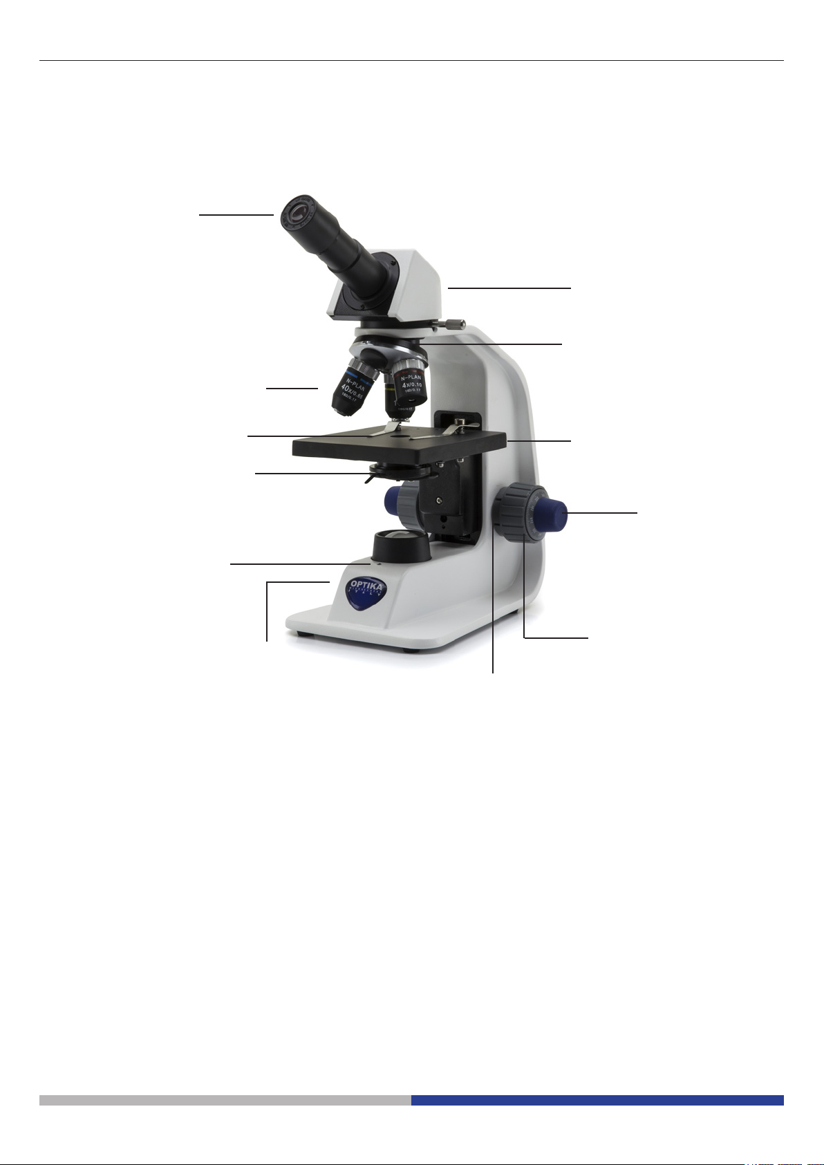
5.1 B-151 / B-151R-PL
EYEPIECE
OBJECTIVES
OBSERVATION
HEAD
NOSEPIECE
STAGE CLIPS
CONDENSER
LED CHARGE
INDICATOR
(ONLY “R”
VERSION)
MAIN SWITCH / INTENSITY
ADJUSTMENT DIAL
STAGE
FINE FOCUS
KNOB
COARSE
FOCUS KNOB
TENSION
ADJUSTMENT
COLLAR
Page 4
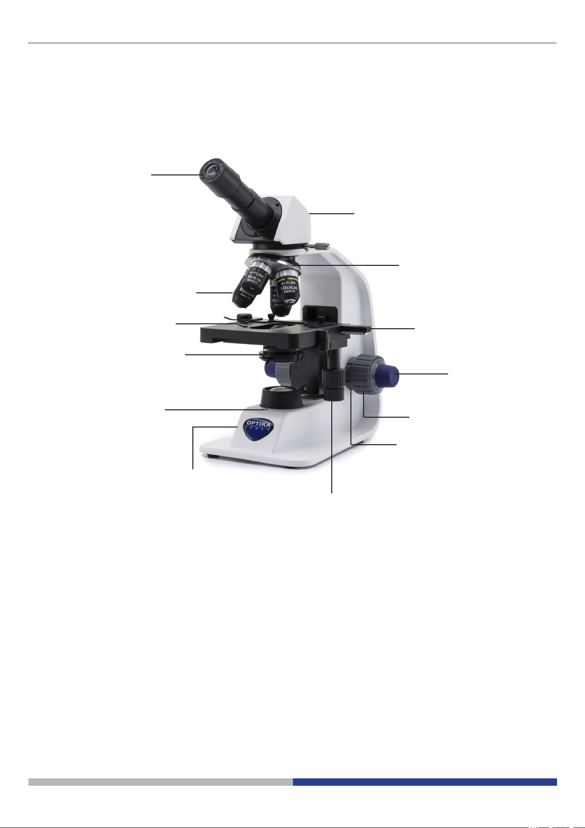
5.2 B-153 - B-155 - B-157 - B-159 /B-152R-PL -B-153R-PL -B-155R-PL -B-157R-PL -B-159R-PL
EYEPIECE
OBSERVATION HEAD
-) MONOCULAR (B-152 / B-153 / B-155)
-) BINOCULAR (B-157 / B-159)
NOSEPIECE
OBJECTIVES
SLIDE
HOLDER
CONDENSER
STAGE
FINE FOCUS
KNOB
LED CHARGE
INDICATOR
(ONLY “R”
VERSION)
MAIN SWITCH / INTENSITY
ADJUSTMENT DIAL
COARSE
FOCUS KNOB
TENSION
ADJUSTMENT
COLLAR
X/Y MOVEMENT
KNOBS
Page 5
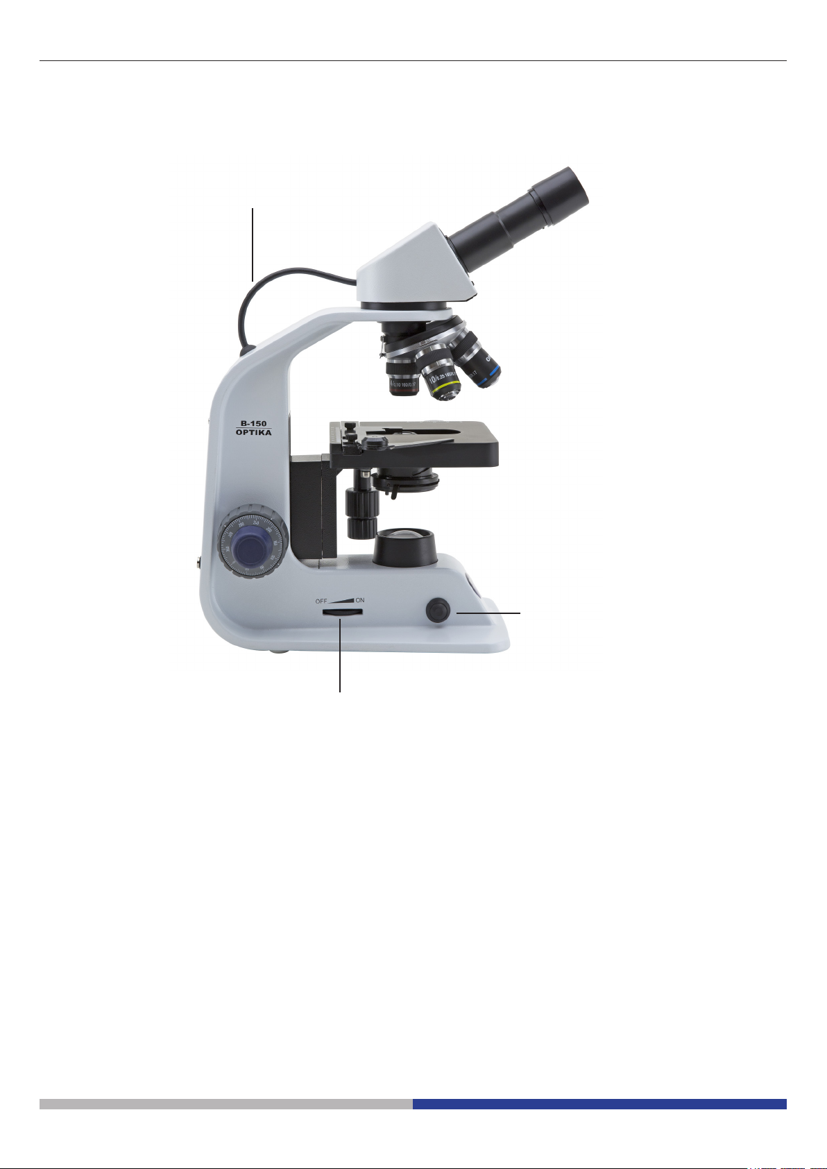
5.3 B-151ALC - B-153ALC - B-155ALC - B-157ALC - B-159ALC
ALC CONNECTION CABLE
MAIN SWITCH / INTENSITY
ADJUSTMENT DIAL
ALC ON/OFF BUTTON
Page 6
6. Unpacking
The microscope is housed in a moulded Styrofoam container. Remove the tape from the edge of the container
and lift the top half of the container. Take some care to avoid that the optical items (objectives and eyepieces)
fall out and get damaged. Using both hands (one around the arm and one around the base), lift the microscope
from the container and put it on a stable desk.
Do not touch with bare hands optical surfaces such as lenses, lters or glasses. Traces of grease or
other residuals may deteriorate the nal image quality and corrode the optics surface in a short time.
7. Assembling
Once opened the box, the microscope parts are the following:
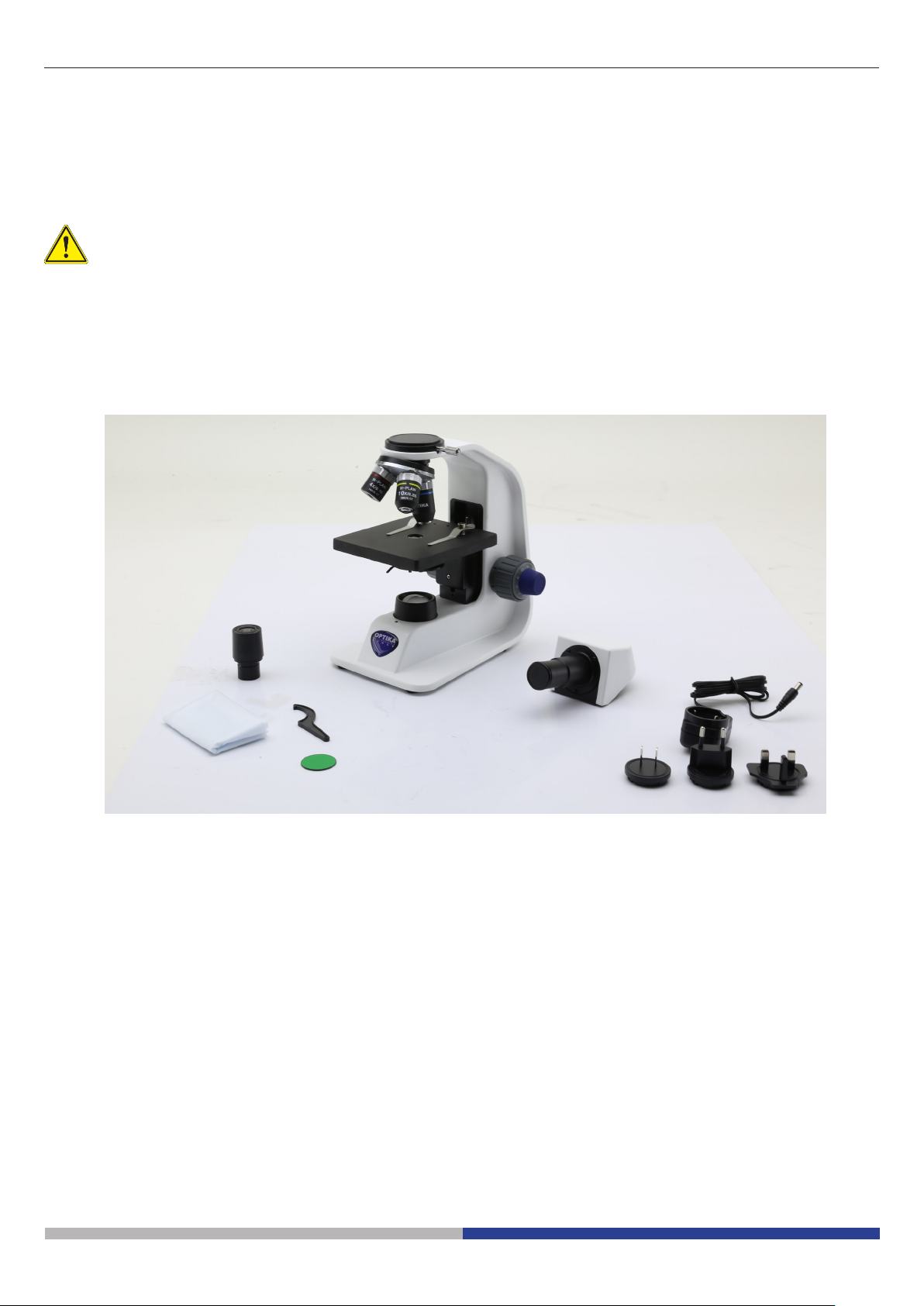
7.1 B-151 / B-151ALC / B-151R-PL
③
⑥
① Frame
② Monocular observation head
③ Eyepiece
④ Tension adjustment tool
⑤
⑦
①
②
④
⑧
⑤ Objectives (4X / 10X / 40X)
⑥ Dust cover
⑦ Green lter
⑧ Power supply
Page 7

7.2 B-152R-PL / B-153 / B-153ALC / B-153R-PL
③
⑥
① Frame
② Monocular observation head
③ Eyepiece
④ Tension adjustment tool
④
⑤
⑦
①
②
⑧
⑤ Objectives
B-152R-PL (4X / 10X / 40X)
B-153 (all) (4X / 10X / 40X / 60X)
⑥ Dust cover
⑦ Green lter
⑧ Power supply
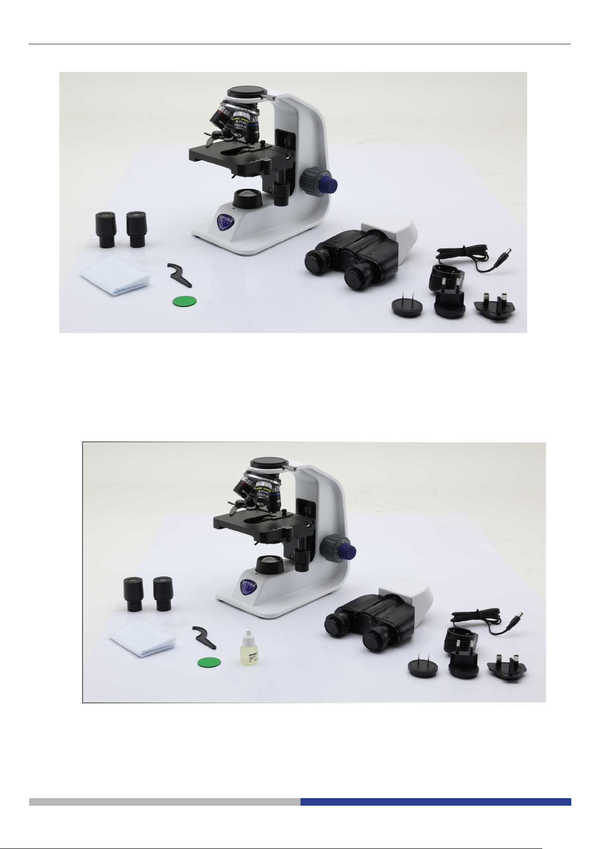
7.3 B-155 / B-155ALC / B-155R-PL
③
⑥
⑦ ⑧
① Frame
② Monocular observation head
③ Eyepiece
④ Tension adjustment tool
⑤ Objectives (4X / 10X / 40X / 100X)
⑤
④
①
②
⑨
⑥ Dust cover
⑦ Green lter
⑧ Power supply
⑨ Immersion oil
Page 8
7.4 B-157 / B-157ALC / B-157R-PL
③
⑥
① Frame
② Binocular observation head
③ Eyepiece
④ Tension adjustment tool
⑤
④
①
②
⑦
⑧
⑤ Objectives (4X / 10X / 40X / 60X)
⑥ Dust cover
⑦ Green lter
⑧ Power supply
7.5 B-159 / B-159ALC / B-159R-PL
⑤
③
④
⑥
⑦
①
②
⑨
⑧
① Frame
② Binocular observation head
③ Eyepiece
④ Tension adjustment tool
⑤ Objectives (4X / 10X / 40X / 100X)
⑥ Dust cover
⑦ Green lter
⑧ Power supply
⑨ Immersion oil
Page 9
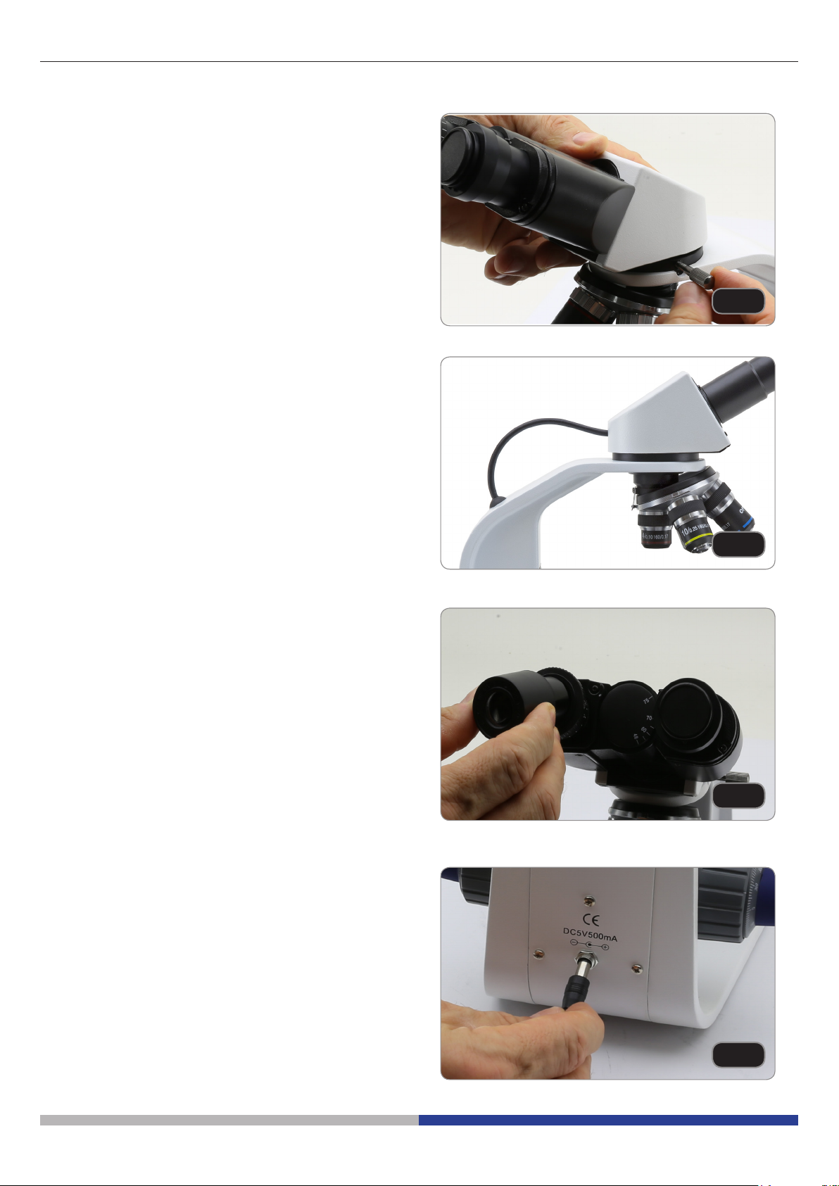
7.6 Assembling the microscope
1. Remove the dust cap from the microscope frame
and from the bottom of the observation head.
2. Insert the optical head above the stand and
tighten the screw. (Fig. 1)
• Hold the head with one hand during the locking in order to avoid that the head falls.
Only for ALC models:
3. Connect the cable of the ALC (Automatic Light Control) system to the socket placed on the observation head and on the back side of the frame. (Fig. 2)
Fig. 1
Fig. 2
4. Insert both eyepieces into the tubes of the optical
head. (Fig. 3)
• For models B-151, B-152, B-153 and B-155:
only one eyepiece is used as these models
are monocular.
5. Insert the power supply jack in the socket placed
at the rear side of the microscope. (Fig. 4)
Fig. 3
Page 10
Fig. 4
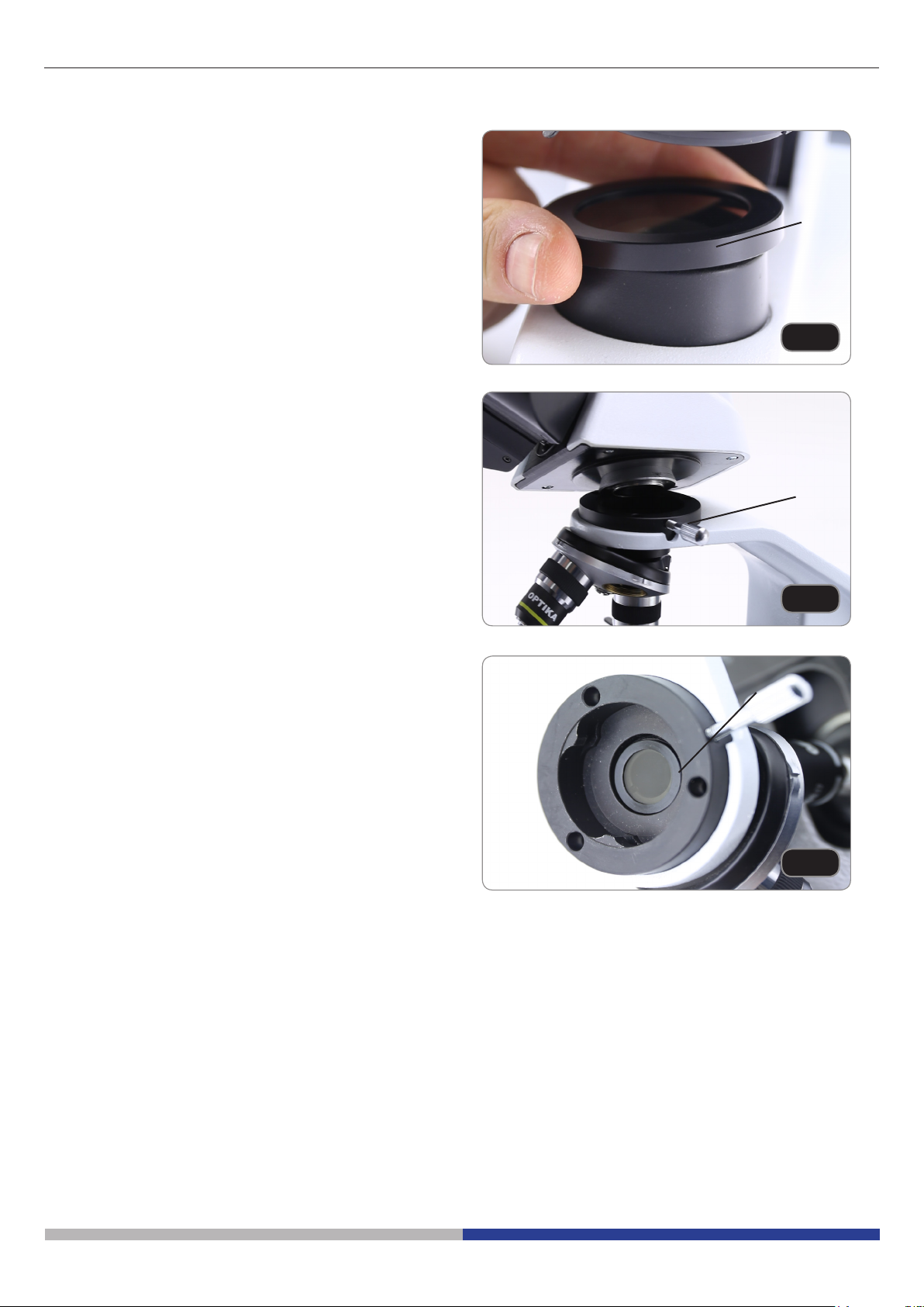
7.7 Polarizing set (optional)
1. Place the polarizer on the light exit ① at the base
of the microscope. (Fig. 5)
2. Loosen the head xing knob ② and remove the
head from the microscope frame. (Fig. 6)
①
Fig. 5
②
3. Insert the analyzer into the hole inside the frame
③. (Fig. 7)
4. Put back the head into its original position and
lock the xing knob.
Fig. 6
③
Fig. 7
Page 11
8. Use of the microscope
8.1 Light intensity adjustment
Operate on the light intensity adjustment dial to turn
ON / OFF the microscope and to increase / decrease
the illumination voltage ①. (Fig. 8)
8.2 Use of ALC system
1. Adjust the desired brightness through the eyepieces using the light intensity dial (chapter 8.1).
2. Press the ALC button ② to store this setting (Fig.
9). The light on the microscope will turn o for
some seconds, the will turn on again.
• The settings could not be working when the
light intensity is too low or too high. This is
not a defect.
3. Now the system will automatically adapt the
brightness to the eyepieces when an objective is
changed, when the aperture diaphragm is used
or when another specimen is placed on the stage.
4. Pressing the ALC button again, the ALC system
will be disabled.
• When ALC system is active the light intensity
dial is not active.
①
Fig. 8
②
Fig. 9
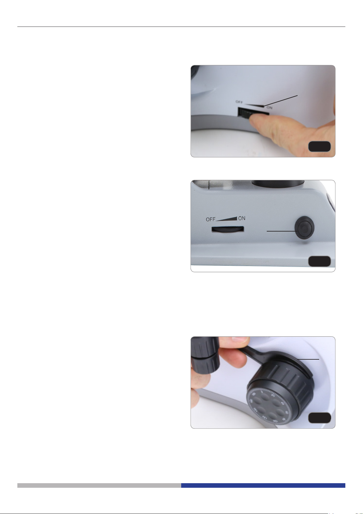
8.3 Coarse focus tension adjustment
• Adjust the tension using the provided tool.
The coarse knob tension is pre-setted in the factory.
To modify the tension according to personal’s needs,
rotate the ring ③ using the provided tool (Fig. 10).
Clockwise rotation increases the tension. If the tension is too loose, the stage could go lower by itself
or the focus easily lost after ne adjustment. In this
case, rotate the knob in order to increase the tension.
Page 12
③
Fig. 10
 Loading...