

Page 1

Version: 1
Issued: 25, 02, 2015
Model
B-1000POL
B-1000 Series
INSTRUCTION MANUAL
Page 2

Page 2
Table of Contents
Warning
Symbols and conventions
Safety Information
Intended use
List of accessories and spare parts
Overview
Unpacking
Assembling
Using the microscope
Maintenance
Troubleshooting
Equipment disposal
Page 3
Page 3
Warning
This microscope is a scientic precision instrument designed to last for many years with a minimum of maintenance. It is built to high optical and mechanical standards and to withstand daily use. We remind you that this
manual contains important information on safety and maintenance, and that it must therefore be made accessible to the instrument users. We decline any responsibility deriving from incorrect instrument use uses that does
not comply with this manual.
Symbols and conventions
The following chart is an illustrated glossary of the symbols that are used in this manual.
CAUTION
This symbol indicates a potential risk and alerts you to proceed with caution.
ELECTRICAL SHOCK
This symbol indicates a risk of electrical shock.
Safety Information
Avoiding Electrical Shock
Before plugging in the power supply, make sure that the supplying voltage of your region matches with the
operation voltage of the equipment and that the lamp switch is in off position. Users should observe all safety
regulations of the region. The equipment has acquired the CE safety label. However, users have full responsibility to use this equipment safely. Please follow the guidelines below, and read this manual in its entirety to ensure
safe operation of the unit.
Intended use
For research and teaching use only. Not intended for any animal or human therapeutic or diagnostic use.
Page 4

Page 4
List of accessories and spare parts
CAT. NO. DESCRIPTION
M-1001 WF10x/22mm eyepiece (pair)
M-1002 WF10x/24mm eyepiece (pair)
M-1004.N Centering telescope, 30mm diameter
M-781 WF10x/22mm micrometer eyepiece (10mm, 0.1mm div.)
M-1011 Trinocular Head (3 positions)
M-1012 Binocular ERGO head
M-1033 Bertrand Lens with Analyzer and slot for slides (with Lambda, 1/4 Lambda and Quartz Edge)
M-1044 Quintuple nosepiece with centrable positions for POL objectives
M-1080 4x IOS POL PLAN objective
M-1081 10x IOS POL PLAN objective
M-1082 40x IOS POL PLAN objective
M-1083 60x IOS POL PLAN objective
M-1145 Rotating Stage, centrable
M-1146 Attachable mechanical stage for rotating Stage
M-005 Micrometric slide, 26x76mm, range 1mm, div. 0,01mm
M-690 Eyecup (pair)
M-619 Photo tube adapter for full frame SLR camera
M-173 Photo tube adapter for APS-C SLR camera
M-699 Photo tube adapter for DIGI digital camera series
M-620 CCD camera adapter for 1/3’’ sensor
M-620.1 CCD camera adapter for ½’’ sensor
M-114 CCD camera adapter 0,45x
M-113.1 Ring adapter, 30mm (for monocular and binocular microscopes)
M-617.1N Phase contrast set with IOS PLAN objectives 40x
Page 5
Page 5
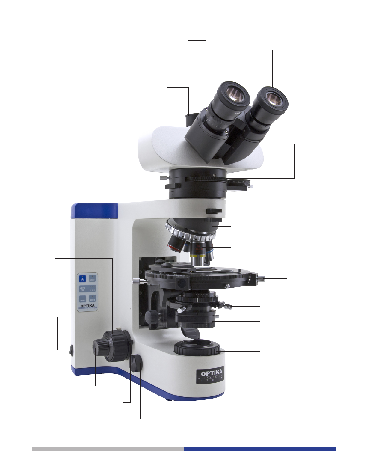
Overview
STAGE LOCK
KNOB
COARSE
FOCUSING
KNOB
NOSEPIECE
DIOPTRIC
ADJUSTMENT
RING
PHOTO PORT
MAIN ON/OFF
EYEPIECE
ANALYZER
FILTER
BERTRAND LENS
DISC
CONDENSER
CENTERING
KNOBS
APERTURE
DIAPHRAGM
POLARIZER
FIELD DIAPHRAGM
BRIGHTNESS
ADJUSTMENT KNOB
FOCUS-STOP KNOB
FINE FOCUSING
KNOB
OBJECTIVE
STAGE
FILTER
PLATE HOLDER
Page 6
Page 6
Put the microscope stand on a
solid table.
First insert the Bertrand lens
attachment, use the 2mm
Allen wrench to tighten the
screw.
All screws are already inserted into each threaded hole.
(Fig.1)
Unpacking
The microscope is housed in a moulded Styrofoam container. Remove the tape from the edge of the container
and lift the top half of the container. Take some care to avoid that the optical items (objectives and eyepieces)
fall out and get damaged. Using both hands (one around the arm and one around the base), lift the microscope
from the container and put it on a stable desk.
Assembling
Once you open the box, these are the microscope’s components:
① Condenser
② Optical head
③ Main body
④ Eyepieces
⑤ Power supply
⑥ Stage
⑦ Objectives
⑧ Bertrand lens and analyzer
⑨ Retardation plates
①
②
③
④
⑤
⑥
⑦
⑧ ⑨
Fig.1
Page 7

Page 7
Insert the condenser under
the stage: position until it is
well inserted into its holder
(under the condenser there is
a pin that must fully enter the
guide of the holder). (Fig. 4)
AFTER INSERTING THE
CONDENSER, TIGHTEN
THIS SCREW
Insert the optical head above
the Bertrand lens, using the
other 3mm Allen wrench to
tighten the screw. (Fig.2)
Insert both eyepieces into
the tubes of the optical head.
(Fig.3)
SPRING
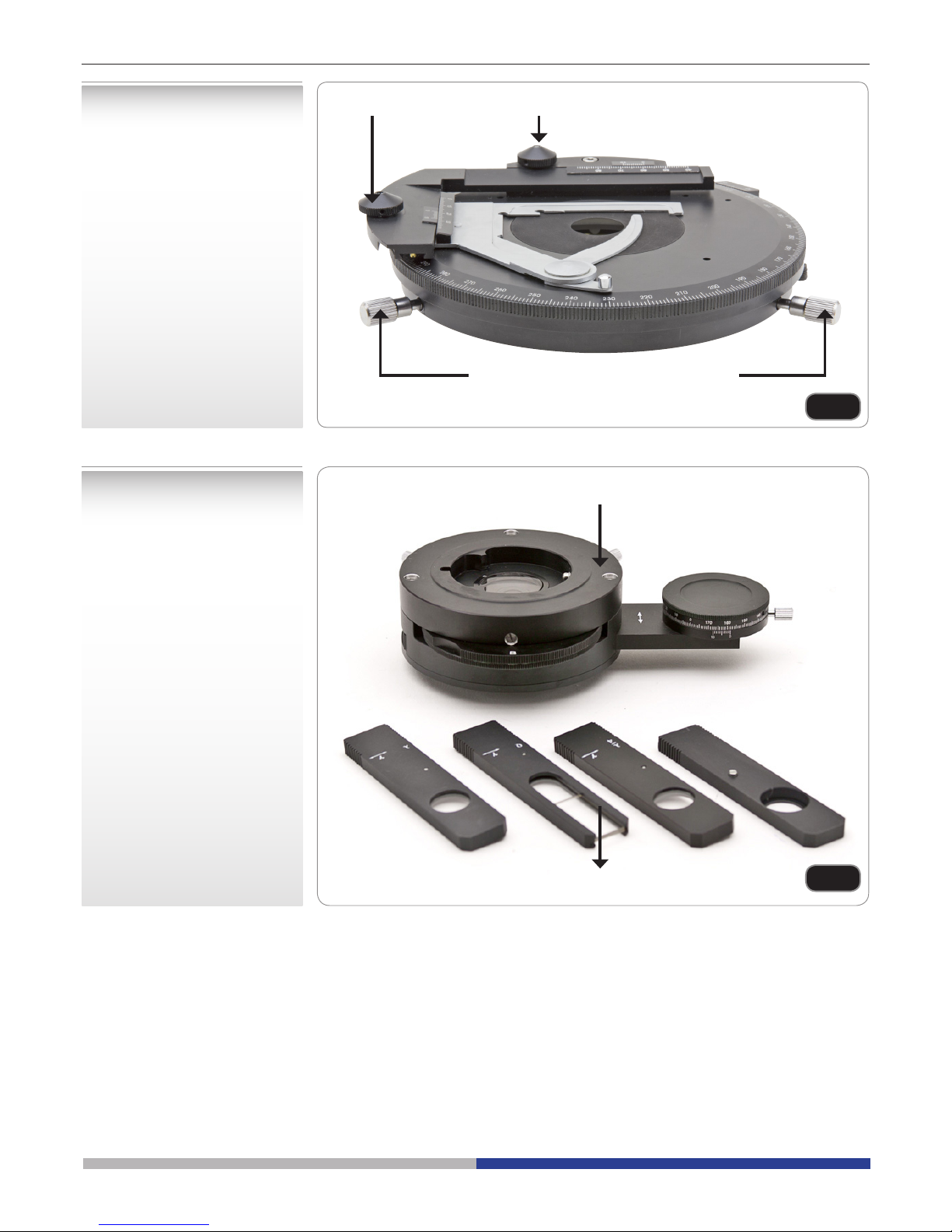
Mount the rotating stage: at
the bottom of the stage there
is a spring, push this spring
toward the stage support ①,
then push the stage
downward ②. (Fig.5)
Fig.2
Fig.3
Fig.4
Fig.5
①
②
Page 8
Page 8
Insert the retardation plates
by sliding them into the slot
under the optical head. (Fig.7)
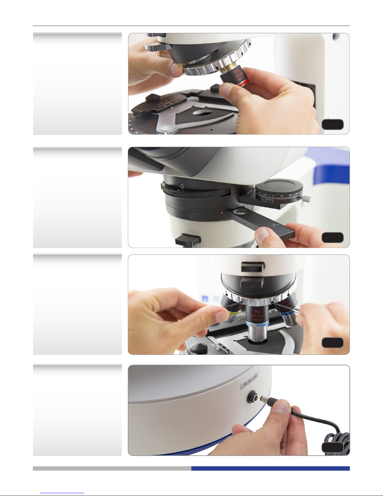
Center each objective using
the provided screwdrivers
(see chapter using the microscope). (Fig.8)
Insert the power supply jack
on the connector at the rear.
(Fig.9)
Screw each objective into the
thread of the nosepiece, in
order of magnication. (Fig.6)
Fig.6
Fig.7
Fig.8
Fig.9
Page 9

Page 9
The rotating stage is provided
with:
a) Stage centering knobs;
b) Stage lock knob;
c) 45° rotation clicks;
d) Optional X-Y translator.
(Fig.10)
The Bertrand lens attachment
is provided with
a) Analyzer lter;
b) Retardation plates;
c) Lens focus adjustment;
d) Lens X-Y centering screws.
(Fig.11)
X-Y TRANSLATION KNOBS
STAGE CENTERING KNOBS
BERTRAND LENS ATTACHMENT
RETARDATION PLATES
Fig.10
Fig.11
Page 10

Page 10
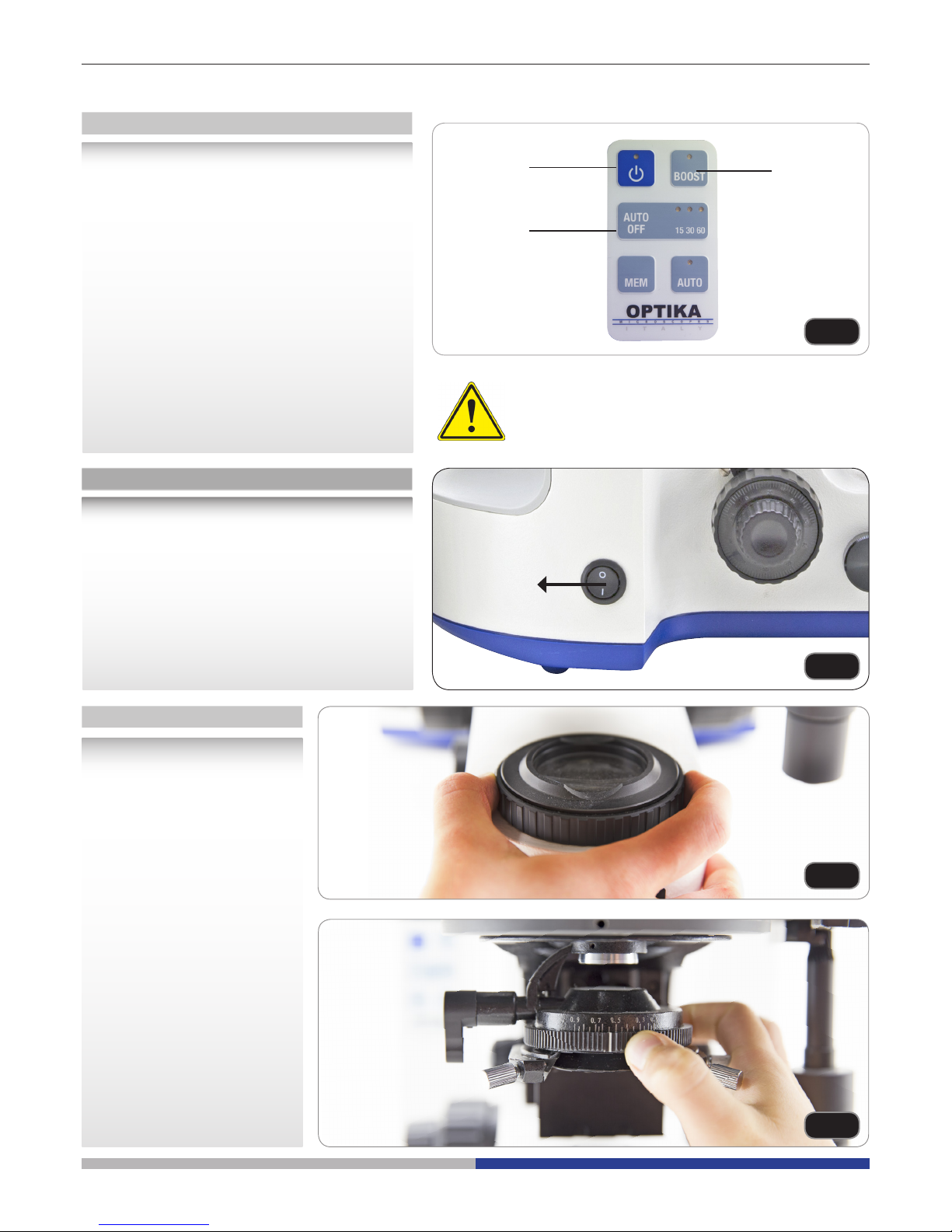
B-1000 illumination can be managed through
the keyboard placed on the left of the stand:
1) ON-OFF: press this button to turn on or off
the LED illuminator.
2) BOOST: press this button in order to incre-
ase the brightness (useful for high-magnication objectives or very opaque specimens).
2) AUTO-OFF: if you want the illuminator to
switch off automatically, press this button until
15, 30 or 60 minutes delay is set. After this
period of time, the light will turn off. You have
to press the ON-OFF button to turn it on again.
(Fig.12)
In order to activate the transmitted light illuminator, insert the plug of the external power
supply into the socket and turn on the main
switch on the side of the main body. Press
the ON-OFF button on the control keyboard
and turn the brightness adjustment knob to a
brightness suitable for observation. (Fig.13)
Do not enable boost mode while observing with
low magnication objectives (4x, 10x) with fully
open diaphgram: the high brightness may hurt
user’s eyes.
Control keyboard
LED settings
Preliminary settings
1) ON-OFF
3) AUTO-OFF
2) BOOST
MAIN
SWITCH
• The eld diaphragm is
fully open. (Fig.14)
• The aperture diaphragm
is fully open. (Fig.15)
• No lter is inserted under
the observation head.
Using the microscope
Fig.12
Fig.13
Fig.14
Fig.15
Before trying to focus the
sample, ensure that:
Page 11

Page 11
Loosen the lock-screw, turn
the observation head to
a comfortable position for
observation, and then lock the
lock-screw. (Fig.18)
Hold the right and left parts of
the observation head using
both hands and adjust the
interpupillary distance by
turning the two parts until one
circle of light can be seen.
(Fig.20)
Adjust the observation
head
Adjust interpupillary
distance
• The analyzer lter is in
OUT position (lever fully
pulled out). (Fig.16)
• Photo port closed
(lever on observation
head fully in).
• Bertrand lens in OUT position (you read “0” on the
Bertrand lens disc under
the observation head).
• (If you use 4X objective)
Swing out lens of the
condeser in OUT position.
(Fig.17)
Fig.16
Fig.17
Fig.18
Fig.20
Page 12
Page 12
Place the specimen on
the stage
Focus tension
adjustment
Focus-stop knob
Diopter adjustment
Fix the specimen slide on the
mechanical stage using the
slide-clamp. Ensure that the
specimen is centred over the
stage opening. (Fig.21)
Turn the tension-adjust knob
to get a suitable tension for
the focus system. (Fig.22)
NOTE: if the tension is too loose, the stage could go lower
by itself or the focus easily
lost after ne adjustment. In
this case, rotate the knob in
order to increase the friction.
Loosen the focus-stop knob,
rotate the coarse focusing
knob to bring the slide into
focus with a 4X or 10X objective. Then rotate the focus-stop
in order to block the height of
the stage. This simplies the
next focusing operations.
The focus-stop knob is also
useful to avoid accidental contacts between objective and
specimen. (Fig.23)
Adjust the ne focusing knob
to get the image sharp and
clear while observing with
your right eye, then turn the
left diopter ring to a sharp
and clear image also with the
other eye. The highpoint eyepieces allow the user to wear
glasses. (Fig.24)
NOTE :For the optimal parafocality of the image, it’s suggested to wear your glasses
during the normal use of the
microscope.
Fig.21
Fig.22
Fig.23
Fig.24
Page 13
Page 13
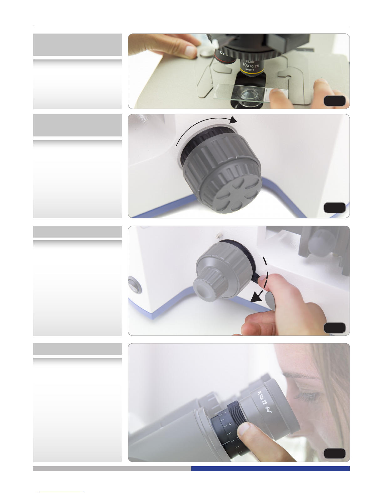
Centering the
condenser
Centering the stage
Insert the swing-out lens of
the condenser ① and fully close the eld diaphragm ②. Rotate the condenser adjustment
knob ③ until you see a sharp
image of the closed eld
diaphragm (a bright spot of
light). Act on the condenser
centering screws ④until you
move the bright spot in the
center of the image eld. Then
re-open the eld diaphragm
②. (Fig.25)
With the Bertrand lens out,
focus on your slide. In this
procedure we’ll center the
optical axis of each objective
with the rotation axis of the
stage. Insert the 10x objective, rotating the nosepiece.
Look at your sample while
continuously rotating the
stage clockwise and then
counter-clockwise by a little
angle (e.g. 30° or 45°). During
these oscillations you should
spot a point on the sample
that doesn’t rotate on a circumference but only revolving
about itself (it is the center of
the rotations). (Fig.27)
Adjust the aperture of the iris
diaphragm under the conden-
ser to set the numerical aperture of the illuminator, thus
controlling image contrast and
resolution. It is suggested to
set the aperture diaphragm
between 70% and 80% of
objective’s N.A. (Fig.26)
①
③
④
②
A= FIXED POINT
(Center of rotation)
B= ROTATING POINT
Center of rotation on the optical axis.
Fig.25
APERTURE IRIS
DIAPHRAGM IMAGE
CENTERING THE CONDENSER
OBJECTIVE PUPIL
30-20%
70-80%
Fig.26
Fig.27
Page 14
Page 14
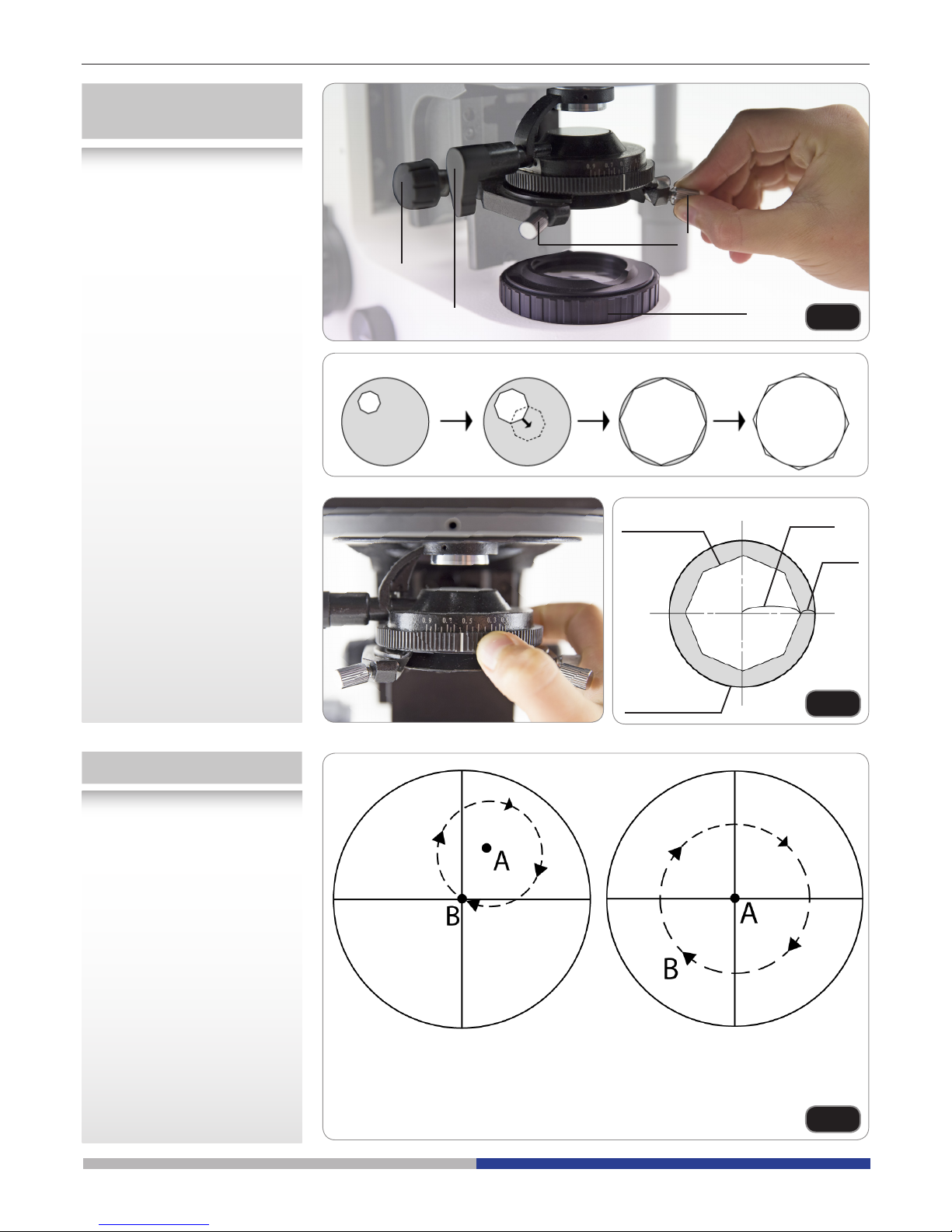
Using the stage centering
screws, bring this point in
the center of the eld of view.
In this way the mechanical
center of rotation of the stage
coincides with the system’s
optical axis. (Fig.28)
Insert another objective, rotating the nosepiece. Repeat
the above operation (stage
rotations), and bring the point
into the center using the
objective centering screws
(not the stage centering
screws). (Fig.29)
NOTE :The stage can be
locked in its position using the
stage lock knob.
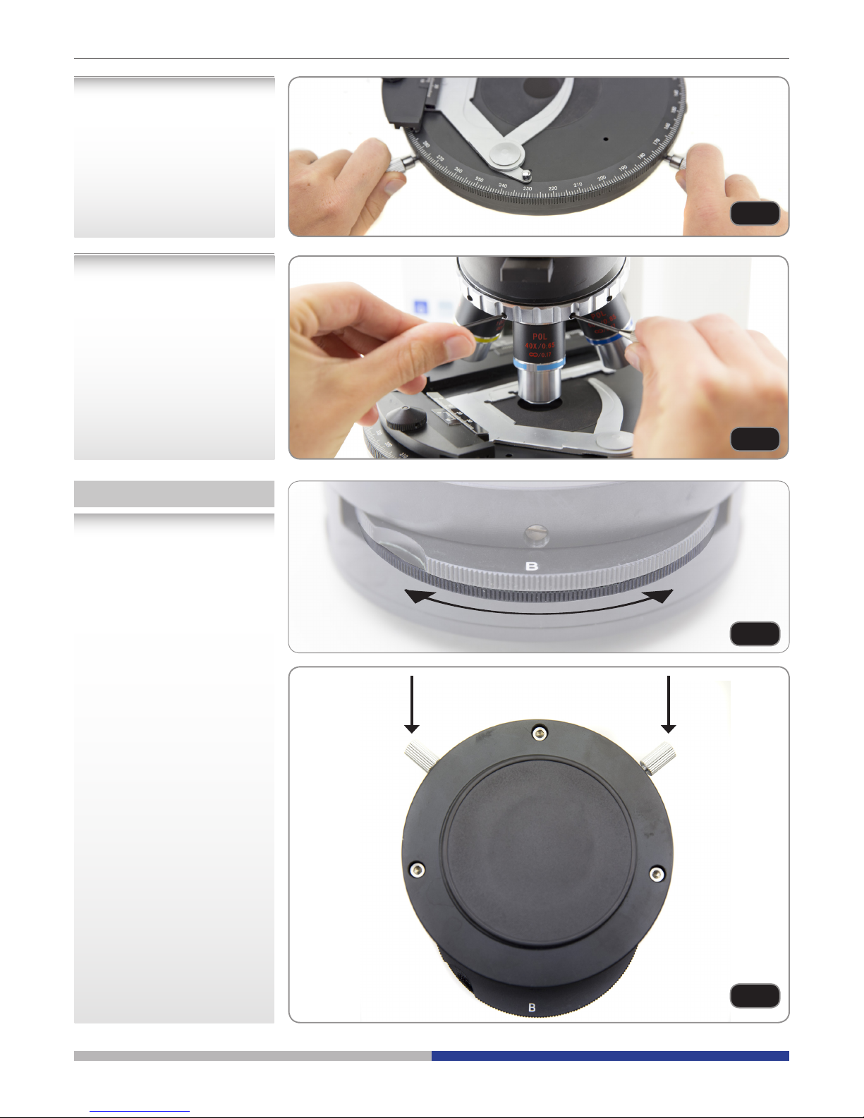
Bertrand lens
In order to have a conoscopic
view of your sample, you can
insert a Bertrand lens in the
optical path by rotating the
disc under the observation
head.
The Bertrand lens can be ne
aligned along Z axis by rotating this disc. (Fig.30)
The lens can also be centered
in X-Y axis by means of two
screws located at the back of
the lens. (Fig.31)
Fig.28
Fig.29
Fig.30
Fig.31
Page 15
Page 15
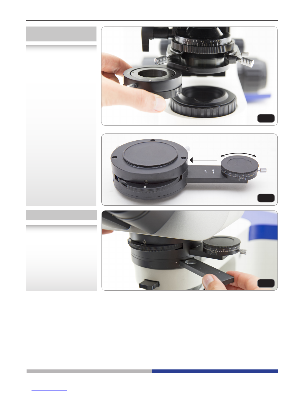
Polarizer and analyzer
lters
Retardation lter plates
Insert or remove the lower
polarizer as required. It can
also be rotated at any angle.
(Fig.32)
The microscope is provided
with these retardation plates:
lambda, lambda/4 and quartz
wedge. You can insert them
in the optical path, sliding the
plate holder in the slot under
the observation head.
(Fig.34)
The analyzer lter can be
inserted by pushing the slider
inward. By rotating the front
disc, it can also be rotated at
any angle. (Fig.33)
Fig.32
Fig.33
Fig.34
Page 16

Page 16
Maintenance
Microscopy environment
This microscope is recommended to be used in a clean, dry and shock free environment with a temperature of
5°-40°C and a maximum relative humidity of 75 % (non condensing). Use a dehumidier if needed.
To think about when and after using the microscope
• The microscope should always be kept vertically when moving it and be careful so that no
moving parts, such as the eyepieces, fall out.
• Never mishandle or impose unnecessary force on the microscope.
• Never attempt to service the microscope yourself.
• After use, turn off the light immediately, cover the microscope with the included
dust-cover, and keep it in a dry and clean place.
Electrical safety precautions
• Before plugging in the power supply, make sure that the supplying voltage of your region
matches with the operation voltage of the equipment and that the lamp switch is in off-
position.
•
Users should observe all safety regulations of the region. The equipment has acquired
the CE safety label. However, users do have full responsibility to use this equipment safely.
Cleaning the optics
• If the optical parts need to be cleaned try rst to: use compressed air.
• If that is not sufcient: use a soft lint-free piece of cloth with water and a mild detergent.
• And as a nal option: use the piece of cloth moistened with a 3:7 mixture of ethanol and ether.
Note: ethanol and ether are highly ammable liquids. Do not use them near a heat source, near sparks or
near electric equipment. Use these chemicals in a well ventilated room.
• Remember to never wipe the surface of any optical items with your hands. Fingerprints can damage the
optics.
• Do not disassemble objectives or eyepieces in attempt to clean them.
For the best results, use the OPTIKA cleaning kit (see catalogue).
If you need to send the microscope to Optika for maintenance, please use the original packaging.
Page 17

Page 17
Troubleshooting
Review the information in the table below to troubleshoot operating problems.
PROBLEM CAUSE SOLUTION
1. Optical System
LED does not light. Power cord is unplugged. Plug power cord into the power outlet.
LED operates, but eld of view
remains dark.
Aperture and eld iris diaphragms are
not opened wide enough.
Adjust them to proper sizes.
Condenser is lowered too much. Adjust the condenser height position.
Light path selector knob is set to the
camera position.
Move the knob to the eye position.
Field of view is obscured or
not evenly illuminated
Light path selector knob is in an inter-
mediate position.
Set the knob according to the observation
method.
Revolving nosepiece is not correctly
engaged.
Make sure that the revolving nosepiece
clicks properly into place.
Condenser is not attached properly. Re-attach it.
Revolving nosepiece is not attached
properly.
Push the side dovetail all the way until it is
stopped.
An objective that falls outside of the
condenser’s illumination range is used.
Use a condenser to match the purpose.
Condenser is not properly centered. Center the condenser.
Field iris diaphragm is stopped down
too far.
Open the field iris diaphragm until it circumscribes the field.
Dirt or dust is visible in the
field of view.
Dirt/dust on the eyepieces Clean thoroughly.
Dirt or the to surface of the condenser
Dirt/dust on the specimen
Visibility is poor.
· Image is not poor.
· Contrast is poor.
· Details are indistinct.
· Image glares.
Condenser is lowered too far. Adjust the condenser height position.
Aperture iris diaphragm is stopped
down too far.
Open aperture iris diaphragm.
Revolving nosepiece is not mounted
properly.
Push the slide dovetail all the way until
it is stopped.
Front lens of objective is dirty. Clean objective.
Immersion oil is not being used with an
oil immersion objective.
Use immersion oil.
Immersion oil contains bubbles. Remove the bubbles.
Recommended immersion oil is not
used.
Use the provided immersion oil.
Dirt/dust on specimen. Clean it.
Dirt/dust on condenser
Inappropriate object side or cover
glass thickness.
Replace with glass of recommended thick-
ness.
Page 18

Page 18
PROBLEM CAUSE SOLUTION
One side of image is blurred. Objective is not correctly engaged in light
path.
Make sure that revolving nosepiece
clicks into place correctly.
Revolving nosepiece is not correctly
mounted.
Push slide dovetail all the way until it
is stopped.
Stage is not correctly mounted. Re-attach it.
Specimen is not correctly mounted on
stage.
Place specimen correctly on to of
stage and secure it with slide holder.
Image appears to waver. Revolving nosepiece is not corrected
mounted.
Push slide dovetail all the way until it
is stopped.
Objective is not correctly engaged in light
path.
Make sure that revolving nosepiece
clicks into place correctly.
Condenser is not properly centered. Center the condenser.
Field of view becomes only
slightly brighter when the vol-
tage is raised.
Condenser is not properly centered. Center the condenser.
Condenser is lowered too far. Adjust the condenser height position.
2. Coarse/Fine
Adjustment
Coarse adjustment knob is
hard to turn.
Tension adjustment ring is tightened
excessively.
Loose ring.
You are trying to raise stage while focuslock lever is kept locked.
Unlock focus-look lever
Stage drifts down by itself or
focus is lost during observa-
tion.
Tension adjustment ring is too loose. Tighten ring.
Coarse adjustment will not go
all the way up.
Focus-look lever is locked at a too low
height.
Unlock focus-look lever.
Coarse adjustment will not go
all the way down.
Condenser holder is too low. Raise condenser holder.
Objective makes contact with
specimen before focus is
obtained.
Specimen is mounted upside down. Mount specimen correctly.
3. Observation Tube
Field of view of one eye does
not match that of the other.
Interpupillary distance is incorrect. Adjust interpupillary distance.
Incorrect diopter adjustment. Adjust diopter.
Different eyepieces are used on left and
right.
Change on eyepiece to match the other so
that both sides are the same type.
Your view is not accustomed to microscope observation.
Upon looking into eyepieces, try looking at
overall field before concentrating
on specimen range. You may also
find it helpful to look up and into distance
for a moment before looking back into
microscope.
4. Stage
Image shifts when you touch
stage.
Stage is not properly mounted. Clamp stage.
Specimen stops midway on
the Xaxis traverse.
Specimen is not correctly positioned. Place specimen correctly.
X- and Y-axis knobs are too
tight or too loose.
Tension of X- and Y-axis knobs is too high
or too low.
Adjust tension.
Page 19
Page 19
Equipment disposal
Art.13 Dlsg 25 july 2005 N°151. “According to directives 2002/95/EC, 2002/96/EC and 2003/108/EC relating
to the reduction in the use of hazardous substances in electrical and electronic equipment and waste disposal.”
The basket symbol on equipment or on its box indicates that the product at the end of its useful life should be
collected separately from other waste.
The separate collection of this equipment at the end of its lifetime is organized and managed by the producer.
The user will have to contact the manufacturer and follow the rules that he adopted for end-of-life equipment
collection.
The collection of the equipment for recycling, treatment and environmentally compatible disposal, helps to prevent
possible adverse effects on the environment and health and promotes reuse and/or recycling of materials of the
equipment.
Improper disposal of the product involves the application of administrative penalties as provided by the laws in force.
Page 20

Page 21

Versione: 1
Emesso il: 25, 02, 2015
Modello
B-1000POL
Serie B-1000
MANUALE D’ISTRUZIONI
Page 22

Pagina 22
Sommario
Avvertenze
Simboli e convenzioni
Informazioni di sicurezza
Applicazioni d’uso
Lista accessori e ricambi
Panoramica
Disimballaggio
Assemblaggio
Uso del microscopio
Manutenzione
Risoluzione problemi
Misure ecologiche
Page 23

Pagina 23
Avvertenze
Il presente microscopio è uno strumento scientico di precisione studiato per durare molti anni con una manutenzione minima, essendo costruito secondo i migliori standard ottici e meccanici e progettato per un
utilizzo quotidiano. Vi ricordiamo che il presente manuale contiene informazioni importanti sulla sicurezza e
manutenzione dello strumento, e deve quindi essere accessibile a chiunque lo utilizzi. Optika declina ogni
responsabilità derivante da un uso improprio dei suoi strumenti non indicato nella presente guida.
Simboli e convenzioni
Il seguente paragrafo è un glossario illustrato dei simboli usati nel manuale.
ATTENZIONE
Questo simbolo indica un potenziale rischio e vi avvisa di procedere con attenzione.
SHOCK ELETTRICO
Questo simbolo indica un rischio di shock elettrico.
Informazioni sulla Sicurezza
Precauzioni sicurezza elettrica
Prima di collegare il cavo di alimentazione alla presa di rete, assicurarsi che il voltaggio della rete elettrica del
vostro Paese sia compatibile con il voltaggio di alimentazione dello strumento, e che l’interruttore dell’illuminatore
sia sulla posizione spenta. L’utente deve osservare la regolamentazione riguardante la sicurezza in vigore nel
proprio Stato. Lo strumento è dotato di marcatura di sicurezza CE. In ogni caso, l’utente ha piena responsabilità
riguarda l’utilizzo sicuro dello strumento stesso. Prego fare attenzione alle seguenti linee guida, leggere il manuale per intero al ne di operare in sicurezza.
Applicazioni d’uso
Solo per applicazioni di ricerca ed usi didattici. Non indicato per utilizzo diagnostico e terapeutico
umano e veterinario.
Page 24

Pagina 24
Lista accessori e ricambi
COD. DESCRIZIONE
M-1001 Oculari WF10x/22mm (coppia)
M-1002 Oculari WF10x/24mm (coppia)
M-1004.N Telescopio di centratura per contrasto di fase, 30mm di diametro
M-781 Oculare micrometrico WF10x/22mm (10mm, div.0,1mm)
M-1011 Testata trinoculare (3 posizioni)
M-1012 Testata binoculare ERGO
M-1033 Lente di Bertrand con Analizzatore e slitta per lamine (con Lambda, ¼ Lambda e cuneo di
quarzo)
M-1044 Revolver quintuplo con sistema di centratura per obiettivi POL
M-1080 Obiettivo PLAN IOS POL 4x
M-1081 Obiettivo PLAN IOS POL 10x
M-1082 Obiettivo PLAN IOS POL 40x
M-1083 Obiettivo PLAN IOS POL 60x
M-1145 Tavolino ruotante, centrabile
M-1146 Meccanismo traslatore per tavolino ruotante
M-005 Vetrino micrometrico, 26x76mm, range 1mm, div. 0,01mm
M-690 Paraocchi (coppia)
M-619 Adattatore fotografico per Reflex con sensore Full Frame
M-173 Adattatore fotografico per Reflex con sensore APS-C
M-699 Adattatore fotografico per fotocamera digitale DIGI
M-620 Adattatore per telecamere CCD con sensore 1/3”
M-620.1 Adattatore per telecamere CCD con sensore 1/2”
M-114 Adattatore per telecamera CCD 0,45x
M-113.1 Anello adattatore, 30mm (per microscopio monoculare e binoculare)
M-617.1N Set per contrasto di fase, Obiettivo PLAN IOS 40x
Page 25

Pagina 25
Panoramica
MANOPOLA DI
BLOCCO TAVOLINO
MANOPOLA DI
MESSA A FUOCO
MACROMETRICA
REVOLVER
ANELLO
REGOLAZIONE
DIOTTRICA
USCITA FOTO/VIDEO
PULSANTE
ON/OFF
OCULARE
FILTRO
ANALIZZATORE
LENTE DI
BERTRAND
MANOPOLE
CENTRAGGIO
CONDENSATORE
DIAFRAMMA DI
APERTURA
POLARIZZATORE
DIAFRAMMA DI
CAMPO
MANOPOLA REGOLAZIONE
LUMINOSITA’
MANOPOLA BLOCCO
MESSA A FUOCO
MANOPOLA MESSA A
FUOCO MICROMETRICA
OBIETTIVO
TAVOLINO
ALLOGGIAMENTO
LAMINE DI RITARDO
Page 26

Pagina 26
Posizionare lo stativo del
microscopio su un piano
stabile.
Per iniziare, inserire il dispositivo con la Lente di Bertrand,
utilizzando la chiave a brugola
2mm per stringere le viti.
Tutte le viti sono già posizionate ognuna nel relativo foro
lettato. (Fig.1)
Disimballaggio
Il microscopio è riposto in un imballo di polistirolo espanso. Rimuovere il nastro adesivo dal collo ed aprire la
parte superiore dell’imballo. Fare attenzione a non far cadere le parti ottiche (obiettivi e oculari) nell’estrarre il
microscopio dalla scatola per evitare che vengano danneggiati. Utilizzare entrambe le mani (una intorno allo
stativo e una alla base), slare il microscopio dal contenitore e appoggiarlo su un piano stabile.
Assemblaggio
All’apertura della scatola, i componenti del microscopio sono i seguenti:
①
②
③
④
⑤
⑥
⑦
⑧ ⑨
Fig.1
① Condensatore
② Testata ottica
③ Stativo
④ Oculari
⑤ Alimentatore
⑥ Tavolino
⑦ Obiettivi
⑧ Lente di Bertrand e
Analizzatore
⑨ Lamine di ritardo
Page 27

Pagina 27
Inserire il condensatore sotto
il tavolino: controllare che
sia correttamente inserito
nel suo alloggiamento (sotto
il condensatore si trova uno
spinotto che deve entrare
completamente nella guida
dell’alloggiamento). (Fig. 4)
DOPO AVER INSERITO IL
CONDENSATORE,
STRINGERE QUESTA VITE
Inserire la testata ottica al di
sopra della lente di Bertrand,
usando la chiave a brugola
da 3mm per stringere le viti.
(Fig.2)
Inserire entrambi gli oculari
nei tubi portaoculari della
testata ottica. (Fig.3)
MOLLA
Montare il tavolino ruotante:
sotto il tavolino è posizionata
una molla, spingere questa
molla verso il supporto del
tavolino ①, poi spingere il
tavolino verso il basso ②.
(Fig.5)
Fig.2
Fig.3
Fig.4
Fig.5
①
②
Page 28

Pagina 28
Inserire le lamine di ritardo
facendole scorrere all’interno
della slitta sotto la testata
ottica. (Fig.7)
Centrare ciascun obiettivo
usando i cacciaviti in dotazione (vedi paragrafo utilizzo
microscopio). (Fig.8)
Inserite la spina del cavo di
alimentazione alla presa sul
retro dello stativo. (Fig.9)
Avvitare ciascun obiettivo nel
foro lettato del revolver, in ordine di ingrandimento. (Fig.6)
Fig.6
Fig.7
Fig.8
Fig.9
Page 29
Pagina 29
Il tavolino ruotante è dotato di:
a) Viti di centraggio tavolino;
b) Vite di ssaggio tavolino;
c) clickstop di rotazione di 45°;
d) movimento traslatore X-Y
opzionale. (Fig.10)
Il dispositivo con Lente di
Bertrand è dotato:
a) Filtro analizzatore;
b) Lamine di ritardo;
c) regolazione messa a fuoco
lenti;
d) Viti di centraggio lenti X-Y.
(Fig.11)
MANOPOLE DI TRASLAZIONE X-Y
VITI DI CENTRAGGIO TAVOLINO
DISPOSITIVO LENTE DI BERTRAND
LAMINE DI RITARDO
Fig.10
Fig.11
Page 30
Pagina 30
L’illuminazione del B-1000 può essere controllata tramite tastiera posizionata sul lato
sinistro dello stativo:
1) ON-OFF: premere questo pulsante per
accendere/spegnere l’illuminatore LED.
2) BOOST: premere questo pulsante per
incrementare la luminosità (utile per obiettivi
ad elevati ingrandimenti e preparati molto
opachi).
2) AUTO-OFF: se desiderate che l’illuminatore
si spenga automaticamente, premete questo
pulsante no a impostare il tempo necessario
15, 30 o 60 minuti. Alla ne di questo periodo
di tempo, la luce si spegnerà. Dovrete premere il pulsante ON-OFF per accenderla nuovamente. (Fig.12)
Per attivare l’illuminatore in luce trasmessa,
inserire la spina dell’alimentatore esterno nella
presa di rete ed accendere l’interruttore principale sul lato dello stativo. Premere il pulsante
ON-OFF sulla tastiera laterale e ruotare la
manopola di regolazione della luminosità no
ad ottenere la luminosità adeguata all’osservazione. (Fig.13)
Non è possibile osservare in modalità BOOST
con obiettivi a bassi ingrandimenti (4x, 10x) e
con il diaframma di apertura completamente
aperto: l’elevata luminosità può danneggiare gli
occhi.
Tastiera di controllo
Regolazione LED
Impostazioni preliminari
1) ON-OFF
3) AUTO-OFF
2) BOOST
INTERRUTTORE
PRINCIPALE
• Il diaframma di campo sia
completamente aperto.
(Fig.14)
• Il diaframma di apertura
sia completamente aperto. (Fig.15)
• Nessun ltro deve essere
inserito sotto la testata di
osservazione.
Utilizzo del microscopio
Fig.12
Fig.13
Fig.14
Fig.15
Prima di tentare la messa a
fuoco del campione, assicu-
rarsi che:
Page 31

Pagina 31
Allentare le viti di ssaggio,
ruotate la testata in posizione
confortevole per l’osservazione, poi stringere le viti di
ssaggio.(Fig.18)
Tenere la parte destra e sinistra della testata d’osservazione usando entrambe le mani e
regolare la distanza interpupillare ruotando le due parti no
ad ottenere la visione di un
unico cerchio di luce. (Fig.20)
Regolazione della
testata d’osservazione
Regolazione distanza
interpupillare
• Il ltro analizzatore sia in
posizione OUT (leva tirata
interamente verso l’esterno). (Fig.16)
• Uscita foto/video chiusa
(leva nella testata d’osservazione inserita completamente).
• Lente di Bertrand in
posizione OUT (leggete
“0” sul disco della lente di
bertrand sotto la testata
d’osservazione).
• (Se usate l’obiettivo 4X)
Slittate la lente del condensatore in posizione
OUT. (Fig.17)
Fig.16
Fig.17
Fig.18
Fig.20
Page 32

Pagina 32
Posizionamento del
preparato sul tavolino
Regolazione tensione
di messa a fuoco
Manopola di blocco
messa a fuoco
Regolazione diottrica
Fissare il vetrino preparato sul
tavolino traslatore utilizzando
le pinzette.
Assicurarsi che il preparato
sia centrato sull’apertura del
tavolino. (Fig.21)
Ruotare la manopola di regolazione della tensione no ad
ottenere un’adeguata tensione
del sistema di messa a fuoco.
(Fig.22) NO TA : se la tensione è troppo bassa, il tavolino
tende a scendere da solo
verso il basso o la messa a
fuoco viene persa facilmente
dopo la regolazione micrometrica. In questo caso, ruotate
la manopola per aumentare la
tensione.
Allentare la manopola di
blocco della messa a fuoco,
ruotare la manopola di regolazione macrometrica no a
mettere a fuoco il vetrino con
obiettivo 4x o 10x. Poi ruotare
il blocco del focus per ssare
l’altezza del tavolino. Questo
semplicherà le operazioni di
messa a fuoco successive.La
manopola di blocco della messa a fuoco è utile anche per
evitare l’accidentale contatto
tra obiettivi e preparato.
Regolare la micrometrica no
a ottenere un’immagine chiara
e nitida osservando col vostro
occhio destro, poi ruotare
l’anello di regolazione diottrica
sull’oculare sinistro no ad
ottenere la visione chiara e
nitida anche con l’alto occhio.
Gli oculari highpoint permette
l’uso anche da parte dei portatori di occhiali. (Fig.24)
NO TA :Per una parafocalità
ottimale, si consiglia di utilizzare i vostri occhiali durente
il normale utilizzo del micro-
scopio.
Fig.21
Fig.22
Fig.23
Fig.24
Page 33

Pagina 33
Centraggio del
condensatore
Centraggio del tavolino
Inserire la lente swing-out del
condensatore ① e chiudere
completamente il diaframma di campo ②. Ruotare
la manopola di regolazione
del condensatore ③ no ad
ottenere un’immagine chiara e
nitida del diaframma di campo
chiuso (un chiaro punto di
luce). Agira sulle viti di centraggio del condensatore
④ nchè quel punto di luce
si trovi al centro del campo
visivo. Riaprire il diaframma di
campo ②. (Fig.25)
Con la lente di Bertrand
disinserita, mettere a fuoco il
campione. In questa procedura dovremo centrare gli assi
ottici di ciascun obiettivo con
l’asse di rotazione del tavolino. Inserire l’obiettivo 10x,
ruotando il revolver. Osservare il campione ruotando il tavolino in senso orario e poi in
senso antiorario di pochi gradi
(30° o 45°). Durante questa
rotazione potrete notare un
punto del campione che non
ruota su una circonferenza ma
che ruota su sé stesso. (esso
è il centro della rotazione).
(Fig.27)
Regolare l’apertura del
diaframma ad iride sotto il
condensatore per impostare
l’apertura numerica dell’illuminatore, al ne di regolare
il contrasto e la risoluzione
dell’immagine. Si consiglia di
impostare l’apertura numerica
tra il 70% e l’80% dell’apertura numerica dell’obiettivo.
(Fig.26)
①
③
④
②
A= PUNTO FISSO
(Centro di rotazione)
B= PUNTO RUOTANTE
Centro di rotazione sugli assi ottici.
Fig.25
VISIONE DEL DIAFRAMMA
AD IRIDE
CENTRARE IL CONDENSATORE
CAMPO VISIVO
30-20%
70-80%
Fig.26
Fig.27
Page 34

Pagina 34
Usando le viti di centraggio
del tavolino, porre questo punto al centro del campo visivo.
Così il centro meccanico di
rotazione del tavolino coincide
con gli assi del sistema ottico.
(Fig.28)
Inserire un altro obiettivo, ruotando il revolver. Ripetere le
operazioni come sopra (rotazione tavolino), e porre il punto sso al centro usando le viti
di centraggio dell’obiettivo(non
le viti di centraggio del tavolino). (Fig.29)
NO TA : Il tavolino può essere
bloccato nella sua posizione
mediante la manopola di blocco tavolino.
Lente di Bertrand
Per ottenere una visione
conoscopica del campione,
potete inserire la Lente di
Bertrand nel percorso ottico
ruotando il disco posto sotto la
testata.
La Lente di Bertrand può
essere allineata sull’asse Z
ruotando il suo disco. (Fig.30)
La lente può anche essere
centrata sugli assi X-Y tramite
le due viti posizionate sul retro
della lente. (Fig.31)
Fig.28
Fig.29
Fig.30
Fig.31
Page 35

Pagina 35
Filtri polarizzatore e
analizzatore
Lamine di ritardo
Inserire o rimuovere il polarizzatore inferiore come richiesto. Esso può essere ruotato
in ogni angolazione. (Fig.32)
Il microscopio è dotato delle
seguenti lamine di ritardo:
lambda, lambda/4 e cuneo
di quarzo. Voi potete inserirli
nel percorso ottico, o scorrere
le varie posizioni della slitta
sottostante la testata d’osservazione.
(Fig.34)
Il ltro analizzatore può essere inserito premendo la slitta
verso l’interno. Mentre ruotando il disco frontale può essere
ruotato in goni angolazione.
(Fig.33)
Fig.32
Fig.33
Fig.34
Page 36

Pagina 36
Manutenzione
Condizioni ambientali
Si raccomanda di utilizzare il microscopio in un ambiente pulito, asciutto e privo di shock elettrici e con una
temperatura ambiente tra 5°-40°C ed una umidità relativa massima di 75 % (in assenza di condensa). Utilizzare
deumidicatore ove necessario.
Da ricordare durante e dopo l’utilizzo del microscopio
• Il microscopio deve sempre essere tenuto in posizione verticale durante gli spostamenti e
porre attenzione che i componenti mobili, come gli oculari, non cadano.
• Maneggiare con cura e non adoperare inutile fora sul microscopio.
• Non provvedere alla manutenzione da soli.
• Dopo l’uso, spegnere immediatamente la luce, coprire il microscopio con la copertina antipolvere in dotazione, e riporre in luogo asciutto e pulito.
Precauzioni per la sicurezza elettrica
• Prima di collegare l’alimentatore, assicurarsi che la tensione del vostro Paese sia compatibile con la tensione richiesta dallo strumento e che l’illuminazione sia spenta.
• L’utilizzatore deve attenersi alla regolamentazione sulla sicurezza elettrica del proprio
Paese. Lo strumento è dotato di certicato di sicurezza CE. In ogni caso, l’utilizzatore ha
piena responsabilità dell’utilizzo in tutta sicurezza dello strumento.
Pulizia delle ottiche
• Se le parti ottiche necessitano pulizia come prima cosa: usare aria compressa.
• Se non sufcente: utilizzare un panno sofce privo di peli con acqua e latte detergente.
• Come ultima possibilità: usare un panno bagnato con soluzione 3:7 di alcool etilico e etere.
Nota: alcool ed etere sono materiali altamente inammabili. Non utilizzare vicino a fonti di calore, amme o
dispositivi elettrici. Utilizzare questi agenti chimici in un ambiente ben ventilato.
• Non stronare mai i componenti ottici con le mani, le impronte digitali danneggiano le ottiche.
• Non smontare mai obiettivi ed oculari con lo scopo di pulirli.
Per risultati migliori, usare il cleaning kit di OPTIKA (vedere catalogo).
Se è necessario spedire il vostro microscopio in Optika per manutenzione, vi preghiamo di utilizzare il suo imballo originale.
Page 37

Pagina 37
Risoluzione problemi
Seguire le indicazioni della tabella sottostante per risoluzione problemi operativi.
PROBLEMA CAUSA SOLUZIONE
1. Sistema ottico
LED non funzionante. Il cavo di alimentazione è scollegato. Collegare il cavo di alimentazione alla presa
di rete.
LED funzionante, ma il campo
visivo resta buio.
I diaframmi di campo e di apertura non
sono sufcientemente aperti.
Regolare l’apertura dei diaframmi.
Il condensatore è stato abbassato
troppo.
Regolare l’altezza del condensatore.
Il selettore di ripartizione di luce del
percorso ottico è in posizione Tel-
ecamera.
Spostarlo sulla posizione Oculari.
Campo visivo è buio o non
sufcientemente illuminato.
Il selettore di ripartizione di luce del
percorso ottico è in posizione
Selezionare la posizione in base al tipo di osservazione effettuata.
Il revolver non è agganciato corretta-
ment.
Assicurarsi che il revolver sia perfettamente
bloccato nella sua sede.
Il condensatore non è perfettamente
montato.
Ricollegarlo.
Il revolver non è posizionato corret-
tamente
Inserire la coda di rondine fino a fine corsa.
Viene utilizzato un obiettivo che non
rientra nel range previsto dal condensatore.
Usare un condensatore adeguato all’obiettivo
in uso.
Il condensatore non è correttamente
centrato.
Centrare il condensatore.
Il diaframma di campo è troppo chiuso. Aprire il diaframma di campo fino a circoscri-
vere il campo visivo.
Macchie o polvere sono visibili
nel campo visivo.
Presenza di sporco e polvere negli
oculari.
Procedere alla pulizia.
Sporco e polvere sulla superficie del
condensatore.
Sporco e polvere sul vetrino
Bassa visibilità
· L’immagine è visibile.
· Contrasto basso.
· Dettagli indistinti.
· Immagine abbagliante.
Il condensatore si abbassa troppo. Regolare l’altezza del condensatore.
Il diaframma di apertura è troppo
chiuso.
Aprire il diaframma di apertura.
Il revolver non è stato posizionato cor-
rettamente.
Inserire la coda di rondine fino a fine corsa.
La lente frontale degli obiettivi è
sporca.
Pulire gli obiettivi.
Non è stato usato l’olio da immersione
con un obiettivo a immersione.
Usare l’olio da immersione fornito.
L’olio da immersione contiene bolle. Rimuovere le bolle.
Non è stato usato l’olio da immersione
della tipologia consigliata.
Use the provided immersion oil.
Sporco e polvere sul vetrino. Pulirlo
Sporco e polvere sul condensatore.
Spessore vetrino portaoggetto o copri-
oggetto inappropriato.
Sostituire con vetrino e coprivetrino dello
spessore richiesto.
Page 38

Pagina 38
PROBLEMA CAUSA SOLUZIONE
Un lato dell’immagine è
sfocata.
L’obiettivo non è perfettamente allineato
nel percorso ottico.
Assicurarsi che il revolver portaobiettivi sia
agganciato.
Il revolver non è correttamente montato. Inserire la coda di rondine no a ne
corsa.
Il tavolino non è correttamente montato. Riposizionarlo.
Il campione non è posizionato corretta-
mente sul tavolino.
Posizionare il vetrino nel suo alloggiamento corretto e ssarlo.
L’immagine appare ondulata. Il revolver non è stato montato corretta-
mente.
Inserire la code di rondine no a ne
corsa.
L’obiettivo non è perfettamente allineato
nel percorso ottico.
Assicurarsi che il revolver portaobiettivi sia
agganciato.
Il condensatore non è centrato correttamente.
Centrare il condensatore.
Il campo visivo diviene poco
luminoso solo quando il voltaggio è incrementato.
Il condensatore non è centrato corretta-
mente.
Centrare il condensatore.
Il condensatore si abbassa troppo. Regolare l’altezza del condensatore.
2. Regolazione macro e
micrometrica
La manopola macrometrica
risulta dura da ruotare.
La manopola di regolazione tensione è
stata stretta troppo.
Allentare la manopola della tensione.
Stata cercando di alzare il tavolino mentre
la leva di blocco del focus è ancora bloc-
cata.
Sbloccare la leva.
Il tavolino scivola in basso da
solo durante l’osservazione.
La manopola di regolazione della tensione
è allentata.
Stringere la manopola della tensione.
La regolazione macrometrica
non arriva fino a fine corsa
verso l’alto.
La leva di blocco messa a fuoco è stata
chiusa ad una posizione troppo bassa.
Sbloccare la leva di blocco messa a fuoco.
La regolazione macrometrica
non arriva fino a fine corsa
verso il basso.
La posizione del condensatore è troppo
bassa
Alzare la posizione del condensatore.
Gli obiettivi toccano il vetrino
prima che sia raggiunta la
messa a fuoco.
Il campione è montato capovolto. Posizionare il campione correttamente.
3. Tubi d’osservazione
Il campo visivo di un occhio
non corrisponde al campo
visivo dell’altro occhio.
La distanza interpupillare non è corretta. Regolare la distanza interpupillare.
Regolazione diottrica sbagliata. Effettuare regolazione diottrica.
Differenti oculari sono montati a destra e
sinistra.
Cambiare un oculare in modo che entrambi siano dello stesso tipo.
La vostra vista non è abituata
all’osservazione microscopica.
Prima di guardare negli oculari, provate
a guardare l’intero campo visivo prima di
concentrarsi sul campo dei campioni . Può
essere utile anche fissare lo sguardo in
lontananza per un attimo prima di guardare dentro il microscopio.
4. Tavolino
L’immagine si sposta quando
toccate il tavolino.
Il tavolino non è correttamente montato. Fissare il tavolino.
Il campione non si sposta oltre
la metà dell’asse X.
Il campione non è posizionato corretta-
mente.
Posizionare il vetrino correttamente.
Le manopole degli assi X-Y
sono troppo tese e troppo
La tensione delle manopole X-Y è troppo
alta o troppo bassa.
Regolare la tensione.
Page 39

Pagina 39
Smaltimento
Ai sensi dell’articolo 13 del decreto legislativo 25 luglio 2005 n°151. “Attuazione delle direttive 2002/95/CE,
2002/96/CE e 2003/108/CE, relative alla riduzione dell’uso di sostanze pericolose nelle apparecchiature
elettriche ed elettroniche, nonché allo smaltimento dei rifiuti”.
Il simbolo del cassonetto riportato sulla apparecchiatura o sulla sua confezione indica che il prodotto alla fine della
propria vita utile deve essere raccolto separatamente degli altri rifiuti. La raccolta differenziata della presente
apparecchiatura giunta a fine vita è organizzata e gestita dal produttore.
L’utente che vorrà disfarsi della presente apparecchiatura dovrà quindi contattare il produttore e seguire il
sistema che questo ha adottato per consentire la raccolta separata dell’apparecchiatura giunta a fine vita.
L’adeguata raccolta differenziata per l’avvio successivo della apparecchiatura dismessa al riciclaggio, al
trattamento e allo smaltimento ambientalmente compatibile contribuisce ad evitare possibili effetti negativi
sull’ambiente e sulla salute e favorisce il reimpiego e/o riciclo dei materiali di cui è composta l’apparecchiatura.
Lo smaltimento abusivo del prodotto da parte del detentore comporta l’applicazione delle sanzioni amministrative
previste dalla normativa vigente.
Page 40

Page 41

Versión: 1
Fecha: 25, 02, 2015
Modelo
B-1000POL
Serie B-1000
MANUAL DEL USUARIO
Page 42

Página 42
Indice
Advertencia
Simbolos
Información de seguridad
Utilización
Contenido
Vista en general
Desembalaje
Montaje
Trabajar con el microscopio
Mantenimiento
Problemas y soluciones
Eliminación de residuos
Page 43

Página 43
Advertencia
Este microscopio es un instrumento cientíco de precisión diseñado para durar muchos años con un mínimo
mantenimiento. Construido siguiéndo los estándares ópticos y mecánicos de alta calidad y para soportar su
uso diario. Le recordamos leer este manual el cual contiene información importante sobre seguridad y mantenimiento, y ser accesible a los usuarios de los instrumentos. Optika declina toda responsabilidad derivada
del uso incorrecto del equipo y no sea conforme con el presente manual
Simbolos
La siguiente lista le muestra los símbolos que se utilizan en este manual
PRECAUCIÓN
Este símbolo indica un riesgo potencial y sugiere proceder con precaución.
DESCARGA ELECTRICA
Este simbolo indica riesgo de descarga eléctrica.
Información de seguridad
Evitar descarga eléctrica
Antes de conectar la fuente de alimentación a la corriente, asegúrese de que el voltaje del aparato con el de su
lugar de residencia coincidan. También que el interruptor de la lámpara se encuentra en posición de apagado.
Los usuarios deben comprabar las las normas de seguridad del lugar de residencia. El equipo ha obtenido la
aprobación de seguridad de la CE. Sin embargo, los usuarios tienen la plena responsabilidad de utilizar este
equipo de forma responsable y segura. Por favor, siga las siguientes instrucciones y leer este manual en su
totalidad para garantizar un funcionamiento seguro del equipo.
Utilización
Para investigación y docencia. No utilizar para técnicas o diagnosticos animal o humano.
Page 44

Página 44
Contenido
CÓDIGO DESCRIPTION
M-1001 Ocular WF10x/22mm (par)
M-1002 Ocular WF10x/24mm (par)
M-1004.N Ocular telescópico para centrar los anillos de contraste de fases, 30mm de diámetro
M-781 Ocular micrométrico WF10x/22mm (10mm, div. 0,1mm)
M-1011 Cabezal trinocular (3 posiciones)
M-1012 Cabezal binocular ERGO
M-1033 Lente Bertrand con Analizador y ranura par insertar ltros (con Lambda, 1/4 Lambda y cuña
de Quarzo)
M-1044 Revolver quíntuple para objetivos POL y sistema de centrado en cada uno
M-1080 Objetivo PLAN POL IOS 4x
M-1081 Objetivo PLAN POL IOS 10x
M-1082 Objetivo PLAN POL IOS 40x
M-1083 Objetivo PLAN POL IOS 60x
M-1145 Platina giratoria, sistema de centrado
M-1146 Carro mecánico para insertar sobre platina giratoria
M-005 Preparación micrométrica, 26x76mm, rango 1mm, div. 0,01mm
M-690 Protectores de goma para oculares (par)
M-619 Adaptador de tubo de fotografía para cámaras SLR “full frame”
M-173 Adaptador de tubo de fotografía para cámaras APS-C SLR
M-699 Adaptador de tubo para cámara digital DIGI
M-620 Adaptador CCD para cámaras con sensor de 1/3”
M-620.1 Adaptador CCD para cámaras con sensor de 1/2”
M-114 Adaptador camara CCD 0,45x
M-113.1 Anillo adaptador 30mm (para microscopio monocular y binocular)
M-617.1N Juego de contraste de fases, objetivo PLAN IOS 40x
Page 45

Página 45
Vista general
TORNILLO
FIJACIÓN PLATINA
MANDO DE
ENFOQUE
MACRO Y
MICROMETRICO
REVOLVER
ANILLO DE
AJUSTE
DIÓPTRICO
TUBO TRINOCULAR
BOTON DE
ENCENDIDO/
APAGADO
OCULAR
FILTRO
ANALIZADOR
DISCO DE LENTE
DE BERTRAND
MANDOS PARA
CENTRAR EL
CONDENSADOR
APERTURA
DIAFRAGMA
POLARIZADOR
DIAFRAGMA DE
CAMPO
MANDO AJUSTE
ILUMINACIÓN
MANDO DE PARADA
DE ENFOQUE
MANDO ENFOQUE
MICROMETRICO
OBJETIVO
PLATINA
SOPORTE PARA
PLACA DE FILTROS
Page 46

Página 46
Poner el microscopio sobre
una base o mesa estable.
Primero, insertar el modulo
con la lente Bertrand y jar
con la llave Allen de 2 mm.
Todos los tornillos vienen ubi-
cados en sus correspondien-
tes agujeros desde fábrica.
(Fig.1)
Desembalaje
El microscopio está guardado en una caja de porexpan. Retire la cinta adhesiva alrededor de la caja y levante
la tapa superior. Tenga cuidado al levantar la tapa ya que algunos accesorios ópticos (objetivos y oculares)
podrían caerse y dañarse. Con las dos manos (una alrededor del estativo y otra debajo la base), levante el
microscopio y pongalo sobre una mesa estable.
Montaje
Componentes del microscopio:
①
②
③
④
⑤
⑥
⑦
⑧ ⑨
Fig.1
① Condensador
② Cabezal óptico
③ Estativo
④ Oculares
⑤ Transformador
⑥ Platina
⑦ Objetivos
⑧ Lente Bertrand y
analizador
⑨ Placas de retardación
Page 47

Página 47
Colocar el condensador bajo
la platina e insertar en dicha
posición hasta que quede
bien ubicado en su soporte.
(bajo el condensador hay una
tuerca que debe entrar de
lleno en la guía del condensador). (Fig. 4)
DESPUES DE INSERTAR EL
CONDENSADOR, DEBERÁ
FIJARLO CON ESTE TORNILLO.
Insertar el cabezal sobre el
módulo de la Lente de Bertrand. Con la llave Allen de
3mm jar el cabezal. (Fig.2)
Insertar ambos oculares en
los tubos porta ocular del
cabezal. (Fig.3)
MUELLE
Montar la platina giratoria.
Debajo de la misma hay un
muelle, empujarlo en dirección al soporte de la platina
①, y a su vez empujar la
platina hacia abajo ②.
(Fig.5)
Fig.2
Fig.3
Fig.4
Fig.5
①
②
Page 48

Página 48
Insertar la placa de retardación deslizándola hacia dentro
del soporte que hay debajo
del cabezal óptico. (Fig.7)
Centrar cada uno de los
objetivos utilizando el destornillador suministrado. (ver
capítulo “utilizar el microscopio”) (Fig.8)
Insertar el cable de corriente y
transformador a la parte trasera del microscopio. (Fig.9)
Colocar cada objetivo en el
revolver por orden de menor a
mayor aumento. (Fig.6)
Fig.6
Fig.7
Fig.8
Fig.9
Page 49

Página 49
La platina giratoria está provisto de:
a) Mandos para centrar la
platina;
b) Tornillo de jación de la
platina;
c) Sistema de paro “click”
para la rotación de 45°;
d) Opcional, platina mecánica
X-Y. (Fig.10)
El modulo de Lente de Bertrand está provisto de:
a) Filtro analizador;
b) Placas de retardación;
c) Ajuste enfoque de las
lentes;
d) Tornillos para centrar lentes
X-Y
(Fig.11)
MANDOS DE TRASLACIÓN DE MOVIMIENTO X-Y
MANDOS PARA CENTRAR LA PLATINA
MODULO LENTE DE BERTRAND
PLACAS DE RETARDACIÓN
Fig.10
Fig.11
Page 50

Página 50
La iluminación en el modelo B-1000 se puede
ajustar mediante los botones ubicado a la
izquierda del estativo:
1) ON-OFF: 1) presione éste boton para encender o apagar la luz LED.
2) BOOST: presione el botón para incrementar la intensidad de la luz (útil para objetivos
de grandes aumentos o especímenes muy
opacos).
2) AUTO-OFF: si desea que la luz se apage
automáticamente, presione éste boton una,
dos o tres veces según el tiempo de espera
que desee se apague (15,3 ó 60 minutos).
Para volver a encender la luz, presione de
nuevo el botón ON/OFF.
Para activar la luz transmitida, enchufe el
transformador a la corriente encienda el interruptor principal ON-OFF. Gire el reostato para
ajustar la intensidad de luz sea adecuado para
la observación. (Fig.13)
No seleccione el modo de “incrementar” (BOOST) mientras observe con los objetivos (4x,
10x o con el diafragma completamente abierto:
el fuerte incremento de la luz podría dañarle los
ojos.
Control a través de los botones
Ajustar el LED
Pre-ajustes
1) ON-OFF
3) AUTO-OFF
2) BOOST
BOTÓN
PRINCIPAL
• El diafragma de campo
esté completamente
abierto. (Fig.14)
• La apertura del diafragma está completamente
abierto. (Fig.15)
• No hay ningún ltro insertado bajo el cabezal.
Utilizar el microscopio
Fig.12
Fig.13
Fig.14
Fig.15
Antes de emfocar una muestra, asegúrese que:
Page 51

Página 51
Aojar el tornillo de sujeción,
mueva el cabezal a una posición que le sea cómoda para
la observaciónturn
y vuelva a jar el tornillo de
sujeción. (Fig.18)
Sujetar con ambas manos los
tubos porta oculares (mano
derecha con tubo derecho,
mano izquierda con tubo
izquierdo) mueva hacia arriba
o hacia abajo hasta conseguir
ver una sola imagen circular
(Fig.20)
Ajustar el cabezal
Ajustar la distancia
interpupilar
• El analizador esté en
posición OUT (la palanca
está completamete hacia
afuera). (Fig.16)
• Salida de fotografía
cerrado. (La palanca del
cabezal está completamente hacia dentro).
• Lente Bertrand está en
posición OUT (verá “0”
en el disco de la lente
Bertrand ubicado bajo el
cabezal).
• Si trabaja con objetivo de
4X retire la lente abatible
del condensador, es decir
en posición OUT. (Fig.17)
Fig.16
Fig.17
Fig.18
Fig.20
Page 52

Página 52
Colocar la muestra
seobre la platina
Ajustar la tensión del
mando de enfoque
Tornillo de seguridad
Ajuste dióptrico
Fije la muestra con la pinza
del carro mecánico de la platina porta preparados. Mueva
el carro mecánico hasta que
la muestra quede en el centro
de la platina. (Fig.21)
Girar el aro de tensión de
los mandos hasta conseguir una rotación suave del
mando macrométrico y que
le sea cómodo para trabajar.
(Fig.22) NOTE: Si la tensión
es demasiado oja (suave) la
platina puede deslizarse hacia
abajo ella sola. Esto no es
conveniente, deberá corregir la tensión de los mando
volviendo a girar el aro de
tensión hasta conseguir una
rotación un poco más fuerte.
Aojar el tornillo de seguridad
del enfoque, girar el mando
de enfoque macro hasta obtener una primera imagen de la
muestra utilizando objetivos
4x o 10x. Apriete de nuevo el
tornillo de seguridad de enfoque para bloquear la altura
de la platina. Esta operación
simplica el enfoque macro
con el resto de objetivos. Este
tornillo de seguridad evita el
contacto entre el objetivo y
la muestra con el riesgo de
romper la muestra. (Fig.23)
Para conseguir una imagen
más clara y concisa, gire
el mando de enfoque micrométrico. Observando con
el ojo derecho primero puede
girar el anillo de ajuste de
dioptrías que hay en el tubo
porta-ocular. Haga el mismo
proceso observando con el
ojo izquierdo.(Fig.24)
NOTE: Para una óptima
parafocalidad de la imágen,
si el usuario lleva gafas, se
recomienda no quitarselas
durante la observación
Fig.21
Fig.22
Fig.23
Fig.24
Page 53

Página 53
Centrar el condensador
Centrar la platina
Insertar la lente abatible del
condensador ① y cierre completamente el diafragma de
campo ②. Girar el mando de
ajuste en altura del condensador ③ hasta conseguir ver
una imagen del punto de luz
que aparece con el condensador cerrado. (un punto pequeño iluminado). Ajustar con
los tornillos de centrado del
condensador ④ hasta conse-
guir ver dicho punto luminoso
más o menos en el centro del
campo de visión. Ahora puede
abrir el diafragma de campo
②. (Fig.25)
Con la lente de Bertrand en
posición OUT “O”, enfocar la
muestra. Centre el eje óptico
del objetivo utilizando las llaves
allen y los tornillos de centrado
que se encuentran en ambos
lados del objetivo. Un método
fácil de centrado es el siguiente: eche un vistazo a la muestra
mientras hace girar continua-
mente la platina en sentido
de las agujas del reloj y luego
en sentido antihorario por un
pequeño ángulo (por ejemplo,
30 ° o 45 °). Durante estas
oscilaciones se debe detectar
un punto en la muestra que no
gira en una circunferencia si no
que sólo gira sobre sí misma.
Con tornillos de centrado de los
objetivos, llevar este punto
en el centro del campo de visión. De esta manera el centro
mecánico de rotación de la
fase coincide con el eje óptico del sistema. La platina se
puede bloquear en su posición
mediante el tornillo de bloque
que se encuentra en la misma.
(Fig.27)
Ajuste de la abertura del diafragma de iris bajo el condensador para ajustar la apertura
numérica del iluminador, así
mejorará el contraste y la
resolución de la imagen . Se
recomienda colocar la apertura del diafragma entre un 70 y
un 80% de la A.N. Indicada en
el objetivo. (Fig.26)
①
③
④
②
A= PUNTO FIJADO
(Centro de la rotación)
B= PUNTO DE ROTACIÓN
Centrar la rotación sobre el eje óptico.
Fig.25
IMAGEN DE LA APERTURA DE
DIAFRAGMA IRIS.
CENTRAR EL CONDENSADOR
OBJETIVO DE
OBSERVACIÓN
30-20%
70-80%
Fig.26
Fig.27
Page 54

Página 54
Usando los tornillo para centrar la platina, traer este punto
en el centro del campo de
vista. De esta manera el cen-
tro mecánico de rotación de
la platina coincide con el eje
óptico del sistema. (Fig.28)
Insertar el siguiente objetivo,
girar el revolver y repita la
operación anterior (rotación
de la platina) y traer el punto
al centro del eje óptico usando los tornillos para centrar el
objetivo. (No los tornillos para
centrar la platina). (Fig.29)
NO TA : La platina puede
bloquearse en dicha posición
usando el mando debloqueo
de la misma.
Lente de Bertrand
Para obtener una imágen
conoscópica de la muestra,
insertar la lente Bertrand en
el haz de luz girando el disco
que hay debajo del cabezal
de observación.
La lente Bertrand puede estar
bien alineado a lo largo del
eje Z mediante la rotación del
disco. (Fig.30)
La lente también se puede
centrar en el eje X-Y
por medio de dos tornillos
situados en la parte
posterior de la lente. (Fig.31)
Fig.28
Fig.29
Fig.30
Fig.31
Page 55

Página 55
Filtros polarizador y
analizador
Placas de retardación
Insertar o quitar el polarizador
inferior según sea necesario.
También se puede girar en
cualquier ángulo. (Fig.32)
El microscopio está dotado de
placas retardación: Lambda, l
/ 4 lambda y cuña de cuarzo.
Puede insertarlos en la trayectoria óptica, deslizando el
soporte de la placa en la ranura que hay debajo del cabezal
de observación.
(Fig.34)
El ltro del analizador se
inserta en la ranura que se
encuentra en el cabezal para
dicha función. El analizador
es giratorio para observar
diferentes ángulos. (Fig.33)
Fig.32
Fig.33
Fig.34
Page 56

Página 56
Mantenimiento
Recomendaciones de uso del microscopio
Se aconseja utilizar éste microscopio en un ambiente limpio y seco.
La temperatura recomendada de trabajo es de 5-40º C y la humedad relativa máxima es de 75% (sin condensación). Si es necesario utilizar un deshumidicador.
A tener en cuenta durante la utilización del microscopio y después de ser utilizado
• l microscopio debe estar siempre en posición vertical cuando lo mueva y tenga cuidado ya
que hay partes móviles, tales como los oculares, que pueden caerse.
• Nunca imponer una fuerza innecesaria sobre el microscopio.
• No intente reparar el microscopio usted mismo.
• Después de trabajar con el microscopio, apague la luz, cubralo con la funda anti-polvo y
guárdelo en un lugar seco y limpio.
Precauciones sobre seguridad eléctrica
• Antes de conectar la fuente de alimentación a la corriente, asegúrese de que el voltaje del
aparato con el de su lugar de residencia coincidan. También que el interruptor de la lám-
para se encuentra en posición de apagado.
• Los usuarios deben comprabar las las normas de seguridad del lugar de residencia. El
equipo ha obtenido la aprobación de seguridad de la CE. Sin embargo, los usuarios tienen
la plena responsabilidad de utilizar este equipo de forma responsable y segura.
Limpieza de las ópticas
• Si es necesario limpiar las piezas ópticas : primero use aire comprimido.
• Si eso no es suciente: limpiar las ópticas con u paño suave, del mismo tipo que los paños utilizados para
limpiar las gafas
Y como última opción: Humedecer un paño con una mezcla de 3:7 de etanol y éter. Importante: el etanol y
el éter son líquidos altamente inamables. No se deben utilizar cerca de fuentes de calor, chispas o instrumentación eléctrica. Utilizar en un ambiente bien aireado.
• Recuerde no tocar la supercie de las ópticas con las manos ya que las huellas digitales pueden dañar la
óptica.
• No desmonte las lentes interiores de objetivos y oculares para limpiar su interior.
Para obtener los mejores resultados, utilice el kit de limpieza OPTIKA.
Si necesita enviar el microscopio a Optika para su mantenimiento, por favor, utilice el embalaje original.
Page 57

Página 57
Problemas y soluciones
Revise la tabla inferior para encontrar soluciones a posibles problemas con el microscopio.
PROBLEMA CAUSA SOLUCIÓN
1. Sistema óptico
No se enciende el LED. No está conectado el cable de cor-
riente.
Conectar el cable de corriente.
LED funciona pero la visión es
oscura.
Diafragmas de apertura iris y de
campo no están abiertos.
Ajustar ambos diafragmas abriendo poco a
poco
Condensador está posicionado muy
abajo.
Ajustar la altura del condensador
El selector de cámara u oculares en el
cabezal está posicionado para visión a
la camara.
Mover el selector hacia la posición de oculares.
El campo de visión es oscuro
o no iluminado uniformemente
El selector de luz está en una posición
intermedia.
Ajuste el reostato de luz de acuerdo con el
método de observación.
El revólver portaobjetivos no está cor-
rectamente en su posición correcta.
Asegúrese de que el revólver de objetivos
quede jada en su lugar. (se ha escuchado
“click” )
No se ha colocado el condensador
correctamente en su lugar.
Comprobar y si es necesario quitar y volver a
colocar.
El revolver porta objetivos no está bien
colocado en su lugar
Contacte con su distribuidor.
Se utiliza un objetivo que queda fuera
del rango de iluminación del conden-
sador.
Compruebe que el condensador que está ulitizando es el correcto para dicha aplicación.
Condensador no esta centrado. Centrar el condensador.
Diafragma de campo está colocado
demasiado abajo.
Abra el diafragma de campo hasta que rodee
los límites del campo.
Se vee suciedad en el campo
de visión.
Polvo o suciedad en los oculares. Limpiar completamente.
Suciedad en la lente de la superficie
del condensador.
Polvo o suciedad en la muestra.
La visibilidad es pobre
· Imagen es pobre
· Contraste es pobre
· No se aprecian detalles
· Imagen demasiado brillante
El condensador está en una posición
demasiado baja.
Ajustar la altura del condensador.
Apertura de diafragma iris. Abrir o cerrar el diafragma iris.
El revólver portaobjetivos no está cor-
rectamente en su posición correcta.
Asegúrese de que el revólver de objetivos quede
fijada en su lugar. (se ha escuchado “click”).
La lente frontal está sucia. Limpiar el objetivo.
Se ha utilizado aceite de inmersión
con un objetivo que no es de inmer-
sión.
Utilice aceite de inmersión
Hay burbujas de aire en el aceite de
inmersión
Quitar las burbujas.
Se ha utilizado aceite de inmersión con
un objetivo que no es de inmersión.
Use the provided immersion oil.
Suciedad o polvo sobre la muestra. Limpiar la muestra
Suciedad o polvo en el condensador.
Error al posicionar el lado la muestra
o el grosor del cubreobjetos no es
correcto.
Ponga la muestra del lado correcto o cambie
el cubre objeto por uno más delgado.
Page 58

Página 58
PROBLEMA CAUSA SOLUCIÓN
Un lado de la imagen es borrosa.
El objetivo no está correctamente en el
centro del eje de iluminación
Asegúrese de que Revólver encaje cor-
rectamente.
El revólver portaobjetivos no está correctamente montado.
Compruebe que el revolver esta insertado
totalmente en lugar correcto.
La platina no está montado correctamen-
te.
Compruebe y vuélvala a montar.
Muestra no está posicionada correcta-
mente en la platina.
Coloque la muestra correctamente sobre
la platina y fíjela con los clips.
La imagen parece parpadeante.
El revólver portaobjetivos no está correctamente montado.
Compruebe que el revolver esta insertado
totalmente en lugar correcto.
El objetivo no está correctamente en el
centro del eje de iluminación.
Asegúrese de que Revólver encaje cor-
rectamente.
Condensador descentrado. Centrar el condensador.
Campo de visión es ligeramente más brillante cuando se
eleva la luz
Condensador descentrado. Centrar el condensador.
El condensador está en una posición
demasiado baja.
Ajustar la altura del condensador.
2. Ajuste del macro y micrométrico
Mando de ajuste grueso es
difícil de mover.
Anillo de ajuste de la tensión está dema-
siado prieto.
Aojar el anillo.
Usted está tratando de elevar la platina
mientras la palanca de bloqueo del enfoque está en posición “bloqueo”.
Desbloquear la palanca de bloqueo de
enfoque.
La platina se desplaza hacia
abajo por sí sola o pierde enfoque durante la observación.
Anillo de ajuste de la tensión es demasiado ojo.
Apriete el anillo.
El ajuste macro no hace todo
el recorrido hacia arriba.
Palanca de bloqueo de enfoque se bloquea en una altura muy baja.
Desbloquear la palanca de bloqueo de
enfoque.
El ajuste macro no hace todo
el recorrido hacia abajo
Soporte del condensador es demasiado
bajo.
Mueva un poco hacia arriba el soporte del
condensador.
Objetivo hace contacto con el
espécimen antes de conseguir
enfoque
La muestra está posicionada al revés. Cambie el lado de observación de la
muestra
3. Tubos de observación
porta oculares
Campo de visión de uno de
los oculares no coincide con
el otro
La distancia interpupilar no es correcta Ajustar la distancia interpupilar
Ajuste dióptrico es incorrecto Ajustar el sistema dióptrico
Hay diferentes oculares en la izquierda
como en la derecha
Cambie uno de los oculares para que
coincida con el otro y que ambos sean del
mismo tipo.
Su vista no está acostumbrado a observación al microscopio.
Al mirar por los oculares, intente buscar en
el campo general antes de concentrarse
en un punto exacto de la muestra. También
puede resultarle útil mirar hacia arriba y en
la distancia por un momento antes de concentrarse en el microscopio.
4. Platina
Imagen cambia cuando se
toca la platina
La platina no está montada correctamen-
te.
Compruebe la sujeción de la platina
La muestra se detiene a mitad
de camino en el eje X.
La muestra no está montada correctamente.
Compruebe y coloque la muestra en posición correcta.
El mando de movimiento de la
platina X -Y está demasiado
apretado o demasiado flojo.
La tensión del mando de X-Y está demasiado alto o demasiado bajo.
Ajustar la tensión.
Page 59

Página 59
Eliminación de residuos
En conformidad con el Art. 13 del D.L. de 25 julio 2005 n°151. Actuación de las Directivas 2002/95/CE, 2002/96/
CE y 2003/108/CE, relativas a la reducción del uso de sustancias peligrosas en la instrumentación eléctrica y
electrónica y a la eliminación de residuos.
El símbolo del contenedor que se muestra en la instrumentación o en su embalaje indica que el producto
cuando alcanzará el final de su vida útil se deberá recoger de forma separada del resto de residuos.
La gestión de la recogida selectiva de la presente instrumentación será llevada a cabo por el fabricante.
Por lo tanto, el usuario que desee eliminar la presente instrumentación tendrá que ponerse en contacto con el
fabricante y seguir el sistema que éste ha adoptado para permitir la recogida selectiva de la instrumentación.
La correcta recogida selectiva de la instrumentación para su posterior reciclaje, tratamiento y eliminación
compatible con el ambiente contribuye a evitar posibles efectos negativos al ambiente y a la salud y favorece
su reutilización y/o reciclado de los componentes de la instrumentación.
La eliminación del producto de forma abusiva por parte del usuario implicaría la aplicación de las sanciones
administrativas previstas en la normativa vigente.
Page 60

Página 60
Page 61

Version: 1
Du: 25, 02, 2015
Modèle
B-1000POL
Série B-1000
MANUEL D’INSTRUCTIONS
Page 62

Page 62
Sommaire
Avertissement
Symboles
Précautions de securité
Usage
Liste des accessoires et pièces de rechange
Vue d’ensemble
Déballage
Installation du microscope
Utilisation du microscope
Entretien
Résolution de problèmes
Ramassage
Page 63

Page 63
Avertissement
Le présent microscope est un appareil scientique de précision d’une durée de vie de plusieurs années et un
entretien minimum. Les meilleurs composants optiques et mécaniques ont été utilisés pour sa conception ce
qui fond de cet instrument un appareil idéal pour une utilisation journalière.
Ce guide contient des informations importantes sur la sécurité et l’entretien du produit et par conséquent il doit
être accessible à tous ceux qui utilisent cet instrument.
Nous déclinons toute responsabilité quant à des utilisations de l’instrument non conformes au présent manuel.
Symboles
Le tableau suivant est un glossaire illustré des symboles qui sont utilisés dans ce manuel.
ATTENTION
Ce symbole indique un risque potentiel et vous avertit de procéder avec prudence.
CHOC ÉLECTRIQUE
Ce symbole indique un risque de choc électrique.
Précautions de securité
Éviter choc électrique
Avant de connecter le câble d’alimentation au réseau électrique assurez vous que la tension d’entrée soit
compatible avec celle de l’appareil et que l’interrupteur de l’éclairage soit en position arrêt. L’utilisateur devra
consulter les normes de sécurités de son pays. L’appareil inclût une étiquette de sécurité C.E. Dans tous les
cas, l’utilisateur s’assume toute responsabilité concernant une utilisation sûre de l’appareil. Suivre les directives
ci-dessous et lire ce manuel dans son intégralité pour un bon fonctionnement de l’instrument.
Usage
Uniquement pour la recherche. Non destiné à usage thérapeutique ou diagnostique sur animaux ou
êtres humains.
Page 64

Page 64
Liste des accessoires et pièces de recharge
RÉF. DESCRIPTION
M-1001 Oculaires WF10x/22mm (la paire)
M-1002 Oculaires WF10x/24mm (la paire)
M-1004.N Télescope de centrage pour contraste de phase, diamètre de 30mm
M-781 Oculaire micrométrique EWF10x/22mm
M-1011 Trinocular Head (3 positions)
M-1012 Tête binoculaire ERGO
M-1033 Lentille de Bertrand avec analyseur et ouverture pour glissières Lambda (avec Lambda,
Lambda ¼ et câle de Quartz)
M-1044 Revolver tournant quintuple, centrables pour objectifs polarisés
M-1080 Objectif IOS POL PLAN 4x
M-1081 Objectif IOS POL PLAN 10x
M-1082 Objectif IOS POL PLAN 40x
M-1083 Objectif IOS POL PLAN 60x
M-1145 Platine tournante, centrable
M-1146 Platine mécanique amovible pour platine tournante
M-005 Lame micrométrique, 26x76mm, rang 1mm, div. 0,01mm
M-690 Oeilletons (la paire)
M-619 Adaptateur pour appareil photo de type Reflex, capteur FULL FRAME
M-173 Adaptateur pour appareil photo de type Reflex, capteur APS-C
M-699 Adaptateur photo tube pour caméra numérique série DIGI
M-620 Adaptateur CCD pour caméra (pour capteur 1/3”)
M-620.1 Adaptateur CCD pour caméra (pour capteur 1/2”)
M-114 Adaptateur pour caméra CCD 0,45x
M-113.1 Anneau adaptateur, 30mm (pour microscopes monoculaires et binoculaires)
M-617.1N Kit pour contraste de phase avec objectif IOS PLAN 40x
Page 65

Page 65
Vue d’ensemble
VIS DE BLOCAGE
DE LA ROTATION
DE LA PLATINE
MISE AU POINT
MACROMÉTRIQUE
REVOLVER
ANNEAU DE
RÉGLAGE
DIOPTRIQUE
PORT PHOTO/VIDÉO
INTERRUPTEUR
PRINCIPAL ON/OFF
OCULAIRE
FILTRE
ANALYSEUR
LENTILLE DE
BERTRAND
VIS DE CENTRAGE
DU CONDENSEUR
DIAPHRAGME
D’OUVERTURE
POLARISEUR
DIAPHRAGME DE
CHAMP
REGLAGE DE L’ÉCLAIRAGE
BLOCAGE DE LA
MISE AU POINT
MISE AU POINT
MICROMÉTRIQUE
OBJECTIF
PLATINE
BLOQUAGE DES
FILTRES
Page 66

Page 66
Placer le corps principal du
microscope sur une surface
plane et solide.
Insérer d’abord la lentille de
Bertrand en utilisant la clé
Allen de 2 mm pour serrer la
vis. Toutes les vis sont déjà
insérés dans chaque trou
leté (Fig.1)
Déballage
Le microscope est livré dans un emballage en polystyrène. Après avoir ouvert l’emballage, enlever la partie
supérieure de la boîte. Operer attentivement an d’éviter d’endommager les composants optiques (objectifs et
oculaires) et an d’éviter que l’instrument tombe. Enlever le microscope de son emballage avec les deux mains
(avec une main soutenez le bras et avec l’autre la base) puis l’appuyer sur une supercie stable et platte.
Installation du microscope
Une fois la boîte ouverte, voici les composants du microscope:
①
②
③
④
⑤
⑥
⑦
⑧ ⑨
Fig.1
① Condenseur
② Tête optique
③ Corps principal
④ Oculaires
⑤ Alimentation
⑥ Platine
⑦ Objectifs
⑧ Lentille de Bertrand
et analyseur
⑨ Lames de retard
Page 67

Page 67
Insérer le condenseur sous la
platine: veiller à ce qu’il soit
bien inséré dans son support
(sous le condenseur, il y a
une broche qui doit entrer
pleinement dans le guide du
support). (Fig. 4)
APRÈS AVOIR INSÉRÉ LE
CONDENSEUR, SERRER
CETTE VIS
Insérer la tête optique au dessus de la lentille de Bertrand
en utilisant l’autre clé Allen
3mm pour serrer la vis. (Fig.2)
Insérer les deux oculaires
dans les tubes de la tête optique. (Fig.3)
RESSORT
Monter la platine tournante:
au fond de la platine il y a un
ressort, pousser ce ressort
vers le support de la platine
①, puis pousser la platine
vers le bas ②. (Fig.5)
Fig.2
Fig.3
Fig.4
Fig.5
①
②
Page 68

Page 68
Insérer les lames de retard
en les faisant glisser dans le
logement sous la tête optique.
(Fig.7)
Centrer chaque objectif en
utilisant les tournevis fournis
(voir chapitre utilisation du
microscope). (Fig.8)
Insérer la prise d’alimentation au connecteur à l’arrière.
(Fig.9)
Visser chaque objectif dans le
letage de la tourelle, par ordre de grossissement. (Fig.6)
Fig.6
Fig.7
Fig.8
Fig.9
Page 69

Page 69
La platine tournante est
fournie avec:
a) Commandes de centrage
de la platine;
b) Commande de blocage de
la platine;
c) clics de rotation tous les
45°;
d) Translateur X-Y optionnel.
(Fig.10)
La lentille de Bertrand est
fournie avec:
a) Filtre analyseur;
b) Lames de retard;
c) Réglage de mise au point
des lentilles;
d) Vis de centrage des lentilles.
(Fig.11)
COMMANDES DE TRANSLATION X-Y
COMMANDES DE CENTRAGE
DE LA PLATINE
LENTILLE DE BERTRAND
LAMES DE RETARD
Fig.10
Fig.11
Page 70

Page 70
L’éclairage du B-1000 peut être gérée par le
clavier placé sur la gauche du statif:
1) ON-OFF: appuyer sur ce bouton pour allumer ou éteindre l’illuminateur LED .
2) BOOST: appuyer sur ce bouton pour augmenter la luminosité (utile pour les objectifs
avec grossissement élevé ou spécimens très
opaques).
2) AUTO-OFF: si vous voulez que l’illuminateur s’ arrête automatiquement, appuyer sur
ce bouton, regler 15, 30 ou 60 minutes de retard. Après cette période de temps, la lumière
s’éteint. Vous devez appuyer sur le bouton
ON-OFF pour le rallumer (Fig.12)
Pour activer l’éclairage transmis, insérer la
che de l’alimentation externe dans la prise et
tourner l’interrupteur principal sur le côté du
corps principal. Appuyer sur le bouton ONOFF sur le clavier de commande et tourner
le bouton de réglage de la luminosité jusqu’à
obtenir une luminosité appropriée pour l’observation. (Fig.13)
Ne pas activer le mode boost en observant avec
les objectifs à faible grossissement (4x, 10x)
avec le diaphragme complètement ouvert: la
forte luminosité risque de blesser les yeux de
l’utilisateur.
Clavier de contrôle
Paramètres LED
Réglages préliminaires
1) ON-OFF
3) AUTO-OFF
2) BOOST
INTERRUPTEUR
PRINCIPAL
• Le diaphragme de champ
est complètement ouvert.
(Fig.14)
• Le diaphragme d’ouverture est complètement
ouvert. (Fig.15)
• Aucun ltre est insérée
sous la tête d’observation.
Utilisation du microscope
Fig.12
Fig.13
Fig.14
Fig.15
Avant la mise au point de
l’échantillon, s’assurer que:
Page 71

Page 71
Desserrer la vis de blocage,
tourner la tête d’observation
dans une position confortable
pour l’observation, puis verrouiller de blocage. (Fig.18)
Tener les parties droite et gauche de la tête d’observation
avec les deux mains et ajuster
la distance interpupillaire
en tournant les deux parties
jusqu’à l’obtention d’un cercle
de lumière. (Fig.20)
Régler la tête d’observation
Réglage de la distance
interpupillaire
• Le ltre analyseur est en
position OUT (levier complètement retiré). (Fig.16)
• Port photo fermé (levier inseré dans la tête
d’observtion).
• La lentille de Bertrand en
position OUT (vous lisez
“0” sur le disque de la
lentille de Bertrand sous
la tête d’observation).
• (Si vous utilisez l’objectif 4X) Faites pivoter la
lentille du condenseur en
position OUT. (Fig.17)
Fig.16
Fig.17
Fig.18
Fig.20
Page 72

Page 72
Placer l’échantillon sur
la platine
Réglage de la mise au
point
Commande d’arrêt de la
mise au point
Réglage dioptrique
Fixer l’ échantillon sur la
platine mécanique utilisant la
pince coulissante. Assurezvous que l’échantillon est
centré sur l’ouverture de la
platine. (Fig.21)
Tourner le bouton de réglage
de tension pour obtenir une
tension appropriée pour la
mise au point. (Fig.22)
REMARQUE: si la tension
est trop faible, la platine
pourrait descendre toute seule
et la mise au point facilement
perdue. Dans ce cas, tourner
la commande pour augmenter
la friction.
Desserrer la commande
d’arrêt de la mise au point,
tourner la commande pour
faire la mise au point de la
lame avec objectif 4X ou 10X.
Ensuite, tourner la commande d’arrêt de mise au point
an de bloquer la hauteur de
la platine. Cela simplie les
opérations de focalisation
suivantes. La commande
d’arrêt de mise au point est
également utile pour éviter
des contacts accidentels entre
l’objectif et l’échantillon.
Régler la commande de mise
au point micrométrique pour
obtenir une image nette et
claire en observant avec
votre œil droit, puis tourner la
bague dioptrique de gauche
jusqu’à obtenir une image
nette et claire également avec
l’autre œil. Les oculaires highpoint permettent à l’utilisateur de porter des lunettes.
REMARQUE: Pour la parafocalité optimale de l’image,
il est suggéré de porter vos
lunettes lors de l’utilisation
normale du microscope.
Fig.21
Fig.22
Fig.23
Fig.24
Page 73

Page 73
Centrer le condenseur
Centrer la platine
Insérer la lentille amovible du
condenseur ①et fermer com-
plètement le diaphragme de
champ ②. Tourner la com-
mande de réglage du con-
denseur ③ jusqu’à voir une
image nette du diaphragme
de champ fermé (un point
lumineux de lumière). Agir sur
les vis de centrage du condenseur ④ jusqu’à déplacer
le point lumineux au centre du
champ de l’image Puis rouvrir
le diaphragme de champ ②.
(Fig.25)
Avec la lentille de Ber-
trand hors du parcours
optique,concentrez-vous
sur votre écahntillon. Durant
cette procédure, nous allons centrer l’axe optique de
chaque objectif avec l’axe de
rotation de la platine. Insérer
l’objectif 10x, en faisant
tourner la tourelle.Regarder
votre échantillon en tournant
en continu la platine à droite
puis à gauche d’un petit angle
(par exemple 30 ° ou 45 °) .
Pendant ces oscillations il faut
repérer un point sur l’échantillon qui ne tourne pas sur une
circonférence mais qui tourne
uniquement sur lui-même
(c’est le centre de rotation).
(Fig.27)
Régler l’ouverture du
diaphragme à iris sous le condenseur pour régler l’ouverture numérique de l’illuminateur,
contrôlant ainsi le contraste
d’image et la résolution. Il est
suggéré de régler le diaphragme d’ouverture entre 70% et
80% de l’O.N. des objectifs.
(Fig.26)
①
③
④
②
A= POINT FIXE
(Centre de rotation)
B= POINT TOURNANT
Centre de rotation sur l’axe optique.
Fig.25
IMAGE DIAPHRAGME
D’OUVERTURE
CENTRAGE DU CONDENSEUR
PUPILLE DE
L’OBJECTIF
30-20%
70-80%
Fig.26
Fig.27
Page 74

Page 74
En utilisant la vis de centrage
de la platine, porter ce point
au centre du champ de vision.
De cette manière, le centre de
rotation mécanique de la platine coïncide avec l’axe optique
du système. (Fig.28)
Insérer un autre objectif, en
tournant le revolver. Répéter
l’opération ci-dessus (rotation
de la platine), et porter le point
au centre en utilisant les vis
de centrage de l’objective
(non pas les vis de centrage
de la platine).
REMARQUE: La platine peut
être verrouillé dans sa position en utilisant le bouton de
verrouillage de la platine
Lentille de Bertrand
An d’avoir une vue conoscopique de votre échantillon,
vous pouvez insérer une
lentille de Bertrand dans le
chemin optique en tournant le
disque sous la tête d’observation.
La lentille de Bertrand peut
être bien alignée le long de
l’axe Z en tournant ce disque.
(Fig.30)
La lentille peut également être
centrée dans l’axe XY grâce à
deux vis situées à l’arrière de
la lentille. (Fig.31)
Fig.28
Fig.29
Fig.30
Fig.31
Page 75

Page 75
Filtres polariseur et
analyseur
Lames de retard
Insérer ou retirer le polariseur
inférieur. Il peut également
être mis en rotation à n’importe quel angle. (Fig.32)
Le microscope est fourni avec
des lames de retard: lambda,
lambda / 4 et câle de Quartz.
On peut les insérer dans le
chemin optique, en faisant
glisser le support de plaque
dans la fente sous la tête
d’observation.
(Fig.34)
Le ltre analyseur peut être
inséré en poussant le coulisseau vers l’intérieur. En
tournant le disques frontale,
il peut également être mis
en rotation à n’importe quel
angle. (Fig.33)
Fig.32
Fig.33
Fig.34
Page 76

Page 76
Réparation et entretien
Environnement de travail
Il est conseillé d’utiliser le microscope dans un environnement propre et sec, protégé des impactes, à une température comprise entre 5°C y 40°C et avec une humidité relative maximale de 75% (en absence de condensation). Il est conseillé d’utiliser un déhumidicateur si nécessaire. .
Conseils avant et après l’utilisation du microscope
• Maintenir le microscope toujours en position verticale lorsque vous le déplacez.
Assurez vous que les pièces mobiles (oculaires) ne tombent pas.
• Manipuler avec attention le microscope en évitant de le forcer.
• Ne réparez pas le microscope vous même.
• Éteindre immédiatement la lumière après avoir utilisé le microscope, couvrez le avec la
housse prévue à cet effet et conservez le dans un endroit propre et sec.
Précaution de sécurité sur le système électrique
• Avant de connecter le câble d’alimentation sur le réseau électrique assurez vous que la tension d’entrée soit compatible avec celle de l’appareil et que l’interrupteur de l’éclairage soit
en position arrêt.
• L’utilisateur devra consulter les normes de sécurités de son pays.
L’appareil inclût une étiquette de sécurité C.E. Dans tous les cas, l’utilisateur assume toute
responsabilité relative à l’utilisation sûre de l’appareil.
Nettoyage des optiques
• Si vous souhaitez nettoyer les optiques, utilisez dans un premier temps de l’air comprimé.
• Si cela n’est pas sufsant, utilisez alors un chiffon non efloché, humidié avec un peu d’eau et avec un détergent délicat.
• Comme dernière option, il est possible d’utiliser un chiffon humide avec une solution de 3:7 d’éthanol et
d’éther.
Attention: l’éthanol et l’éther sont des substances hautement inammables. Ne les utilisez pas près d’une
source de chaleur, d’étincelles ou d’appareils électriques. Les substances chimiques doivent être utilisées
dans un environnement aéré.
• Ne pas frotter la supercie d’aucun des composants optiques avec les mains.
• Les empreintes digitales peuvent endommager les parties optiques.
Pour les meilleurs résultats, utiliser le kit de nettoyage OPTIKA (voir le catalogue).
Conserver l’emballage d’origine dans le cas où il serait nécessaire de retourner le microscope au fournisseur
pour un entretien ou une réparation.
Page 77

Page 77
Résolution des problèmes
Reportez-vous à l’information dans le tableau ci-dessous pour résoudre les problèmes opérationnels.
PROBLEME CAUSE SOLUTION
1. Système optique
La LED ne s’allume pas. Le cordon d’alimentation est débran-
ché.
Branchez le cordon d’alimentation dans la
prise d’alimentation.
La LED est allumée, mais le
champ observé reste sombre.
Les diaphragmes d’ouverture et de
champ ne sont pas sufsamment
ouverts.
Régler aux bonnes dimensions.
Le condenseur est trop bas. Régler la hauteur du condenseur.
La commande de sélection du trajet
optique est réglée sur la position de la
caméra.
Déplacez le bouton sur la position de l’œil.
Le champ de vision est obscurci ou n’est pas uniformément éclairé.
La commande de sélection du trajet
optique est en position intermédiaire.
Régler en fonction de la méthode
d’observation.
La tourelle porte-objectifs n’est pas
bien enclenchée.
La tourelle porte-objectifs doit être enclenchée jusqu’au déclic.
Le condenseur n’est pas correctement
xé.
Fixer le correctement.
La tourelle porte-objectifs n’est pas
bien fixée
Appuyer fermement sur l’encoche en
forme d’aronde jusqu’à la butée
L’objectif ne correspond pas au champ
d’illumination du condenseur.
Utiliser un condenseur approprié.
Le condenseur n’est pas correctement
centré.
Centrer le condenseur.
Le diaphragme de champ est trop
fermé.
Ouvrir le diaphragme de champ jusqu’à ce
qu’il circonscrive le champ.
Saleté ou poussière visibles
dans le champ de vision.
Saleté/poussière sur les oculaires. Nettoyer correctement.
Saleté sur la surface du condenseur.
Saleté/poussière sur l’échantillon.
Mauvaise visibilité.
· Mauvaise qualité d’image.
· Mauvais contraste.
· Détails peu visibles.
· Éblouissement des images.
Le condenseur est trop bas. Régler la hauteur du condenseur.
Le diaphragme d’ouverture est trop
fermé.
Ouvrir le diaphragme d’ouverture.
La tourelle porte-objectifs n’est pas
bien fixée
Appuyer fermement sur l’encoche en
forme d’aronde jusqu’à la butée.
La lentille avant de l’objectif est sale. Nettoyer l’objectif.
Vous utilisez de l’huile d’immersion
sans utiliser un objectif à huile
d’immersion.
Utiliser de l’huile d’immersion.
L’huile d’immersion contient des
bulles.
Retirer les bulles.
Vous n’utilisez pas l’huile d’immersion
recommandé.
Utiliser l’huile d’immersion fourni.
Saleté/poussière sur l’échantillon. Le nettoyer.
Saleté/poussière sur le condenseur.
Côté ou épaisseur inappropriée de la
lame ou de la lamelle.
Remplacer par l’épaisseur recommandée.
Page 78

Page 78
PROBLEME CAUSE SOLUTION
Une partie de l’image est
oue.
L’objectif est mal engagé dans le trajet
optique.
La tourelle porte-objectifs doit être enclenchée jusqu’au clic.
La tourelle porte-objectifs n’est pas bien
montée.
Appuyer fermement sur l’encoche en
forme d’aronde jusqu’à la butée.
La platine est mal montée. Fixer la correctement.
L'échantillon n'est pas bien monté sur la
platine.
Placer l’échantillon correctement sur le
dessus de la platine et xer avec un porte
échantillon.
L’image semble bouger. La tourelle porte-objectifs n’est pas bien
montée.
Appuyer fermement sur l’encoche en
forme d’aronde jusqu’à la butée.
L’objectif est mal engagé dans le trajet
optique.
La tourelle porte-objectifs doit être enclen-
chée jusqu’au clic.
Le condenseur n’est pas correctement
centré.
Centrer le condenseur.
Le champ de vision ne s’éclaircit que légèrement lorsque la
tension est augmentée.
Le condenseur n’est pas correctement
centré.
Centrer le condenseur.
Le condenseur est trop bas. Régler la hauteur du condenseur.
2. Réglage macro/micrométrique
La commande de mise au
point macrométrique est trop
dure.
La bague de friction est trop serrée. Desserrer la bague.
Vous essayez de lever la platine avec le
levier de mise au point verrouillé.
Déverrouiller le levier de mise au point.
La platine bouge toute seule
ou la mise au point se perd en
cours d’observation.
La bague de friction n’est pas assez
serrée
Serrer la bague
Le réglage macrométrique ne
peut être monté complète-
ment.
Le levier de mise au point est trop bas. Déverrouiller le levier de mise au point.
Le réglage macrométrique ne
peut être baissé complète-
ment.
Le porte condenseur est trop bas. Déverrouiller le levier de mise au point.
L’objectif rentre en contact
avec l’échantillon avant d’être
mise au point.
L’échantillon est à l’envers. Placer l’échantillon correctement.
3. Tête d’observation
Les champs observés par les
deux yeux ne correspondent
pas.
Le réglage de la distance interpupillaire
est incorrecte.
Régler la distance interpupillaire.
Réglage dioptrique incorrect. Régler la dioptrie.
Les oculaires à droite et à gauche ne sont
pas les mêmes.
Changer un des oculaires afin de les ren-
dre identiques.
Votre vue n’est pas habituée à
l’observation microscopique.
En regardant dans les oculaires, essayer
de regarder le champ global avant de
vous concentrer sur l’échantillon. Il est
parfois recommandé de détourner le re-
gard des oculaires, de regarder au loin
puis de regarder à nouveau à travers les
oculaires.
4. Platine
L’image bouge lorsque vous
touchez la platine.La platine
est mal montée.
La platine est mal montée. Fixer la platine.
L’échantillon s’arrête à michemin dans la direction x.
L’échantillon n’est pas bien monté sur la
platine.
Placer l’échantillon correctement.
Les boutons X et Y sont trop
serrés ou trop desserrés
La tension des boutons X et Y est trop
basse ou trop haute.
Régler la tension.
Page 79

Page 79
Ramassage
Conformément à l’Article 13 du D.L du 25 Juillet 2005 nº151
Action des Directives 2002/95/CE, 2002/96/CE et 2003/108/CE, relatives à la réduction de l’utilisation de
substances dangereuses dans l’appareil électrique et électronique et à l’élimination des résidus.
Le Symbole du conteneur qui figure sur l’appareil électrique ou sur son emballage indique que le produit devra
être, à la fin de sa vie utile, séparé du reste des résidus. La gestion du ramassage sélectif du présent instrument
sera effectuée par le fabricant. Par conséquent, l’utilisateur qui souhaite éliminer l’appareil devra se mettre en
contact avec le fabricant et suivre le système que celui-ci a adopté pour permettre le ramassage sélectif de
l’appareil. Le ramassage sélectif correct de l’appareil pour son recyclage, traitement et élimination compatible
avec l’environnement contribue à éviter d’éventuels effets négatifs sur l’environnement et la santé et favorise
sa réutilisation et/ou recyclage des composants de l’appareil. L’élimination du produit de manière abusive de la
part de l’utilisateur entraînera l’application de sanctions administratives sur la norme en vigueur.
Page 80

Page 81

Version: 1
Datum: 25, 02, 2015
Modell
B-1000POL
B-1000 Serie
BEDIENUNGSANLEITUNG
Page 82

Pagina 82
Inhalt
Hinweis
Wartung- und Gefahrzeichen
Vorsichtsmaßnahmen
Verwendung
Inhalt
Beschreibung
Auspacken
Montage
Verwendung des Mikroskops
Wartung
Probleme und Lösungen
Wiederverwertung
Page 83

Pagina 83
Hinweis
Dieses Mikroskop ist ein wissenschaftliches Präzisionsgerät, es wurde für eine jahrelange Verwendung bei
einer minimalen Wartung entwickelt. Dieses Gerät wurde nach den höchsten optischen und mechanischen
Standards und zum täglichen Gebrauch hergestellt. Diese Bedienungsanleitung enthält wichtige Informationen
zur korrekten und sicheren Benutzung des Geräts. Diese Anleitung soll allen Benutzern zur Verfügung stehen.
Optika lehnt jede Verantwortung für eine fehlerhafte, in dieser Bedienungsanleitung nicht gezeigten Verwendung Ihrer Produkte ab.
Wartung- und Gefahrzeichen
Folgende Liste zeigt die Hinweise, die in dieser Bedienungsanleitung verwendet sind.
VORSICHT
Dieser Hinweis zeigt eine mögliche Gefahr und es wird empfohlen, mit Vorsicht zu behandeln.
ELEKTRISCHE ENTLADUNG
Dieser Hinweis zeigt eine elektrische Entladungsgefahr.
Sicherheitsinformationen
Elektrische Entladung verhindern
Bevor Sie das Netzkabel anstecken, vergewissern Sie sich, dass die Spannung für das Mikroskop geeignet ist
und dass der Beleuchtungsschalter sich in Position OFF bendet. Beachten Sie alle Sicherheitsvorschriften des
Arbeitsplatzes, an dem Sie mit dem Mikroskop arbeiten. Das Gerät entspricht den CE-Normen. Die Benutzer
tragen während der Nutzung des Geräts die volle Verantwortung dafür. Beachten Sie bitte diese Bedienungsanleitung, um eine sichere Nutzung des Geräts ermöglichen
Verwendung
Nur für Forschungs- und Lehrzwecke. Nicht für tierische oder menschliche diagnostische oder therapeutische Verwendung bestimmt.
Page 84

Pagina 84
Inhalt
CODE BESCHREIBUNG
M-1001 Okulare WF10x/22mm (Paar)
M-1002 Okulare WF10x/24mm (Paar)
M-1004.N Zentrierungsteleskop für Phasenkontrast , 30mm Durchmesser
M-781 Mikrometrisches Okular WF10x/22mm (10mm, Teil. 0,1mm)
M-1011 Trinokularer Kopf (3 Position)
M-1012 ERGO binokularer Kopf
M-1033 Bertrand Linse mit Analysator und Schlitz für Slides (mit Lambda, ¼ Lambda und Quarzkeil)
M-1044 5-fach Revolver mit Zentrierungssystem für POL Objektive
M-1080 PLAN IOS POL 4x Objekiv
M-1081 PLAN IOS POL 10x Objekiv
M-1082 PLAN IOS POL 40x Objekiv
M-1083 PLAN IOS POL 60x Objekiv
M-1145 Zentrierbarer Drehtisch
M-1146 Aufsetzbarer Objekttisch für Drehtisch
M-005 Mikrometrischer Objektträger, 26x76mm, Range 1mm, Teil. 0,01mm
M-690 Augenmuscheln (Paar)
M-619 Foto-Adapter für Reflex mit Full Frame Sensor
M-173 Foto-Adapter für Reflex mit APS-C Sensor
M-699 Foto-Adapter für DIGI Digitalkamera
M-620 Adapter für CCD Kameras mit 1/3” Sensor
M-620.1 Adapter für CCD Kameras mit 1/2” Sensor
M-114 CCD Kamera Adapter 0,45x
M-113.1 Adapterring, 30mm (für monokulare und binokulare Mikroskope)
M-617.1N Phasenkontrastsatz mit IOS PLAN 40x Objektiv
Page 85

Pagina 85
Beschreibung
DREHTISCHSPERRKNOPF
GROBTRIEBDREHKNOPF
REVOLVER
DIOPTRIENVERSTELLUNGSRING
USCITA FOTO/VIDEO
ON/OFF
SCHALTER
OKULAR
ANALYSEFILTER
BERTRAND-LINSE
SCHEIBE
KONDENSOR-ZENTRIERUNGSKNÖPFE
APERTURBLENDE
POLARISATOR
FELDBLENDE
LICHTEINSTELLUNG
SCHARFSTELLUNGSFESTHALTUNG
FEINTRIEBDREHKNOPF
OBJEKTIV
DREHTISCH
HALTERUNG FÜR
FILTERPLATTE
Page 86

Pagina 86
Stellen Sie das Mikroskop
auf eine ache und stabile
Oberäche.
Zuerst setzen Sie das Modul
mit der Bertrand-Linse ein und
befestigen Sie es mithilfe des
2 mm Imbusschlüssels.
Alle Schrauben werden vom
Lieferanten in die entsprechenden Löchern schon
eingesetzt (Abbildung 1)
Auspacken
Das Mikroskop ist in einer Schachtel aus Styroporschicht enthalten. Entfernen Sie das Klebeband von der
Schachtel und öffnen Sie mit Vorsicht den oberen Teil, ohne Objektive und Okulare zu beschädigen. Mit beiden
Händen (eine um dem Stativ und eine um der Basis) ziehen Sie das Mikroskop aus der Schachtel heraus und
stellen Sie es auf eine stabile Oberäche.
Montage
Bauteile des Mikroskops:
①
②
③
④
⑤
⑥
⑦
⑧ ⑨
Fig.1
① Kondensor
② Optischer Kopf
③ Hauptkörper
④ Okulare
⑤ Netzteil
⑥ Drehtisch
⑦ Objektive
⑧ Bertrand-Linse und
Analysator
⑨ Verzögerungsplatten
Page 87

Pagina 87
Setzen Sie den Kondensor
unter den Kreuztisch ein, so
dass er sich in seiner Halterung bendet (unter dem
Kondensor gibt es einen Bolzen, der völlig in die Leitung
des Kondensors eintreten
muss). (Abbildung 4)
WENN DER KONDENSOR
EINGESETZT IST, BEFESTIGEN SIE IHN MITHILFE
DIESER SCHRAUBE.
Setzen Sie den optischen
Kopf auf das Modul der Ber-
trand-Linse an. Mit dem 3 mm
Imbusschlüssel befestigen Sie
den Kopf. (Abbildung 2)
Führen Sie beide Okulare
in die Röhrenöffnungen ein.
(Abbildung 3)
FEDER
Montieren Sie den Drehtisch. Unter ihn gibt es eine
Feder, schieben Sie sie in
die Richtung der Halterung
des Drehtisches ①, und
schieben Sie den Drehtisch
herunter ②. (Abbildung 5)
Fig.2
Fig.3
Fig.4
Fig.5
①
②
Page 88

Pagina 88
Setzen Sie die Verzögerungsplatte ein, während Sie
sie in den Schlitz unter dem
optischen Kopf schieben
(Abbildung 7)
Zentrieren Sie jedes Objektiv
mithilfe des mitgelieferten
Schraubenzieher. (siehe
Kapitel “Verwendung des
Mikroskops”) (Abbildung 8)
Stecken Sie die Netzteilbuchse an die Rückseite des
Mikroskops ein. (Abbildung 9)
Schrauben Sie jedes Objektiv
nach Vergrößerung (von der
kleinsten bis der grössten Vergrößerung) in den Revolver
ein. (Abbildung 6)
Fig.6
Fig.7
Fig.8
Fig.9
Page 89

Pagina 89
Der Drehtisch wird mit Folgendes geliefert:
a) Drehtisch-Zentrierungsknöpfe;
b) Befestigungsschraube;
c) 45° Drehung-Click;
d) Optionell, X-Y Kreuztisch
(Abbildung 10)
Das Bertrand-Linse-Modul
wird mit Folgendes mitgeliefert:
a) Analyselter;
b) Verzögerungsplatten;
c) Linsenfokuseinstellung;
d) X-Y Zentrierungsschrauben
für die Linsen (Abbildung 11)
X-Y KREUZTISCHBEWEGUNG
DREHTISCH-ZENTRIERUNGSKNÖPFE
BERTRAND-LINSE MODUL
VERZÖGERUNGSPLATTEN
Fig.10
Fig.11
Page 90

Pagina 90
Die Beleuchtung des B-1000 kann durch die
Tastatur an der linken Seite des Stativs eingestellt werden:
1) ON-OFF: drücken Sie diese Taste, um die
LED Beleuchtung an- und auszuschalten.
2) BOOST: drücken Sie diesen Knopf, um die
Beleuchtung zu erhöhen (nützlich bei Objektive mit grosser Vergrößerung oder bei sehr
dunklen Proben).
2) AUTO-OFF: wenn Sie möchten, dass die
Beleuchtung sich automatisch ausschaltet,
drücken Sie diese Taste, bis die gewünschte
Ausschaltungszeit ausgewählt wird (15, 30
oder 60 Minuten). Um die Beleuchtung wieder
anzuschalten, drücken Sie die ON/OFF Taste
wieder (Abbildung 12).
Um die Durchlicht anzuschalten, setzen Sie
den Aussennetzteil in die Steckdose ein und
schalten Sie den Hauptschalter an. Drücken
Sie die ON-OFF Taste an der Gire el reostato
para ajustar la int, um die gewünschte Beleuchtung zu erreichen. (Abbildung 13)
Drücken Sie die “BOOST” Taste nicht, wenn
Sie die Objektive mit kleiner Vergrößerung (4x,
10x) oder wenn Sie die völlig geöffnete Blende
verwenden: Die starke Beleuchtung könnte Ihre
Augen verletzten.
Steuerungstastatur
LED Einstellungen
Voreinstellungen
1) ON-OFF
3) AUTO-OFF
2) BOOST
HAUPTSCHALTER
• Die Feldblende ist völlig
geöffnet. (Abbildung 14)
• Die Aperturblende ist völlig geöffnet (Abbildung 15)
• Kein Filter ist unter dem
Betrachtungsknopf eingesetzt.
Verwendung des Mikroskops
Fig.12
Fig.13
Fig.14
Fig.15
Bevor eine Probe zu fokussieren, vergewissern Sie sich,
dass:
Page 91

Pagina 91
Lockern Sie die Befestigungsschraube, drehen Sie
den Kopf zu einer komfortablen Position und befestigen
Sie die Befestigungsschraube
wieder (Abbildung 18)
Man muss den Augenabstand
der Okulare einstellen, bis ein
einzelnes rundes Hellfeld gefunden wird, dabei werden die
linken und rechten Seiten des
Kopfes mit beiden Händen
stillgehalten (Abbildung 20).
Einstellung des Kopfes
Einstellung des
Augenabstandes
• Der Analyselter ist im
Position OUT (der Hebel
ist völlig nach außen).
(Abbildung 16)
• Foto-Ausgang geschlossen (der Hebel auf dem
Kopf ist völlig nach innen).
• Die Bertrand-Linse ist im
Position OUT (Auf der
Bertrand-Linse -Scheibe
unter dem Kopf werden
Sie “0” sehen können).
• Bei dem 4x Objektiv müssen Sie die KondensorLinse in die Position OUT
abschwenken (Abbildung
17)
Fig.16
Fig.17
Fig.18
Fig.20
Page 92

Pagina 92
Objektträger auf den
Tisch legen
Fokusspannungseinstellung
Scharfstellungsfesthaltung
Dioptrienverstellung
Befestigen Sie den Objektträger
auf den Kreuztisch mit Hilfe der
dafür vorgesehenen Klemmen.
Vergewissern Sie sich, dass der
Objektträger über der Öffnung
des Kreuztisches zentriert ist.
(Abbildung 21)
Drehen Sie den Knopf für die
Spannungseinstellung, um
die bestmögliche Spannung
zu erreichen. (Abbildung 22).
HINWEIS: Ist die Spannung zu locker, könnte der
Kreuztisch herunterrutschen.
In diesem Fall drehen Sie
den Knopf, um die Spannung
zu erhöhen.
Lockern Sie die Scharfstellungsfesthaltung, suchen Sie
durch den Grobtriebknopf den
Fokus mit den 4X oder 10X
Objektiven, dann schrauben
Sie nochmals die Scharfstellungsfesthaltung, um die
Höhe des Kreuztisches zu
blockieren. Das erleichtert
die Scharfstellung mit den
anderen Objektiven. Die
Scharfstellungsfesthaltung
vermeidet Kontakte zwischen
Objektive und Objektträger.
(Abbildung 23)
Stellen Sie den Feintriebknopf
ein, bis ein scharfes klares
Bild durch Betrachtung mit
dem rechten Auge zu sehen
ist. Wiederholen Sie dieses
Verfahren mit dem linken
Dioptrienverstellungsring und
dem linken Auge (Abbildung
24)
HINWEIS: Wenn Sie Brillen
tragen, wird es empfohlen,
sie während der Betrachtung
nicht abzusetzen
Fig.21
Fig.22
Fig.23
Fig.24
Page 93

Pagina 93
Einstellung des
Kondensors
Zentrierung des Drehtisches
Legen Sie die Swing-out Linse
des Kondensors ① ein und
schliessen Sie die Feldblende
völlig ②. Ruotare la manopola
di regolazione del condensatore ③ Drehen Sie den
Kondensorzentrierungsknob,
bis ein scharfes Bild des
Lichtpunktes bei geschlossener Feldblende zu sehen ist.
Wirken Sie mit den Zentrierungsschrauben des Kondensors ④ bis der Lichtpunkt in
der Mitte des Sichtfeldes zu
sehen ist. Jetzt können Sie
die Feldblende wieder öffnen
②. (Abbildung 25)
Mit der Bertrand-Linse in
Position OUT fokussieren Sie
den Objektträger. Während
dieses Verfahrens werden
wir die optische Achse jedes
Objektivs mit der Drehachse
des Kreuztisches zentrieren.
Setzen Sie das 10x Objektiv
ein, indem Sie den Revolver
drehen. Schauen Sie den
Objektträger an, indem Sie
den Drehtisch im Uhrzeiger-
sinn drehen, dann entgegen
dem Uhrzeigersinn um einen
kleinen Winkel (z.B. 30° oder
45°). Während dieser Schwinkungen muss man einen
Punkt in dem Objektträger
sichten, der nicht in einem
Kreisumfang dreht sondern
nur selbst dreht (es ist die
Drehungszentrum).
(Abbildung 27)
Stellen Sie die Öffnung der Irisblende unter den Kondensor
ein, um die numerische Apertur der Beleuchtung einzustellen, so werden Sie den Kontrast und die Auösung des
Bildes verbessern. Es wird
empfohlen, die Öffnung der
Blende zwischen 70 und 80%
der am Objektiv gezeichneten
numerischen Apertur einzusetzen. (Abbildung 26)
①
③
④
②
A= FESTER PUNKT
(Drehungszentrum)
B= DREHPUNKT
Drehungszentrum an der optischen
Achse.
Fig.25
BILD DER ÖFFNUNG
DER IRISBLENDE.
EINSTELLUNG DES KONDENSORS
BETRACHTUNGSOBJEKTIV
30-20%
70-80%
Fig.26
Fig.27
Page 94

Pagina 94
Mit den Zentrierungsschrauben des Drehtisches bringen
Sie diesen Punkt zur Mitte des
Sichtfeldes. Auf dieser Wei-
se stimmt die mechanische
Drehungszentrum des Tisches
mit der optischen Achse des
Systems überein.(Abbildung
28)
Setzen Sie ein weiteres
Objektiv ein und drehen Sie
den Revolver. Wiederholen
Sie das obige Verfahren
(Drehung des Drehtisches)
und bringen Sie den Punkt
zum Zentrum mittels der
Objektiv-Zentrierungsschrauben (nicht mit den DrehtischZentrierungsschrauben)
(Abbildung 29)
HINWEIS: Der Drehtisch
kann in dieser Position mit
dem Drehtisch-Sperrknopf
blockiert werden.
Bertrand -Linse
Um ein konoskopisches Bild
des Präparats zu haben,
setzen Sie die Bertrand-Linse
in den optischen Weg ein
beim drehen der Scheibe
unter dem Kopf.
Die Bertrand-Linse kann der
Z Achse entlang gerichtet
werden beim drehen dieser
Scheibe. (Abbildung 30)
Es ist auch möglich, die Linse
auf der X-Y Achse mittels der
zwei Schrauben am hinteren
Teil der Linse zu zentrieren.
(Abbildung 31)
Fig.28
Fig.29
Fig.30
Fig.31
Page 95

Pagina 95
Polarisator- und
Analyselter
Verzögerungsplatten
Legen Sie den unteren Polarisator ein oder entfernen Sie
ihn wie gewünscht. Er kann
auch um jeden Winkel gedreht
werden (Abbildung 32)
Das Mikroskop hat folgende
Verzögerungsplatten: Lambda, lambda/4 und Quarzkeil.
Sie können in den optischen
Weg eingelegt werden, indem
Sie die Plattenhalterung in
den Schlitz unten dem Kopf
schieben. (Abbildung 34)
Der Analyselter muss in den
dazu bestimmten Schlitz eingesetzt werden. Beim drehen
der Vorderplatte kann er auch
um jeden Winkel gedreht werden. (Abbildung 33)
Fig.32
Fig.33
Fig.34
Page 96

Pagina 96
Wartung
Arbeitsumfeld
Es wird empfohlen, dieses Mikroskop in einen sauberen, trocken Umfeld zu verwenden.
Arbeitsumfeldtemperatur zwischen 5 und 40º C. Feuchtigkeit nicht höher als 75% (ohne Kondensation). Wenn
nötig wird es empfohlen einen Luftentfeuchter zu verwenden.
Während und nach der Verwendung
• Das Mikroskop muss immer vertikal stehen. Achten Sie darauf, die optischen Komponenten
(z.B. Objektive, Okulare) nicht zu beschädigen oder diese nicht fallen lassen.
• Behandeln Sie das Mikroskop mit Vorsicht und gebrauchen Sie nicht zu viel Kraft.
• Führen Sie selber keinerlei Reparatur durch.
• Nach dem Gebrauch schalten Sie das Licht aus, decken Sie das Mikroskop mit der mitgelieferten Staubschutzhaube und bewahren Sie es an einem sauberen, trockenen Ort auf.
Elektrische Sicherheitsmaßnahmen
• Bevor Sie das Netzkabel anstecken, vergewissern Sie sich, dass die Spannung für das
Mikroskop geeignet ist, und dass der Beleuchtungsschalter sich in position OFF bendet.
• Beachten Sie alle Sicherheitsvorschriften des Arbeitsplatzes, an dem Sie mit dem Mikroskop arbeiten. Das Gerät entspricht den CE-Normen. Die Benutzer tragen während der
Nutzung des Geräts die volle Verantwortung dafür.
Optikreinigung
• Wenn Sie die optischen Komponenten reinigen müssen, verwenden Sie zuerst Druckluft.
• Falls nötig reinigen Sie die optischen Komponenten mit einem weichen Tuch
• Als letzte Option befeuchten Sie einen Tuch mit einer Mischung 3:7 von Ethanol und Ether. Beachten Sie,
dass Ethanol und Ether sehr entzündliche Flüssigkeiten sind. Sie müssen bei einer Wärmequelle, bei Funken oder bei elektrische Geräte nicht verwendet werden. Verwenden Sie diese Chemikalien in einer gut
belüfteten Raum.
• Scheuern Sie keine Oberäche der optischen Komponenten mit den Händen, da Fingerabdrücke die Optik
beschädigen können.
• Montieren Sie die Objektive und Okulare nicht ab, um sie zu reinigen.
Am Besten verwenden Sie das OPTIKA Reinigungskit (siehe Katalog)
Falls das Mikroskop aus Wartungszwecken an Optika zurückgeschickt werden muss, verwenden Sie bitte immer die Originalverpackung.
Page 97

Pagina 97
Probleme und Lösungen
Siehe bitte die Tabelle hier unten für Lösungen an mögliche Probleme mit dem Mikroskop.
PROBLEM URSACHE LÖSUNG
1. Optisches System
Die LED beleuchtet nicht. Das Netzkabel ist nicht verbindet Das Netzkabel verbinden.
Die LED funktioniert aber das
Sichthfeld bleibt dunkel.
Apertur- und Irisfeldblende sind nicht
genug geöffnet.
Beide Blenden verstellen.
Der Kondensor ist sehr tiefgestellt. Die Höhe des Kondensors verstellen.
Der Selektor des optischen Weges ist
auf Kamera positioniert.
Den Selektor zur Position Okulare bewegen.
Das Sichtfeld ist dunkel oder
nicht gleichmäßig beleuchtet.
Der Selektor des optischen Weges ist
in einer mittleren Position.
Stellen Sie den Selektor nach der Betrach-
tungsmethod ein.
Der Revolver ist nicht in richtiger
Weise positioniert.
Vergewissern Sie sich, dass der Revolver in
der richtigen Position ist.
Der Kondensor ist nicht in richtiger
Weise angebracht.
Bringen Sie ihn nochmals an.
Der Revolver ist nicht in richtiger
Weise positioniert
Setzen Sie sich in Verbindung mit den Liefer-
anten.
Ein Objektiv wird verwendet, das
ausser dem Beleuchtungsbereich des
Kondensors bleibt.
Vergewissern Sie sich, dass es der geeignete
Kondensor verwendet wird.
Der Kondensor ist nicht zentriert. Zentieren Sie den Kondensor.
Die Feldblende ist zu niedrig gestellt. Öffnen Sie die Feldblende, bis sie das Feld
begrenzt.
Es gibt Schmutz oder Staub
im Sichfeld.
Staub oder Schmutz in den Okularen. Sorgfältig reinigen.
Schmutz auf der Linse des Konden-
sors.
Staub oder Schmutz auf dem Objektträger.
Die Sicht ist schlecht
· Das Bild ist schlecht
· Der Kontrast ist schlecht
· Die Einzelheiten sind unscharf
· das Bild ist zu glanzvoll
Der Kondensor ist zu niedrig gelegt. Stellen Sie die Höhe des Kondensors ein.
Öffnung der Irisblende. Öffnen oder schliessen Sie die Irisblende.
Der Revolver ist nicht korrekt positio-
niert.
Vergewissern Sie sich, dass der Revolver in
seiner Position ist.
Die vordere Linse des Objektivs ist
schmutzig.
Reinigen Sie das Objektiv.
Es wurde kein Immersionsöl mit einem
Immersionsöl-Objektiv verwendet.
Verwenden Sie Immersionsöl.
Es gibt Luftblasen in dem Immersionsöl.
Entfernen Sie die Luftblasen.
Ein nicht empfohlenes Immersionsöl
wird verwendet.
Use the provided immersion oil.
Schmutz oder Staub auf dem Objektträger
Reinigen Sie
Schmutz oder Staub auf dem Konden-
sor
Ungeeignete Seite des Objektträgers
oder ungeeignete Dicke des Glas.
Legen Sie den Objektträger auf die richtige
Seite oder ersetzen Sie das Glas des Objektträgers.
Page 98

Pagina 98
PROBLEM URSACHE LÖSUNG
Eine Seite des Bildes ist unscharf.
Das Objektiv ist in dem optischen Weg
nicht korrekt zentriert.
Vergewissern Sie sich, dass der Revolver in der korrekten Position ist.
Der Revolver ist nicht richtig montiert. Vergewissern Sie sich, dass der Revolver
in der korrekten Position ist.
Der Drehtisch ist nicht korrekt montiert. Montieren Sie den Drehtisch wieder.
Der Objektträger ist nicht korrekt auf dem
Drehtisch positioniert.
Legen Sie den Objektträger korrekt auf
den Drehtisch und befestigen Sie ihn mit
den Klemmen.
Das Bild immert. Der Revolver ist nicht korrekt montiert. Vergewissern Sie sich, dass der Revolver
in der korrekten Position ist.
Das Objektiv ist in dem optischen Weg
nicht korrekt zentriert.
Vergewissern Sie sich, dass der Revolver
in der korrekten Position ist.
Der Kondensor ist nicht zentriert. Zentrieren Sie den Kondensor.
Das Sichtfeld wird nur etwas
heller, wenn das Licht erhöht
wird.
Der Kondensor ist nicht zentriert. Zentrieren Sie den Kondensor.
Der Kondensor ist zu niedrig gelegt. Stellen Sie die Höhe des Kondensors ein.
2. Fein- und Grobtriebeinstellung
Der Grobtriebdrehknopf ist
schwer zu drehen.
Der Spannungseinstellungsring ist zu
festgedreht.
Lockern Sie den Spannungseinstel-
lungsring
Sie versuchen, den Drehtisch zu erhöhen,
indem der Fokussperrhebel ist gesperrt.
Entblocken Sie den Fokussperrhebel.
Der Drehtisch rutscht herunter
oder man verliert den Fokus
während der Betrachtung.
Der Spannungseinstellungsring ist zu
locker.
Festigen Sie den Spannungseinstel-
lungsring.
Die Grobtriebsverstellung
macht den ganzen Weg nach
oben nicht.
Der Fokussperrhebel ist zu niedrig blockiert.
Entblocken Sie den Fokussperrhebel.
Die Grobtriebverstellung
macht den ganzen Weg nach
unten nicht.
Die Halterung des Kondensors ist zu
niedrig.
Bewegen Sie die Halterung des Konden-
sors ein wenig nach oben.
Das Objektiv berührt den Objektträger, bevor er fokussiert
wird.
Der Objektträger ist umgekehrt positio-
niert.
Legen Sie den Objektträger korrekt.
3. 3. Betrachtungstubus
Das Sichtfeld von einem der
Okulare nicht mit dem anderen übereinstimmt.
Der Augenabstand ist nicht korrekt. Stellen Sie den Augenabstand ein.
Die Dioptrienverstellung ist nicht korrekt. Stellen Sie das dioptrische System ein.
Es werden verschiedene Okulare links
und rechts verwendet.
Wechseln Sie eines der Okulare, so dass
beide des gleichen Typs sind.
hre Sehkraft ist der Betrachtung mit einem
Mikroskop nicht angewöhnt.
Wenn Sie durch die Okulare betrachten,
versuchen Sie das insgesamte Feld zu
schauen, bevor Sie sich auf den Präparat
konzentrieren. Es könnte auch nützlich
sein, nach oben und fern zu schauen,
bevor Sie sich auf das Mikroskop wieder
konzentrieren.
4. Drehtisch
Das Bild ändert, wenn der
Drehtisch berührt wird.
Der Drehtisch ist nicht korrekt montiert. Spannen Sie den Drehtisch ein.
Der Objektträger hält auf halbem Wege an der X Achse an.
Der Objektträger ist nicht korrekt positio-
niert.
Legen Sie den Objektträger korrekt.
Die X- und Y- Achsen- Knöpfe
sind zu fest oder zu locker.
Die Spannung des X-Y Knobs ist zu hoch
oder zu niedrig.
Stellen Sie die Spannung ein.
Page 99

Pagina 99
Wiederverwertung
Gemäß dem Artikel 13 vom Dekret Nr. 151 vom 25.07.2005
“Umsetzung der Richtlinien 2002/95/EG, 2002/96/EG und 2003/108/EG in Bezug auf die Verwendung
gefährlicher Stoffe in elektrischen und elektronischen Geräten sowie die Abfallentsorgung”
Das Symbol vom Müllcontainer erscheint auf dem Gerät oder der Verpackung und weist darauf hin, dass das
Produkt Ende des Lebens separat von anderen Abfällen entsorgt werden muss. Die getrennte Sammlung von
Geräten, die am Ende Ihrer Lebensdauer sind, wird vom Hersteller organisiert. Der Benutzer, der dieses Gerät
entsorgen möchtet, muss dann Kontakt mit dem Hersteller aufnehmen und der Vorgehensweise folgen, die
zur separaten Entsorgung eingeführt geworden ist. Die korrekte Sammlung von Geräten um die nachfolgende
Behandlung, Entsorgung und umweltfreundliche Wiederverwendung zu ermöglichen ist ein Beitrag um
negative Auswirkungen auf der Umwelt und der Gesundheit zu vermeiden und die Wiederverwendung der
Gerätkomponenten zu begünstigen. Die Illegale Entsorgung des Produkts vom Benutzer wird gemäß den
geltenden Bestimmungen bestraft.
Page 100

OPTIKA S.r.l.
Via Rigla, 30 - 24010 Ponteranica (BG) - ITALIA Tel.: +39 035.571.392 - Fax: +39 035.571.435
info@optikamicroscopes.com - www.optikamicroscopes.com
OPTIKA Spain
spain@optikamicroscopes.com
OPTIKA USA
usa@optikamicroscopes.com
OPTIKA China
china@optikamicroscopes.com
OPTIKA Hungary
hungary@optikamicroscopes.com
®
®
®
®
®
/DXPDQ/DQH6XLWH$+LFNVYLOOH1HZ<RUN
7HO)D[
ZZZPLFURVFRSHLQWHUQDWLRQDOFRPLQIR#Q\VFRSHVFRP
1HZ<RUN0LFURVFRSH&RPSDQ\,QF
 Loading...