

Optika B-1000FL HBO Operation Manual

OPTIKA MICROSCOPES - ITALY
www.optikamicroscopes.com - info@optikamicroscopes.com
Ver. 1.0.0
B-1000FL HBO
OPERATION MANUAL
GUIDA UTENTE
MANUAL DE INSTRUCCIONES
MANUEL D’INSTRUCTIONS
BEDIENUNGSANLEITUNG


Page 3
INDEX
1.0 DESCRIPTION page 5
2.0 INTRODUCTION page 6
3.0 UNPACKING AND ASSEMBLY page 6
4.0 USING THE MICROSCOPE page 9
5.0 MAINTENANCE page 12
6.0 ELECTRICAL SPECIFICATION page 12
7.0 RECOVERY AND RECYCLING page 13
Page 4
This microscope is a scientic precision instrument designed to last for many years with a minimum of maintenance. It is built to high optical and mechanical standards and to withstand daily use.
Optika reminds you that this manual contains important information on safety and maintenance, and that it
must therefore be made accessible to the instrument users.
Optika declines any responsibility deriving from instrument uses that do not comply with this manual.
Safety guidelines
This manual contains important information and warnings regarding safety about installation, use and
maintenance of the microscope. Please read this manual carefully before using the equipment. To
ensure safe use, the user must read and follow all instructions in this manual. OPTIKA products are
designed for safe use in normal operating conditions. The equipment and accessories described in
the manual are manufactured and tested according to industry standards for safety instrumentation
laboratory. Misuse can cause personal injury or damage to the instrument. Keep this manual at hand
close to the instrument, for an easy consultation.
Electrical safety
Before connecting the power cord to wall outlet, ensure that your mains voltage for your region corresponds to the voltage supply of the instrument, and that the illuminator’s switch is in position OFF. The
user must observe the safety regulations in force in his region. The instrument is equipped with CE
safety marking, in any case the user has full responsibility concerning the safe use of that instrument.
Warning/Caution symbols used in this manual
The user should be aware of safety aspects when using the instrument. Warning or hazard symbols
are shown below. These symbols are used in this manual.
Follow the instructions on this symbol to avoid possible severe personal injuries.
Warning of use; the incorrect operation on the instrument can cause damages
to the person or instrument.
Possibility of electric shock.
Attention: high temperature surfaces. Avoid direct contact.
Technical notes or usage tips.
SAFETY GUIDELINES
Page 5
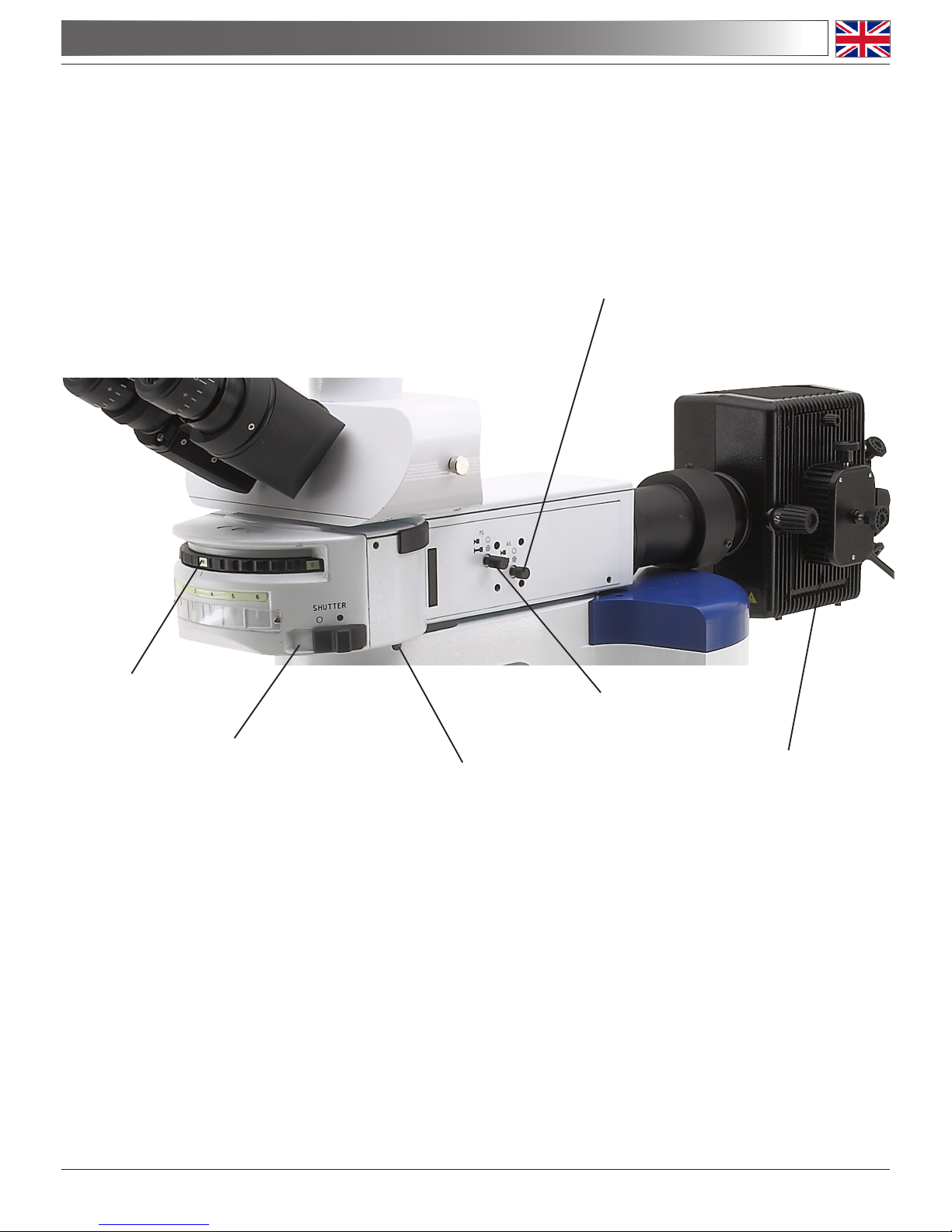
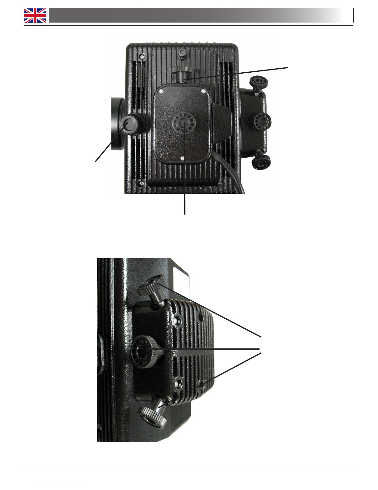
1.0 DESCRIPTION
APERTURE DIAPHGRAM
FILTER WHEEL
FLUORESCENCE LIGHT
SHUTTER
ATTACHMENT FIXING
SCREW
HBO LAMP CASE
FIELD DIAPHGRAM

Page 6
2.0 INTRODUCTION
3.0 UNPACKING AND ASSEMBLY
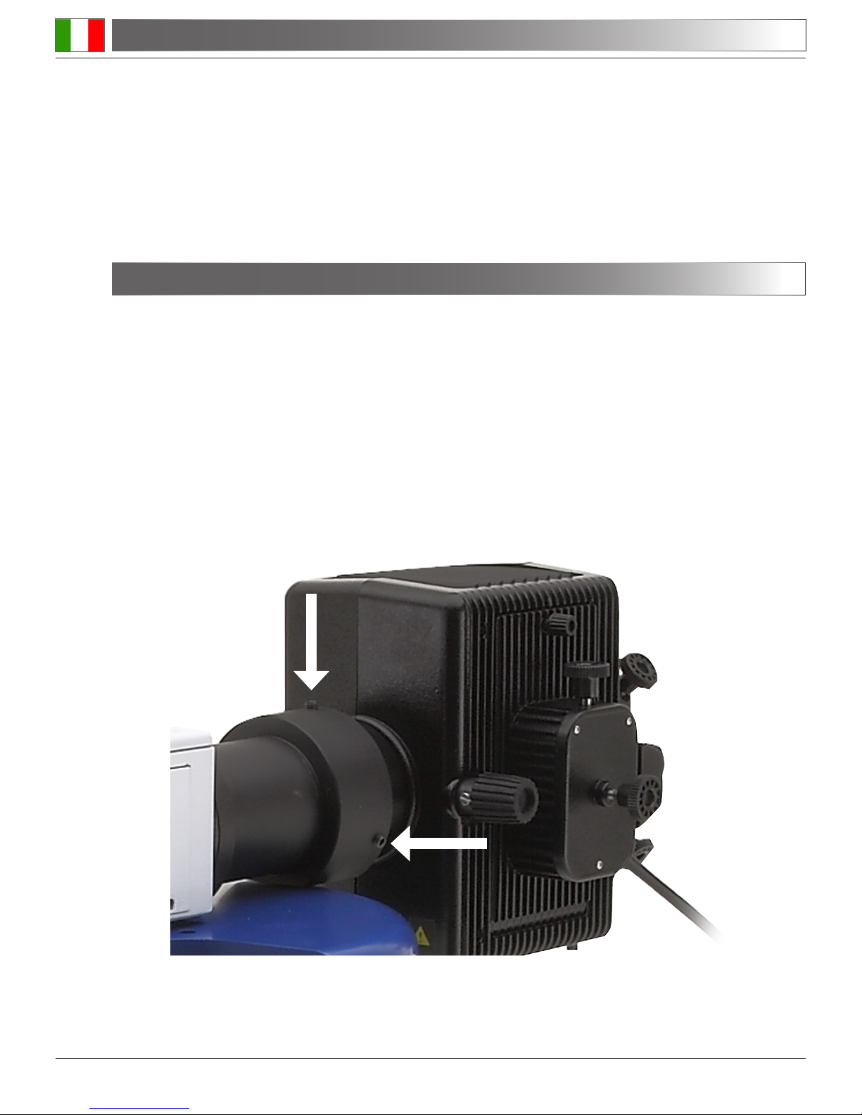
3.1 The components are stored in 2 separated boxes: one containing epiuorescence attachment, and
one containing power supply and mercury lamp case. Remove the protection caps from the top of the
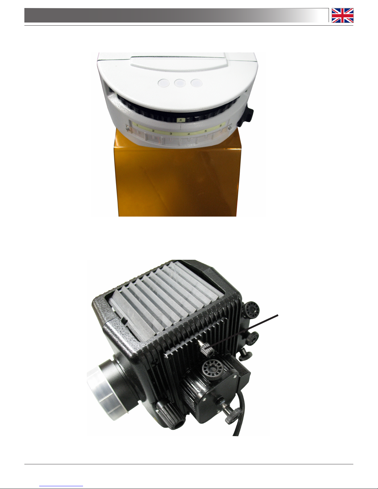
main B-1000 body and from the epiilluminator and place the epiilluminator on the top of the microscope body. Tighten the screw on the right side using the provided allen wrench.
3.2 Insert the mercury lamp case on the back of the epiilluminator and tighten the screws using the provi-
ded allen wrench.
This equipment is a scientic precision instrument designed to last for many years with a minimum of maintenance. It is built to high optical and mechanical standards and to withstand daily classroom and laboratory
use.
Optika reminds you that this manual contains important information on safety and maintenance, and that it
must therefore be made accessible to the instrument users.
Optika declines any responsibility deriving from instrument uses that do not comply with this manual.
Page 7
3.0 UNPACKING AND ASSEMBLY
3.3 Fix the orange protection screen to the front of the epiilluminator with the two provided screws.
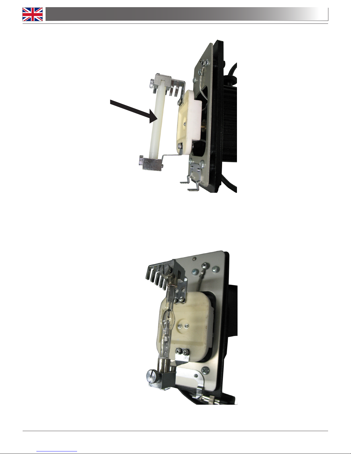
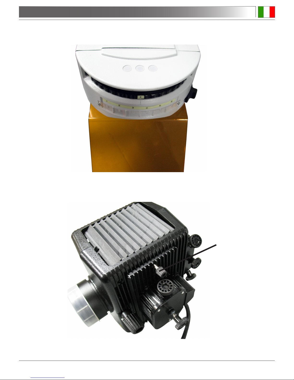
3.4 Mercury lamp insertion: Loosen the lock-screw on the top of the lamp case. The lamp holder will
come out with the door.
Lock screw
Page 8
Remove the plastic placeholder.
Use protection glasses as, if handled carelessly, there is a risk that the lamp may shatter and eject
glass splinters. Thus, without touching the glass part of the lamp, take out the uorescence lamp from
its box, taking care not to exert stress on any part of the lamp. Put one end inside the exible metal
holder (note: it ts only in one direction) and then in the xed one. Tighten the screws just enough to
make it stay in place.If you tighten them too much the lamp may shatter.
Put the lamp door with lamp assembly back in place.
3.5 Connect the lamp case to the power supply trough the provided 3-poles cable.
3.0 UNPACKING AND ASSEMBLY

Page 9
4.1 Turn on the power supply using the power switch. Wait until the current display shows about
4.5 A. If the current falls below 4 A, replace the lamp. You should now wait for at least 10
minutes before aligning and using the lamp.
4.2 Aligning the mercury lamp
Move the lter selector of the lter wheel on the desired position, corresponding to an excitation
wavelength.
Insert a specimen slide and focus with 4X objective.
Fully open the eld and aperture diaphgrams.
Adjust the two lamp centering screws on the case, in order to maximize the light intensity emitted by
the sample.
Adjust the focus of the collector lens until the sample is uniformly illuminated (if the lamp is not cor-
rectly focussed, there will be a bright spot of light in the center of the eld, and dark outside).
Note: if the current display shows 0 A for many seconds after switching on, press the Trigger button
(2-3 times if needed) until a current begins to ow in the lamp.
4.0 USING THE MICROSCOPE
Page 10
The lamp case allows also a ne tuning of the orientation of the mirror located at the back of the
lamp, this could improve the intensity of illumination.
4.0 USING THE MICROSCOPE
Y LAMP MOVEMENT
LENS FOCUS
ADJUSTMENT
X LAMP MOVEMENT
MIRROR ALIGNMENT KNOBS
(ON THE BACK OF LAMP
CASE)

Page 11
4.3 Using the diaphgrams
The illuminator is provided with centrable eld and aperture diaphgrams.
Field diaphgram can be used in order to adjust the area that is being illuminated by the uorescence
light. In this way possible stray light can be controlled.
Aperture diaphgram is used to adjust contrast and depth of eld of the image.
4.0 USING THE MICROSCOPE
FIELD DIAPHGRAM
KNOB
FIELD DIAPHGRAM
CENTRING SCREWS
APERTURE
DIAPHGRAM
KNOB
APERTURE DIAPHGRAM
CENTRING SCREWS

Page 12
5.0 MAINTENANCE
5.1 Always think about
- The following environment is required: Indoor temperature: 0-40°C, Maximum relative humidity:
85% (non condensing).
- Keep the microscope away from dust and shocks while in use.
- Turn off the light immediately after use.
- Use a soft lens tissue to clean the optics after use.
- Only if needed, use a cloth moistened with water and a mild detergent, rinsing with water
and drying immediately with a lint-free cloth.
- After use, cover the microscope with the included dust-cover, and keep it in a dry and clean place.
5.2 Do NOT!
- Wipe the surface of any optical items with your hands. Fingerprints can damage the optics.
- Use solvents, neither on the microscope, nor on the optics.
- Disassemble objective or eyepieces to attempt to clean them.
- Mishandle or impose unnecessary force on the microscope.
- Clean the unit with volatile solvents or abrasive cleaners.
- Attempt to service the microscope yourself.
5.3 Replacement of the halogen lamp
If the maximum current goes down below 4 A the lamp needs to be changed.
The lamp has a lifetime of about 400 hours. In order to avoid explosive failure, replace the lamp
after 400 hours, even if it seems to work correctly.
After the lamp has been switched off it takes about 30 minutes before it is cool enough to be
replaced.
Disconnect any cable from the epiilluminator.
Follow the instructions of point 3.4 Mercury lamp insertion in order to replace the mercury
lamp.
Always use original spare parts for lamp replacement. Do not mount lamps
with different specications or brands.
6.0 ELECTRICAL SPECIFICATION
Fluorescence Power Supply Input: 100 - 240 V, 50/60 Hz
Fuses: T250V 5A
Fluorescence Lamp: HBO 100 W high pressure mercury bulb
Page 13
7.0 RECOVERY AND RECYCLING
Art.13 Dlsg 25 july 2005 N°151. “According to directives 2002/95/EC, 2002/96/EC and 2003/108/EC relating
to the reduction in the use of hazardous substances in electrical and electronic equipment and waste disposal.”
The basket symbol on equipment or on its box indicates that the product at the end of its useful life should be
collected separately from other waste.
The separate collection of this equipment at the end of its lifetime is organized and managed by the
producer. The user will have to contact the manufacturer and follow the rules that he adopted for
end-of-life equipment collection. The collection of the equipment for recycling, treatment and environmentally compatible disposal, helps to prevent possible adverse effects on the environment
and health and promotes reuse and/or recycling of materials of the equipment. Improper disposal of the product involves the application of administrative penalties as provided by the laws in force.


Pagina 15
INDICE
1.0 DESCRIZIONE pag. 17
2.0 INTRODUZIONE pag. 18
3.0 DISIMBALLAGGIO E MONTAGGIO pag. 18
4.0 USO DEL MICROSCOPIO pag. 21
5.0 MANUTENZIONE pag. 24
6.0 CARATTERISTICHE ELETTRICHE pag. 24
7.0 MISURE ECOLOGICHE pag. 25
Pagina 16
Il presente microscopio è uno strumento scientico di precisione studiato per durare molti anni con una manutenzione minima, essendo costruito secondo i migliori standard ottici e meccanici e progettato per un utilizzo
quotidiano.
Optika ricorda che il presente manuale contiene informazioni importanti per un uso sicuro e una corretta manutenzione dello strumento. Esso deve quindi essere accessibile a chiunque lo utilizzi.
Optika declina ogni responsabilità derivante da un uso improprio dei suoi strumenti non indicato dalla presente guida.
Avvertenze di sicurezza
Questo manuale contiene importanti informazioni e avvertenze riguardanti la sicurezza riguardo l’installazione, l’utilizzo e la manutenzione del microscopio. Si raccomanda di leggere attentamente il
manuale prima di qualsiasi utilizzo dello strumento. Per assicurare un utilizzo sicuro l’utente deve
leggere e seguire tutte le istruzioni poste nel presente manuale.
I prodotti OPTIKA sono studiati per un utilizzo sicuro in condizioni operative normali. Lo strumento e
gli accessori descritti nel manuale sono realizzati e testati secondo standard industriali di sicurezza
per strumentazione da laboratorio.
L’utilizzo non corretto può causare lesioni alla persona o danni allo strumento.
Mantenere questo manuale a portata di mano vicino allo strumento, per una facile consultazione.
Precauzioni di sicurezza elettrica
Prima di collegare il cavo di alimentazione alla presa di rete, assicurarsi che la tensione di rete della
vostra regione corrisponda alla tensione di alimentazione dello strumento, e che l’interruttore dell’illuminatore sia in posizione spenta.
L’utente deve osservare la regolamentazione riguardante la sicurezza in vigore nel proprio Stato. Lo
strumento è dotato di marcatura di sicurezza CE, in ogni caso l’utente ha piena responsabilità riguardo all’utilizzo sicuro dello strumento stesso.
Simboli di avvertenza/pericolo usati nel manuale
L’utente deve essere a conoscenza degli aspetti legati alla sicurezza nel momento in cui utilizza lo
strumento. I simboli di avvertenza o pericolo sono indicati sotto. Tali simboli sono utilizzati in questo
manuale di istruzioni.
Seguire le istruzioni contrassegnate da questo simbolo per evitare possibili gravi danni
alle persone.
Avvertimento di utilizzo; la non corretta operazione sullo strumento può causare danni
alla persona o allo strumento.
Possibilità di shock elettrico.
Attenzione: superci ad elevata temperatura. Evitare il contatto diretto.
Note tecniche o consigli di utilizzo.
INDICAZIONI PER LA SICUREZZA
Pagina 17
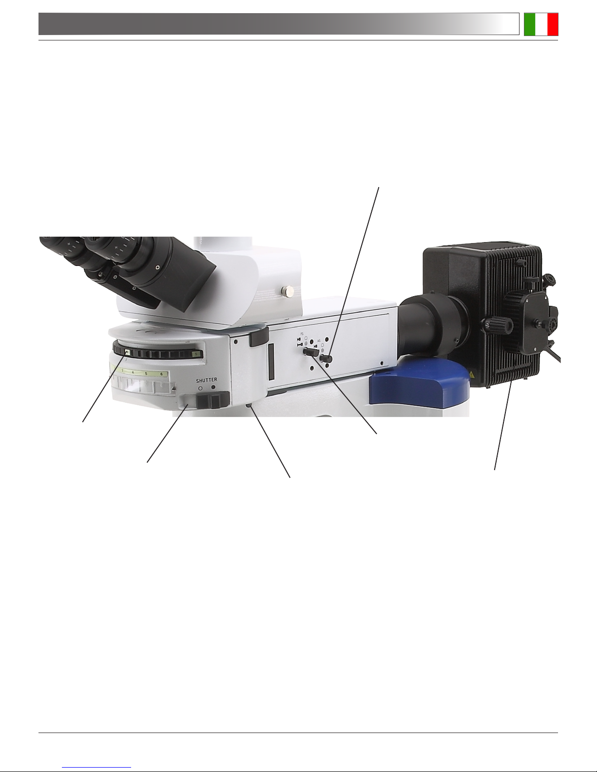
1.0 DESCRIZIONE
DIAFRAMMA D’APERTURA
ROTELLA DEL FILTRO
OTTURATORE PER LUCE
FLUORESCENTE
VITE DI FISSAGGIO
DELL’INSERTO
PORTA LAMPADA HBO
DIAFRAMMA DI CAMPO
Pagina 18
2.0 INTRODUZIONE
3.0 DISIMBALLAGGIO E MONTAGGIO
3.1 I componenti sono conservati in due scatole separate: una contenente un ins erto per epiuorescen-
za, l’altra un alimentatore e una custodia per la lampada al mercurio. Rimuovere i tappi di protezione
dall’epi-illuminatore e dalla parte superiore del corpo principale del B-1000 e posizionare l’epi-illuminatore sulla parte superiore del corpo del microscopio. Serrare la vite sul lato destro utilizzando
l’apposita chiave esagonale.
3.2 Inserire la custodia della lampada al mercurio sul retro del epi-illuminatore e serrare le viti con la chia-
ve esagonale in dotazione.
Questo apparecchio è uno strumento di precisione scientica progettato per durare molti anni con una manutenzione minima. Costruito secondo elevati standard ottici e meccanici, è in grado di resistere all’uso quotidiano in classe e in laboratorio.
Optika ricorda che il presente manuale contiene importanti informazioni sulla sicurezza e sulla manutenzione
e deve pertanto essere messo a disposizione degli utilizzatori dello strumento.
Optika declina ogni responsabilità derivante da un uso dello strumento non conforme al presente manuale.
Pagina 19
3.0 DISIMBALLAGGIO E MONTAGGIO
3.3 Fissare lo schermo di protezione arancione alla parte anteriore del epi-illuminatore con le due viti
fornite in dotazione.
3.4 Inserimento della lampada al mercurio: allentare la vite di bloccaggio sulla parte superiore del portalampada Il portalampada verrà estratto insieme al coperchio.
Vite di bloccaggio
 Loading...