

Optika 2WAJ Operation Manual
OPTIKA MICROSCOPES - ITALY
www.optikamicroscopes.com - info@optikamicroscopes.com
Ver. 4.0.0
OPERATION MANUAL
GUIDA UTENTE
MANUAL DE INSTRUCCIONES
MANUEL D’INSTRUCTIONS
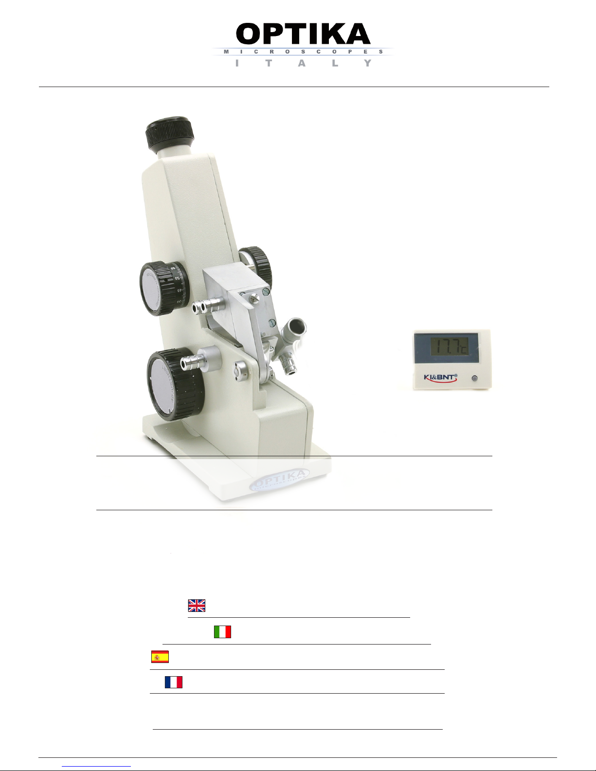
2WAJ

Page 2
INDEX
1.0 DESCRIPTION page 3
2.0 INTRODUCTION page 5
3.0 CONTENTS OF THE SET page 5
4.0 TECHNICAL SPECIFICATIONS page 5
5.0 FUNCTION AND CONSTRUCTION OF THE REFRACTOMETER page 6
6.0 USING THE REFRACTOMETER page 8
7.0 NOTE ABOUT THE MEAN DISPERSION VALUE page 10
8.0 MAINTENANCE page 12
9.0 RECOVERY AND RECYCLING page 13
Page 3
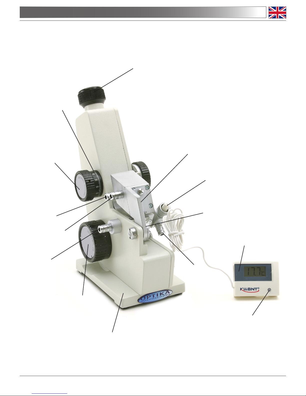
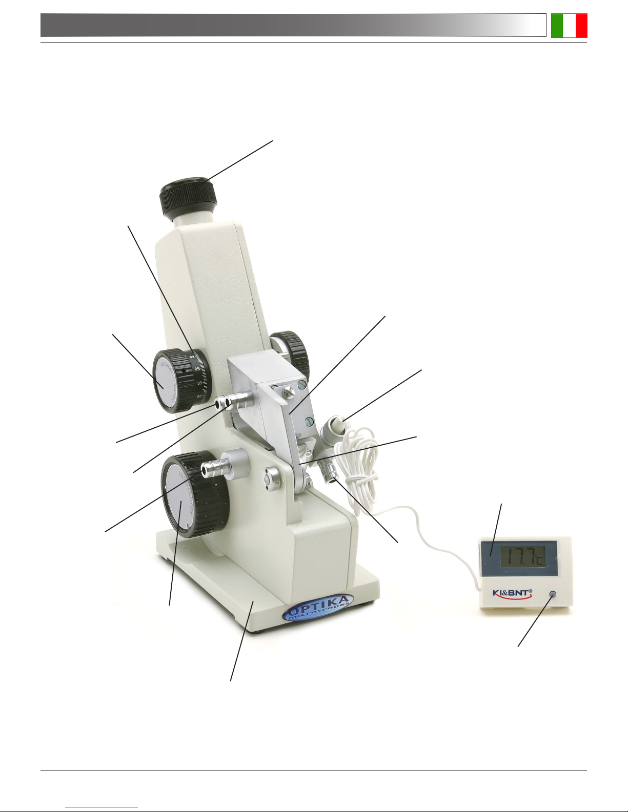
1.0 DESCRIPTION
BRIGHTNESS
ADJUSTMENT KNOB
SYSTEM BASE
EYEPIECE
SHIELD
THERMOMETER
SOCKET
REFLECTING MIRROR
FITTING 1
REFRACTIVE
INDEX GRADUATION
ADJUSTMENT KNOB
FITTING 2
FITTING 4
FITTING 3
DISPERSION
CORRECTION KNOB
DISPERSION SCALE
ON/OFF SWITCH
THERMOMETER

Page 4
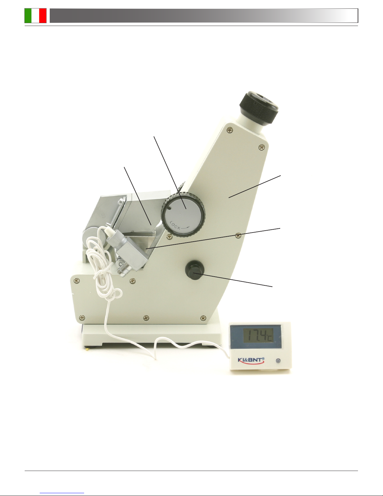
HOUSING
LOCK-KNOB
1.0 DESCRIPTION
REFRACTING PRISM
CONDENSER
INCIDENT PRISM
Page 5
2.0 INTRODUCTION
This refractometer is a scientic precision instrument designed to last for many years with a minimum
of maintenance. It is built to high optical and mechanical standards and to withstand daily use.
The instrument serves for measuring the refractive indices, nD, and mean dispersion values, nF-nC,
of transparent and translucent liquids or solids. Attaching a thermostat to this instrument, the refractive indices, nD, within the range of temperature 0-70°C can be measured.
Refractive indices and mean dispersions are important optical constants of a substance and can
be used to determine the optical performance, purity, concentration and dispersion etc. Therefore,
the refractometer is an indispensable tool within a wide range of industries, such as petrological,
pharmaceutical, chemical and sugar making industries, as well as in factories, colleges and within
research institutes.
Optika reminds you that this manual contains important information on safety and maintenance, and
that it must therefore be made accessible to the instrument users. Optika declines any responsibility
deriving from instrument uses that do not comply with this manual.
ABBE REFRACTOMETER (WITH PLASTIC COVER) 1 SET
SPECIAL THERMOMETER (WITH A BUTTON CELL BATTERY LR 44) 1 SET
CALIBRATION STANDARD 1 PIECE
NAPHTHALENE BROMIDE 1 BOTTLE
SCREWDRIVER 1 PC
INSTRUCTION MANUAL 1 COPY
PRODUCT CERTIFICATION 1 COPY
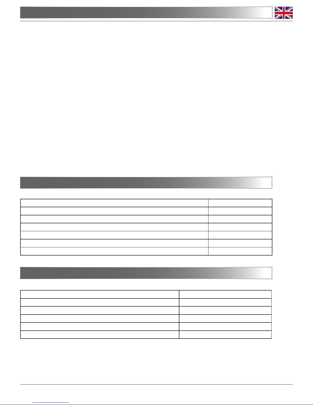
MEASURING RANGE OF ND 1.300-1.700
MEASURING ACCURACY OF ND ± 0.0002
MAGNIFICATION OF TELESCOPIC SYSTEM 2X
MAGNIFICATION OF READING SYSTEM 30X
WEIGHT OF THE INSTRUMENT 2,2 KG
DIMENSIONS OF THE INSTRUMENT 100 X 200 X 240 MM
3.0 CONTENTS OF THE SET
4.0 TECHNICAL SPECIFICATIONS
Page 6
5.0 FUNCTION AND CONSTRUCTION OF THE REFRACTOMETER
5.1 Refractive index
The refractive index of a material is the factor by which the phase velocity of electromagnetic
radiation is slowed in that material, relative to its velocity in a vacuum.
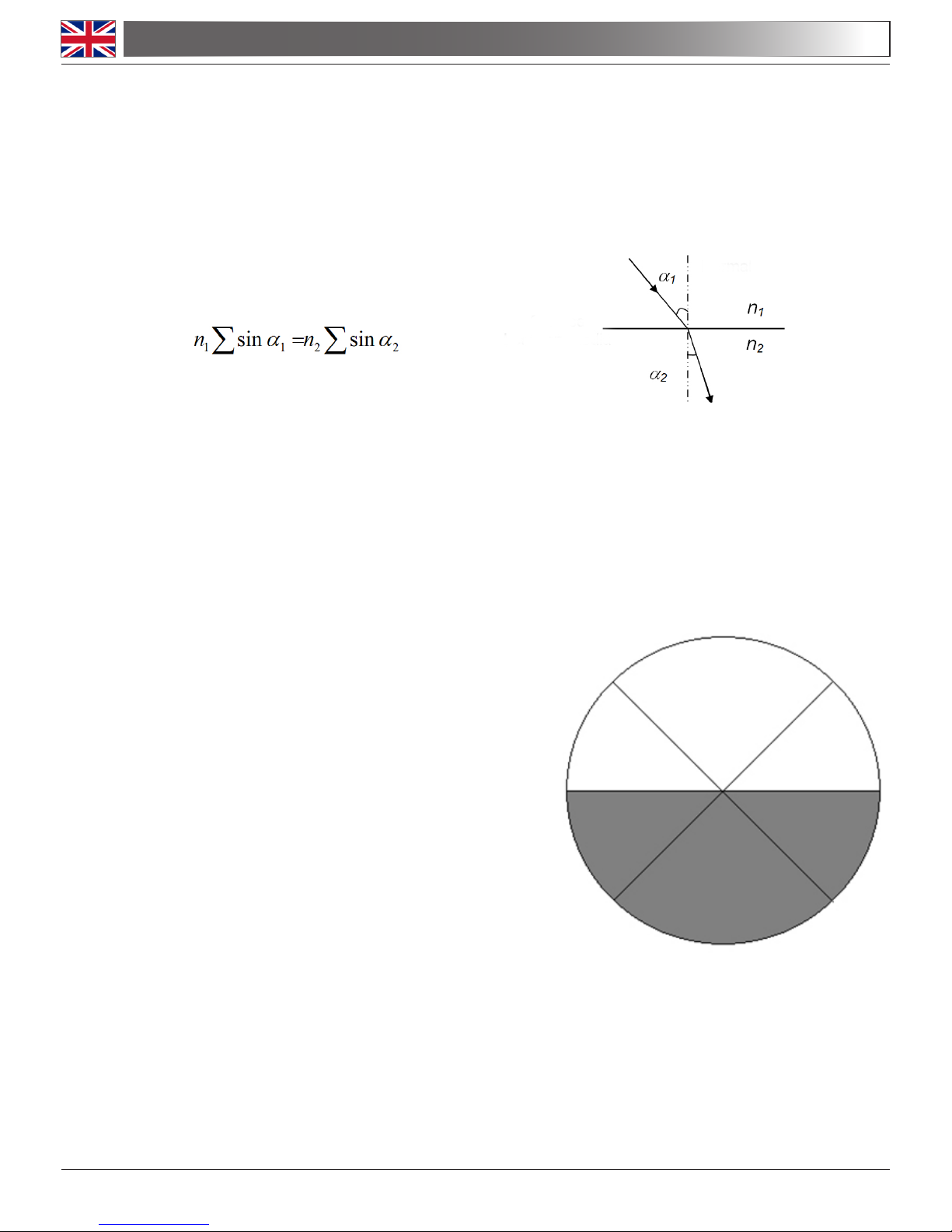
When a light beam travels between two media of differing refractive index, n1 and n2, with an
angle of incidence, a1, that is not perpendicular with the surface, the beam will be deviated
according to the refractive law (Snell’s law):
Where a2, is the angle of refraction measured with respect to the normal to the surface.
When a light beam enters from optically denser medium to optically thinner one, the angle of
incidence is smaller than the refractive angle. Increasing the angle of incidence will lead us to
a point where the angle of refraction will be 90°C. In this case, the angle of incidence is called
a critical angle. Beyond this angle total reection will occur and no light will be transmitted to
the second medium.
This principle is used by the refractometer in or-
der to determine the refractive indices. In the
refractometer light beams from different angles
fall upon the surface, its refractive angles are
always greater than 90°. A telescope is used to
observe the emerging beam and a bright and
dark image can be observed in the eld of view
in the telescope, appearing as distinct boundary
line in between, as indicated in g. 2. The boundary line between the brightness and the darkness is just the position of the critical angle.
5.2 Construction of the optical system
The optical system of the instrument consists of the telescopic and the reading systems as
shown in g. 3. All optical components and other main structures except the prism and the
eyepieces are mounted inside the housing.
Fig.1
Fig.2
NORMAL
SURFACE
BETWEEN MEDIA

Page 7
1. Incident prism 7. Eyepiece
2. Refracting prism 8. Paralleling prism
3. Swingable mirror 9. Reading objective
4. Dispersion compensation prism group 10. Reecting mirror
5. Telescopic objective 11. Scale plate
6. Screen 12. Condenser
Between the incident prism (1) and the refracting prism (2) there exists a minute and homo-
geneous space in which the tested liquid is placed.
When a light beam (daylight or incandescent) enters the incident prism (1) and passes throu-
gh the refracting prism (2), a light beam of which the refracting angles are greater than the
critical angle is produced. The beam will enter via the swingable mirror (3) and travel through
the dispersion free prism group (4).
5.0 FUNCTION AND CONSTRUCTION OF THE REFRACTOMETER
Fig.3

Page 8
5.0 FUNCTION AND CONSTRUCTION OF THE REFRACTOMETER
The dispersion free prism group consists of a pair of equidispersion Amici prisms, and has the
function to obtain a variable dispersion to offset the dispersion resulting from the refractive
prism in relation to the test substance.
Using the telescopic objective (5), the bright/dark boundary line is imaged on the reticule
(6) and can be observed through the eyepiece (7). The scale plate (11) is illuminated by the
daylight from the condenser (12), which connects the scale plate (11).
At the same time the swingable mirror (3) swivels around the graduation centre. The values
of refractive indices of different positions will be imaged on the screen (6) with the help of the
mirror (10), the reading objective (9) and the paralleling prism (8) (as shown on the bottom
part of g. 2).
6.1 Preparations
Calibration
Before measuring, it is necessary to calibrate the instrument using the calibration standard (a
glass block with a known refractive index) that comes with the instrument.
Then do the following:
- Open the refracting prism.
- Drop one or two drops of naphthalene bromide on the surface of the glass block.
- Place the specimen on the incident prism.
- Adjust the eyepiece to focus the visual eld.
- Adjust the dispersion correction knob until it is possible to distinguish two separate elds, one
light one and one darker.
- Use the refractive index graduation adjustment knob to move the separation line between the
two elds until it is exactly where the two diagonal lines intersect.
- Read the refractive index from the lower scale.
- If the reading is not accurate with the index printed on the standard specimen, adjust the regulation screw at the back of the instrument.
- Warning: The naphthalene bromide must be wiped off as soon as possible after the measurement as it may damage the prism.
If there is any doubt about the determined refractive index during routine testing work, the
above-mentioned methods can be used for correction.
Cleaning
Before measuring and doing the calculation, the rough surface of the incident prism, the po-
lished surfaces of the refracting prism and the standard specimen should be cleaned with a
piece of absorbent cotton dipped with a 1:1 absolute alcohol and ether solution to remove dirt
which can affect image sharpness and measuring accuracy.
6.0 USING THE REFRACTOMETER

Page 9
6.2 Measuring
Testing transparent and translucent liquid
- Drop the liquid to be tested onto the surface of the prism, then cover the incident prism and
lock with the knob. Verify that the liquid layer is homogeneous, without bubbles and has been
spread over the whole eld of view.
- Open the shield and close the reecting mirror.
- Adjust the eyepiece to focus the visual eld.
- Adjust the dispersion correction knob until it is possible to distinguish two separate elds, one
light one and one darker.
- Use the refractive index graduation adjustment knob to move the separation line between
the two elds until it is exactly where the two diagonal lines intersect. If needed, adjust the
condenser.
- At this point, the refractive index of the tested liquid can be read from the lower scale.
Testing transparent solids
To test a transparent solid object it needs to have a smooth polished surface. Open the
incident prism and add one or two drops of naphthalene bromide onto the smooth plane of
refracting prism, then clean the polished surface of the tested object so that it can contact
better, when the work looking for the boundary line in the eyepiece can be conducted. Follow
the procedure for aiming and reading as described above.
Testing translucent solid
One surface of the translucent solid should be a polished plane, upon which naphthalene
bromide should be dropped, then put it with the naphthalene bromide side on the refracting
prism. Open the reecting mirror, adjust the angle, and use it as a surface of incidence for the
measurement. Follow the operation procedure as described above.
Testing the sugar concentration of sugary liquid
Above the refractive index scale, the instrument shows the corresponding Brix values (sugar
concentration in water). In order to read such scale, operate as for measuring the refractive
index measurement in any other liquid.
Determining mean dispersion value
This procedure is similar to determining the refractive index. Turn the dispersion correction
knob until the colours around the bright and dark boundary line in the eld of view disappears.
Then read the value Z at the dispersion scale and its refractive index nD of the scale in the
eld of view. Using the measured value of nD, nd the corresponding value of A and B from
Table 1. If nD lies in between two gures, it can be found by interpolation. Then nd the corresponding value of 0 from Table 1 according to the value Z. When Z>30, use negative sign,
When Z>30, use positive sign. The mean dispersion value can be calculated by using the
found values of A, B and 0 in the dispersion equation (see example under “Note on mean
dispersion value”).
Measuring the refractive index at different temperatures
To measure the refractive indices at various temperatures, connect a recirculation thermostat
to the ttings. The thermostating liquid should enter from tting 1 (see gure under “Description”) and the tting 2 should be connected to tting 3. Fitting 4 is the output tting. Insert the
thermometer into its socket and switch it on. Wait until the temperature stabilizes and begin
the measurements.
6.0 USING THE REFRACTOMETER

Page 10
7.0 NOTE ABOUT THE MEAN DISPERSION VALUE
Example:
Calculating the mean dispersion of distilled water
The refractive index, nD = 1.3330 at 20° C
The readings taken from the dispersion scale are:
Rotating in one direction Rotating in the opposite direction
41.7 41.5
41.6 41.6
41.6 41.6
41.6 41.7
41.7 41.6
The mean values are: 41.64 and 41.6 and the mean values of these give Z = 41.62
Looking in Table 1 interpolating when nD = 1.3330 we nd that
A=0.0248 15 and B = 0.033056
When Z = 41.62
0 = -0.5716 (because Z>30, 0 will have negative sign (-))
The mean dispersion value of distilled water can now be calculated according to the formula
(see Table 1):
nF - nc = A + B*0 = 0.024815 - 0.033056 x 0.5716 = 0.00592

Page 11
7.0 NOTE ABOUT THE MEAN DISPERSION VALUE
Table 1: Dispersion Table for Abbe Refractometer Formula for calculation of the mean disper
sion value: nF-nC = A + B*0
The reading of the 0’s for the corresponding Z of all compensators takes positive sign
(+) when Z<30, and takes negative sign (-) when Z>30.

Page 12
- The following environment is required: Indoor temperature: 0-40°C, Maximum relative humidity: 85 % (non condensing)
- After use, the instrument must be cleaned and stored in a dry, well-ventilated and clean place.
Use the dust cover and the desiccant.
- After dealing with corrosive liquid the cleaning should be done immediately after use in time
to prevent from corrosive damage on the optical and mechanical parts as well as the painted
surface.
Warning: If left on, naphthalene bromide may corrode the prisms.
- Verify that no hard contaminant is left in the sample during the test. When using a solid test
sample, be sure not to scrape or damage the prism surface.
- The instrument should always be kept clean. Never touch the optical parts with your ngers.
Cleaning of the optical parts may be done by rubbing lightly with a piece soft lens tissue or
absorbent cotton, then blow it dry with a blow drier. Only if needed, use a cloth moistened with
water and a mild detergent, rinsing with water and drying immediately with a lint-free cloth.
- Smears on the optical surface can be removed in time using xylene or ether.
- The instrument should be protected against drastic vibration and impact to prevent the optical
parts form being damaged, which will affect the testing accuracy.
- Do not attempt to service the refractometer yourself.
How to change the batteries of the thermometer
The thermometer uses one button cell battery, LR 44. To change the battery, remove the door
on the back of the thermometer, remove the old battery, replace it with a new one and replace
the door.
Warning: Batteries are dangerous to the environment. Discard them as required by the law.
8.0 MAINTENANCE
Page 13
Art.13 Dlsg 25 july 2005 N°151. “According to directives 2002/95/EC, 2002/96/EC and 2003/108/EC
relating to the reduction in the use of hazardous substances in electrical and electronic equipment
and waste disposal.”
The basket symbol on equipment or on its box indicates that the product at the end of its useful life
should be collected separately from other waste.
The separate collection of this equipment at the end of its lifetime is organized and managed by
the producer. The user will have to contact the manufacturer and follow the rules that he adopted
for end-of-life equipment collection. The collection of the equipment for recycling, treatment and en-
vironmentally compatible disposal, helps to prevent possible adverse effects on the environment
and health and promotes reuse and/or recycling of materials of the equipment. Improper disposal
of the product involves the application of administrative penalties as provided by the laws in force.
9.0 RECOVERY AND RECYCLING

Pagina 14
INDICE
1.0 DESCRIZIONE pag. 15
2.0 INTRODUZIONE pag. 17
3.0 CONTENUTO DEL KIT pag. 17
4.0 SPECIFICHE TECNICHE pag. 17
5.0 FUNZIONAMENTO E STRUTTURA DEL RIFRATTOMETRO pag. 18
6.0 UTILIZZO DEL RIFRATTOMETRO pag. 20
7.0 NOTA SUL VALORE DI DISPERSIONE MEDIO pag. 22
8.0 MANUTENZIONE pag. 24
9.0 MISURE ECOLOGICHE pag. 25
Pagina 15
1.0 DESCRIZIONE
BRIGHTNESS
ADJUSTMENT KNOB
BASE
OCULARE
SCHERMO
SUPPORTO PER
TERMOMETRO
SPECCHIO
RIFLETTENTE
RACCORDO 1
MANOPOLA DI
REGOLAZIONE
DELLA SCALA INDICE
DI RIFRAZIONE
RACCORDO 2
RACCORDO 4
RACCORDO 3
MANOPOLA DI CORREZIONE
DELLA DISPERSIONE
SCALA DISPERSIONE
INTERRUTTORE
ON/OFF
TERMOMETRO
Pagina 16
INVOLUCRO
MANOPOLA DI
BLOCCAGGIO
1.0 DESCRIZIONE
PRISMA RIFRANGENTE
CONDENSATORE
PRISMA INCIDENTE
 Loading...