

Opticstar AZ80-GOTO, AZ90-GOTO Instruction Manual

Instruction Manual for Opticstar AZ80-GOTO and
AZ90-GOTO Computerised Telescopes
© Copyright Opticstar Ltd 2014 0

C
AUTION!
Never look at the Sun through your telescope or through the
telescope’s finder as this will cause blindness. Observing the
Sun directly, even for a very short period, without the
appropriate protection can cause serious damage to your eyes.
© Copyright Opticstar Ltd 2014 1

IMPORTANT INFORMATION
Please keep this instruction manual handy and always use the telescope as described in
ope
Never disassemble the telescope, there are no serviceable parts inside. Disassembling the
telescope will invalidate your warrantee and may cause damage or injury. In the event of a
ontact your dealer. Children should always use this telescope under the
The telescope has been designed primarily for astronomical observing. It can be used once
a table without the supplied tripod.
Do not leave the telescope under direct Sunlight as this can damage the scope and the
to the Sun through your telescope or through the telescope’s
finder as this will cause permanent blindness. Always use the appropriate protection to
you intend to observe the Sun with a telescope,
never use Solar filters that can be attached to the eyepiece end, they are unsafe and can
Use the telescope as described in the manual. Do not disassemble the telescope as there
is a risk of electric shock. The telescope is powered by 8 x AA batteries, always use the
Damaged, old and discharged batteries can leak acid and cause burns if improperly
handled. Always handle and dispose batteries with care. Never heat up or throw batteries
The Instruction Manual
this manual. Read the safety instructions below carefully to avoid damage to the telesc
and to avoid injury to yourself and others.
Attention
defect please c
supervision of adults.
Intended Use
attached to its tripod or alternatively it can be used on
optics, in addition the telescope can focus Sun light into point and cause a fire.
Observing the Sun
Never look at the Sun or close
observe the Sun through a telescope or through the naked eye.
Always use a full aperture Solar filter if
result in damaging both your eyes and the telescope.
Chocking Hazards
Keep small parts, plastic bags and other packaging materials out of the reach of children.
Electric Hazards
recommended batteries and make certain that the batteries have been inserted correctly.
Batteries
into a fire as this can cause an explosion.
Opticstar Ltd
87 Washway Road, Sale, Greater Manchester, M33 7TQ. United Kingdom
Web: www.opticstar .com – Email: info@opticstar.com
© Copyright Opticstar Ltd 2014 2
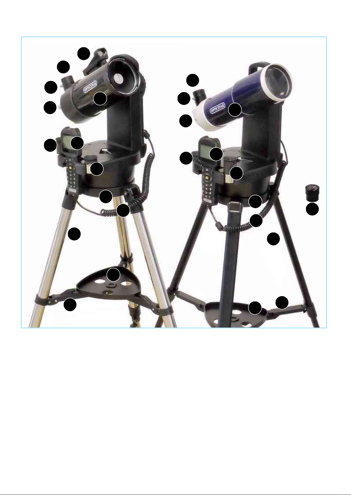
AZ90-GOTO & AZ80-GOTO Overview 1/2
AZ90 GOTO Telescope Parts
AZ80 GOTO Telescope Parts
112233445667788991010111112121313
AZ90 GOTO
AZ80 GOTO
14
1. Optical Tube & Lid (not shown)
2. Eyepiece Drawtube
3. Locking Screw
4. Focus Knob
5. Red Dot Finder
6. Tripod
7. Tripod Platform
8. Leg Spreader
9. Accessory tray
10.1.25” 10mm eyepiece
11.1.25” 25mm eyepiece
12.Handset
13.Handset cable
14.Bubble level & Compass Accessory
15.This Instruction manual
1. Optical Tube & Lid (not shown)
2. Eyepiece Drawtube
3. Locking Screw
4. Focus Knob
5. N.A.
6. Tripod
7. Tripod Platform
8. Leg Spreader
9. Accessory tray
10.1.25” 10mm eyepiece
11.1.25” 25mm eyepiece
12.Handset
13.Handset cable
14.Bubble level & Compass Accessory
15.This Instruction manual
© Copyright Opticstar Ltd 2014 3

AZ90-GOTO & AZ80-GOTO Overview 2/2
Carry Handle
AUX Auxiliary Port
Hand Screw
MOUNT-HEAD
Telescope Saddle
Battery Compartment
Eyepiece Holder 1
Handset Holder
Eyepiece Holder 2
Azimuth Lever
(locked position)
Red LED torch
to unlock
to unlock
Altitude Knob
ON/OFF Switch
HBX Handset Port
5VDC Power Output
12VDC Power Socket
LED Display
GOTO HANDSET
LED Torch Switch
Arrow Keys Confirm Key
Help Key
Mini USB Port
RJ-45 Handset Port RJ-22 Port
© Copyright Opticstar Ltd 2014 4
+ & - Keys
Alpha-numeric pad

Telescope Assembly
You will need a fair amount of space to unpack the parts and assemble the telescope. You will also need a surface
like a table to rest the parts and this manual during assembly. You may want to lay a tablecloth or similar over the
table to protect the surface.
Start by carefully removing all the parts from their packaging and laying them out on the table. Use the diagrams on
the previous pages to check that no parts are missing. Look carefully through the packaging materials as it is
sometimes easy to miss smaller parts.
Pick up the tripod and slowly pull the legs apart. Never force the legs open as this can damage the tripod.
Place the open tripod on a flat floor. Place the Accessory Tray centrally on the Leg Spreader so that it fits and turn it
clockwise until it locks in place. Never collapse the tripod without removing the Accessory Tray first, always remove
the Accessory Tray before collapsing the tripod
Place the Mount-Head on its tripod making certain that the threaded mounting holes on the base of the Mount-Head
match the two screws on the Tripod Platform. Now hand-tighten the screws to secure the Mount-Head on its tripod. It
is worth periodically checking that these screws remain tight.
Loosen the Altitude Knob with your hand by rotating it counter-clockwise,
then rotate the Telescope Saddle until the hand-screw points upwards
and tighten the altitude knob by rotating it clockwise.
Loosen the hand screw on the Saddle so that it does not protrude. Place
the Optical Tube in the Saddle and tighten the hand screw firmly to
secure the Optical Tube as shown in the picture on the right. Make
certain the Optical Tube is horizontal to the floor. You can reset its
position by loosening the Altitude Knob, adjusting the position of the
Optical Tube and re-tightening the Altitude Knob.
Pick up the 25mm eyepiece that came with the telescope and remove the covers at either end. Remove the dustcover from the Eyepiece Drawtube near the back of the Optical Tube and loosen the eyepiece Locking Screw so that
it does not protrude in the inside of the Eyepiece Drawtube. Place the 25mm eyepiece in the Eyepiece Drawtube and
finger-tighten the Locking Screw to secure the 25mm eyepiece in place. Remove the Optical Tube Lid and make
certain that you do not point the Optical Tube to or near the Sun.
To get an object in clear view you will need to first focus the telescope. With an eyepiece in place point the telescope
to a landmark far away and turn the Focusing Knob on the back of the Optical Tube a number of times to bring the
target into focus. If you feel mounting resistance while turning the Focusing Knob it means that it has come to the end
of its travel. Simply turn the Focusing Knob the other way to reach focus and assuming that the target is within focal
range. Keep in mind that the minimum focusing distance for the telescope is over 20 meters.
Eyepieces with longer focal lengths (i.e. 25mm) will offer lower magnifications and wider fields of view. Low power
eyepieces are well suited for locating targets and for focusing the telescope. Once the target is in clear view place it in
the centre of the field of view and replace the 25mm eyepiece with a 10mm eyepiece, this will increase magnification
by 2.5 times and decrease the field of view by a similar amount. Changing to different eyepiece may require
refocusing the telescope by around half a turn of the Focusing Knob, clockwise or counter-clockwise.
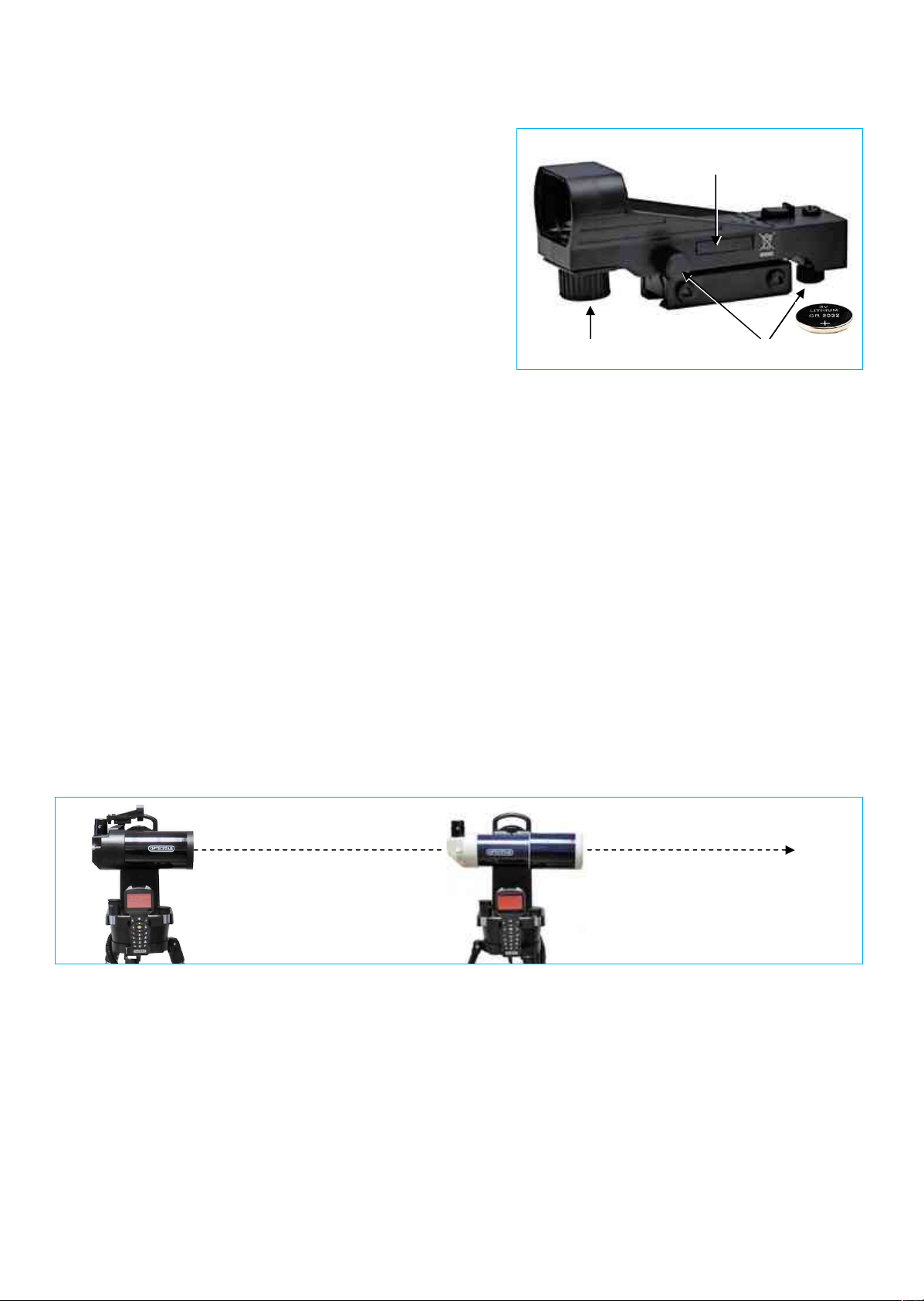
Red Dot Finder
If your telescope has a Red Dot Finder (RDF) you would need to
mount in on the back of the Optical Tube as seen in the image on the
right. Because the AZ90 GOTO telescope has a relatively long focal
length, and is capable of high magnifications, its field of view is
relatively small. This can make it hard to know where the telescope is
pointing. The Red Dot Finder makes pointing your telescope easy.
RDF fixing screw
To switch on the Red Dot Finder, rotate the Power Knob clockwise
until it clicks on. Turning the Power Knob clockwise increases the dot
brightness, anticlockwise reduces the dot brightness.
Adjust the brightness of the red dot so that it can just be seen so as
not obscure faint nearby stars when observing the night sky.
© Copyright Opticstar Ltd 2014 5
Once the RDF has been fitted it would need to be aligned to the Optical Tube so that both the Optical Tube and RDF
point to the same direction. Point the telescope to a target a few miles away and centre the target in the field of view
using a high power eyepiece (i.e. 10mm).
Switch on the RDF and place your head around 30cm (12”)
behind it. Look through the RDF with both eyes open until you
see a bright red dot superimposed on your view. Without moving
Battery Compartment
the telescope, adjust the two Adjustment Screws until you have
placed the red dot on the object you were looking at.
You can now easily point the telescope to distant targets with the
aid of the RDF.
The Red Dot Finder requires a single CR2032 type battery to
operate. To replace the battery use a pen to push out the sliding
battery tray before removing it completely. Replace the battery
and slide the battery tray back in place. Please note that with
Power Knob Adjustment Knobs
regard the battery’s polarity the positive side should face up.
Powering the Telescope
To power the telescope you will need 8 1.5VDC AA type batteries. We recommend high quality batteries including
Alkalines. Rechargeable batteries do not provide enough power over a period. If you decide to use AA rechargeable
batteries they will need to be of high capacity and quality. To insert the batteries first check that the ON/OFF telescope
power switch is at the OFF position. Locate and remove the rectangular Battery Compartment cover on the top side of
the Mount-Head's base, this will reveal the battery holder. Remove the battery holder and insert eight AA batteries into
it observing the polarity, replace the battery holder and close the Battery Compartment cover.
The telescope requires 12VDC to operate. Never use batteries or any power source at Voltages above 12VDC as this
can seriously damage the telescope and invalidate the warranty.
Aligning the Telescope
Your telescope should now be fully assembled and ready to use for the first time. The next few pages take you
through the process of setting up, Star-Aligning and using your telescope for the first time, i.e.
1. Set the telescope to the Home Position.
2. Enter the data required in the handset.
3. Star Align the telescope
4. Issue GOTO commands to the telescope.
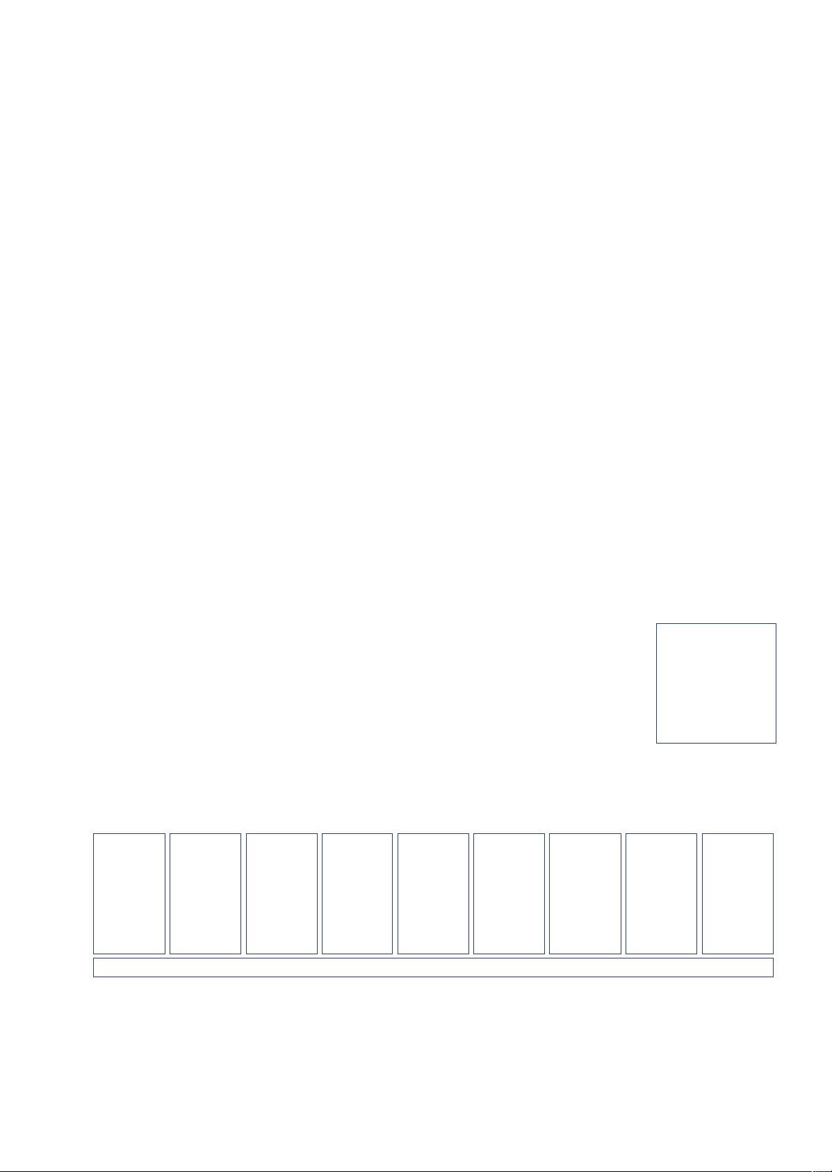
Home Position
Use the supplied compass/bubble-level accessory in order to set the telescope to its Home Position.
North
AZ90-GOTO Home Position AZ80-GOTO Home Position
1. Place the bubble-level on the top side of the mount's base and level the mount by adjusting the tripod legs.
2. Place the bubble-level in the place of the eyepiece and level the Optical Tube by loosening the large round
Altitude Knob found on the side of the Mount-Head's arm, then re-tighten the Altitude Knob.
3. Loosen the silver Azimuth Locking Lever on the upper base of the mount-head and with the help of the
compass point the optical tube North, re-tighten the Azimuth Locking Lever (red compass arrow points North).
4. Remove the compass/bubble-level and place the 25mm eyepiece in the eyepiece drawtube, secure it in place.
5. Remove the lid from the front of the telescope.
You are now ready to input your location/site data into the handset and Star-align your telescope.
© Copyright Opticstar Ltd 2014 6
Telescope Handset Setup and Telescope Star-Alignment
Name:
London
D
ate: 12
:01:201
4 (mm/dd/yyyy)
Time:20:10:00
Daylight Saving: OFF
Name:
Birmin
gham
Cardiff
Edinburgh
Leeds
Liverpool
London
Manchester
Newcastle
Ipswich
The following text describes the procedure of setting up the handset and aligning your AZ-GOTO telescope. The
diagram in page 9 outlines the same but in a concise graphical form.
Handset Setup
With the power switch in the OFF position insert 8 AA batteries into the battery holder or connect the telescope to a
regulated mains PSU (12VDC ~1A, pin positive).
Plug one end of the coiled RJ-45 cable in the port labelled HBX on the telescope panel and the other one into the RJ45 port of the handset. Switch ON the telescope. The handset will light up accompanied by a short beep.
Please note that that the + and – keys on the handset keypad can be used to navigate the menus. Pressing the – key
for example a few times will get you to the Main menu from where you can issue GOTO commands once the
telescope has been Star Aligned.
Time & Date
You will be prompted to enter the date and time. Do so by navigating the entry fields using the Arrow Keys and typing
in the values using the numeric pad on the handset. Once finished, press the oval Confirm Key to proceed.
Daylight Saving
Use the Up/Down Arrows to select Daylight Saving time by selecting the status (ON/OFF). Press the Confirm Key to
proceed.
Location
When prompted to enter your location you can either select a city (Country &City) close to you or directly enter your
GPS coordinates in terms of Longitude and Latitude (Custom Site). Press the Confirm Key to proceed.
Selecting: Country & City
To select a city close to you select the Country & City option. Select the country with the Up/Down Arrow Keys and
then the city with the Left/Right Arrow Keys. Once you have made your choice press the oval Confirm Key to proceed.
Selecting: Custom Site
To set you own Custom Site instead, enter the Site details as follows:
Name: custom name for your location London
Lon: your location’s longitude in: degrees:minutes:seconds W 0o05’ = E 359o55’
Lat: your location’s latitude in: degrees:minutes:seconds N 51o32’
Zone: your time zone in: hours:minutes:seconds UK: 00:00:00
OTA: 0 0
Azi: 000 000
Alt: 00 00
The Azi (Azimuth) and Alt (Altitude) values define the starting position (Home Position) of your telescope prior to
alignment; at 000/00 the telescope should point North (000) and the optical tube should start level to the ground (00).
For example if the telescope was in a location listed below on the 1stof December 2014, the time was 8:10pm, the
telescope was pointing North and the optical tube was level the inputs list would look as follows:
Lon:
Lat:
Zone:
OTA:
Azi:
Alt:
358o07’
52o29’
00:00:00
00
000
00
356o49’
51o29’
00:00:00 0
000
00
356o43’
55o57’
00:00:00 0
000
00
358o27’
53o48’
00:00:00 0
000
00
357o00’
53o24’
00:00:00 0
000
00
359o55’
51o32’
00:00:00 0
000
00
357o45’
53o30’
00:00:00 0
000
00
Lon: E359:55
Lat: N51:32:00
Zone: E00:00:00
OTA: 0
Azi: 000
Alt: 00
358o23’
54o58’
00:00:00 0
000
00
1o09’
52o04’
00:00:00 0
000
00
Please note that if your location is West of Greenwich (Greenwich longitude: 000o00’) the value would be negative i.e.
-0o.5’ or 0o5’ West. Since the handset expects a positive value between 0-360 this can be calculated by subtracting
the value you want from 360, i.e. 360o0’ - 0o5’=359o55’ as in the previous ’London’ example.
Please remember that the telescope expects the Longitude and Latitude in degrees:minutes:seconds and not in
decimal form.
€ Copyright Opticstar Ltd 2014 7
 Loading...