

Page 1

Setup Manual
Opticstar 318CU-T 3.0MP and
Opticstar 518CU-T 5.0MP
Colour Hi-speed Video Cameras
OPTICSTAR
Page 2

1
Page 3

2
Contents
Contents..........................................................................................................................................2
Software Installation .......................................................................................................................3
Troubleshooting..............................................................................................................................7
Camera Performance.......................................................................................................................9
Micrometrics BE: CMOS Cameras Edition................................................................................... 10
User Interface............................................................................................................................10
Commands and Options - Camera Control ................................................................................10
Commands and Options - Imaging Control................................................................................12
Opticstar Ltd,
87 Washway Road, Sale, Greater Manchester, M33 7TQ United Kingdom.
Tel: +44(0)161 969 9008 - Web: www.opticstar.com - Email: [email protected]
OPTICSTAR
Page 4
3
Software Installation
Before you start please make certain that:
1. Your camera is not connected to your computer.
2. Your computer has a USB2.0 port.
3. Your computer runs Windows 2000, Windows XP or Windows Vista.
4. Stop any virus killer software or similar as they may affect the
installation process and affect the speed at which the camera operates.
To successfully install the Micrometrics software please follow the instructions
below:
1. Disconnect the camera from your computer
2. Insert the CD that came with your camera in a CD drive.
3. Double click on the CD icon to view the contents of the CD.
4. Double-click on the Setup_XP.exe or Setup_Vista.exe icon to start
installing the Micrometrics software on Windows 2000/XP or Windows
Vista respectively.
5. Follow the on-screen instructions to install the software.
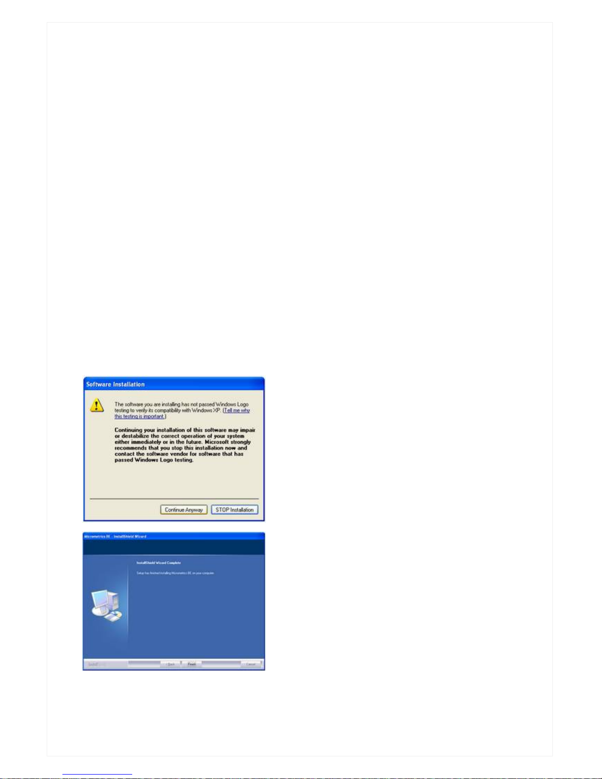
If this screen appears during the
installation please click on Continue
Anyway
Click on Finish to complete the camera
control software installation.
You will now need to install the camera drivers before your camera becomes
operational.
Page 5
4
122CU
316CU
318CU
516CU
Once the Micrometrics software have been successfully installed:
1. Connect the camera to the USB port.
2. Windows will identify the camera and attempt to find a suitable driver for
your camera.
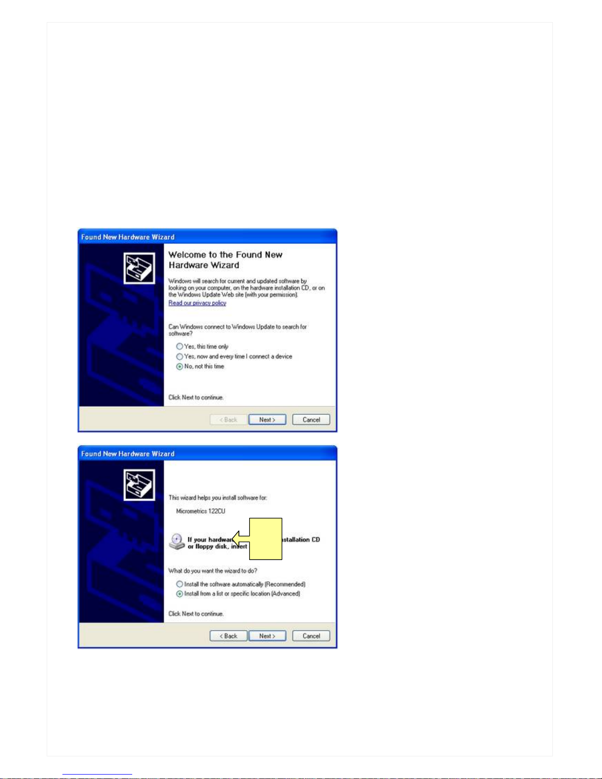
A number of screens will appear during installation that will require your input.
Please follow the instructions below for a trouble-free installation.
Once you have made a selection as in the screens below press Next to move
to the next screen.
Windows will start installing the software for your camera.
Page 6
5
122CU
316CU
318CU
516CU
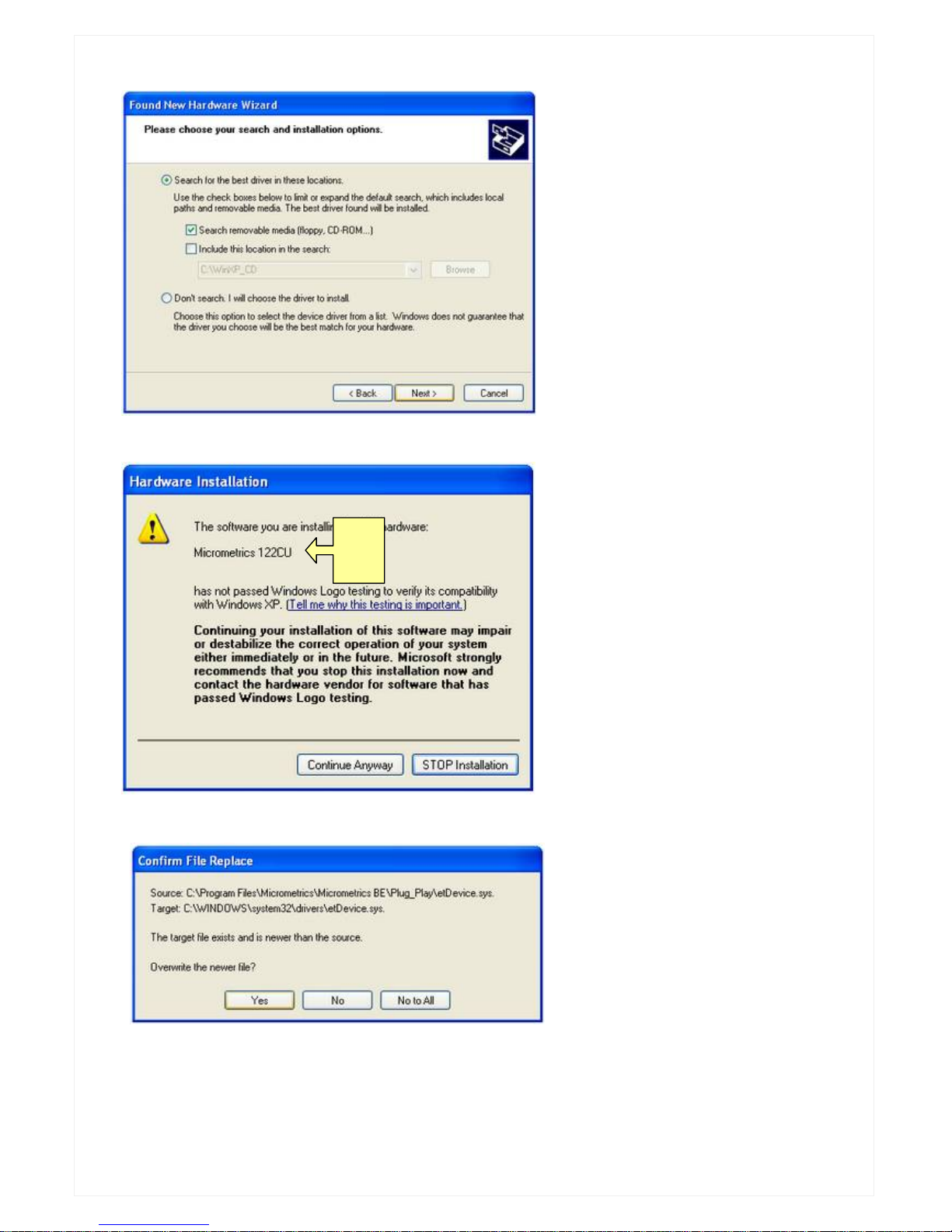
Please make your selections
as on the screen on the left.
Click on Next to continue.
You may see the following
screen.
If this screen appears click on
Continue Anyway.
Windows will continue with the
installation.
If this screen appears (it may
appear more than once) click
on Yes.
Page 7
6
122CU
316CU
318CU
516CU
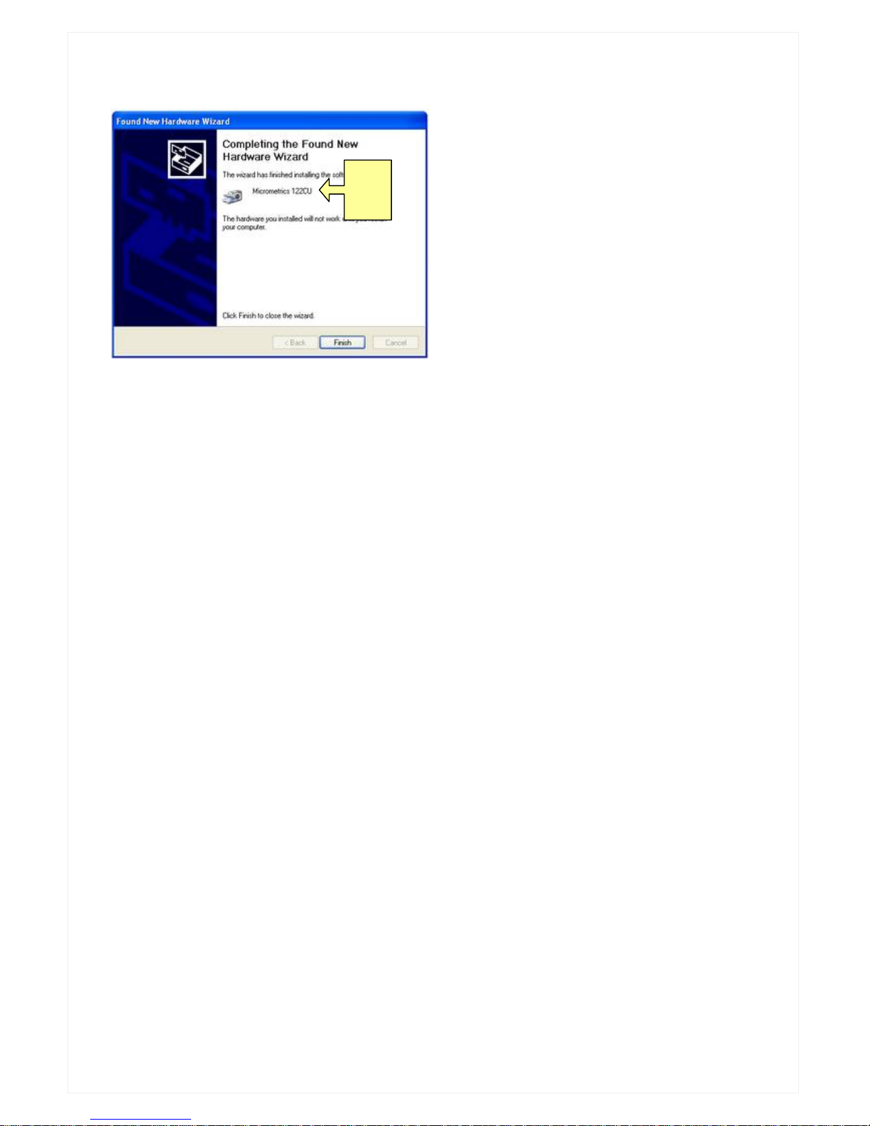
Click on Finish to complete driver
installation.
You will be prompted by Windows to reset your PC for the changes to take
effect. Make certain that you save any work, close all applications and reboot
your PC.
3. Once Windows has installed the drivers for your camera and you have
reset your PC you will be able to run Micrometrics BE for the first time.
NOTE: Micrometrics software require Micrometrics compatible camera and
will not operate if such a camera is not connected to your PC.
Page 8
7
Troubleshooting
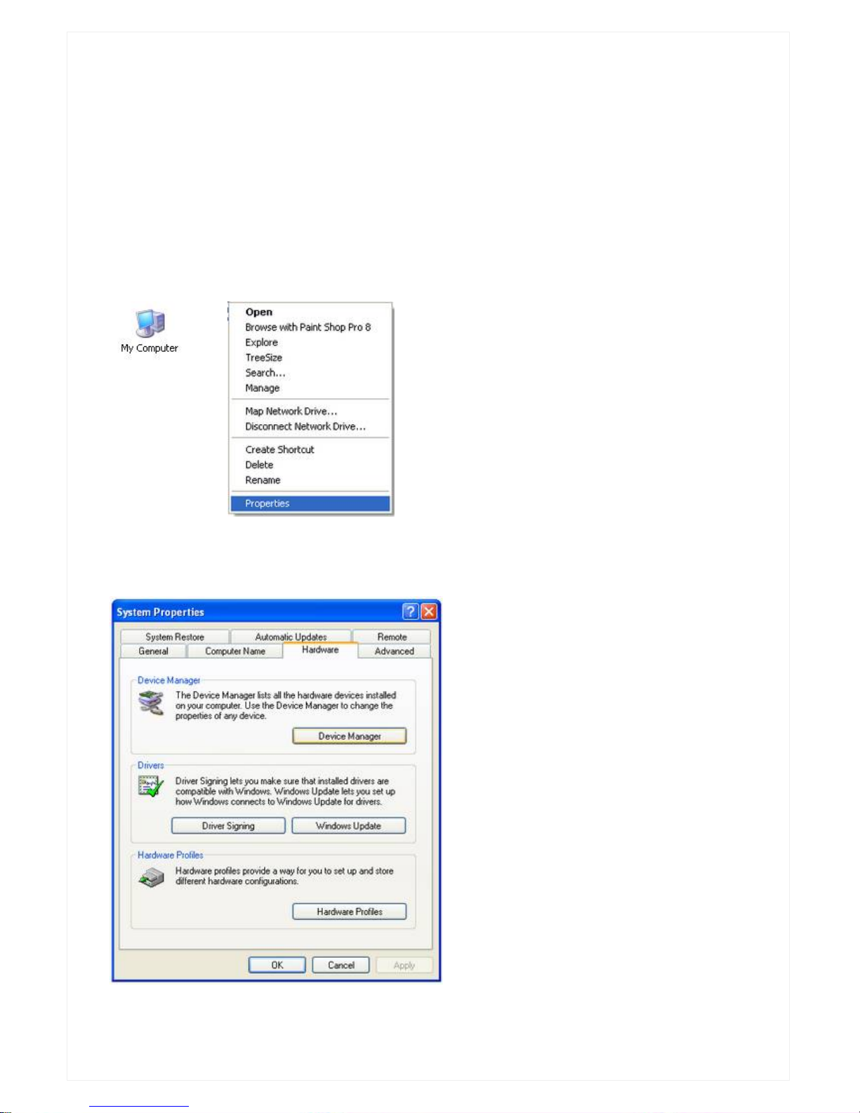
If you encounter any problems with the installation you may need to uninstall
the Micrometrics software and the camera drivers. You can un-install the
Micrometrics software via the Windows Add/Remove and the camera drivers
via the Windows Device Manager.
To remove the drivers successfully please follow the procedure below.
Right click on My Computer, then click
on Properties.
Click on Hardware, then click on
Device Manager.
Page 9
8
122CU
316CU
318CU
516CU
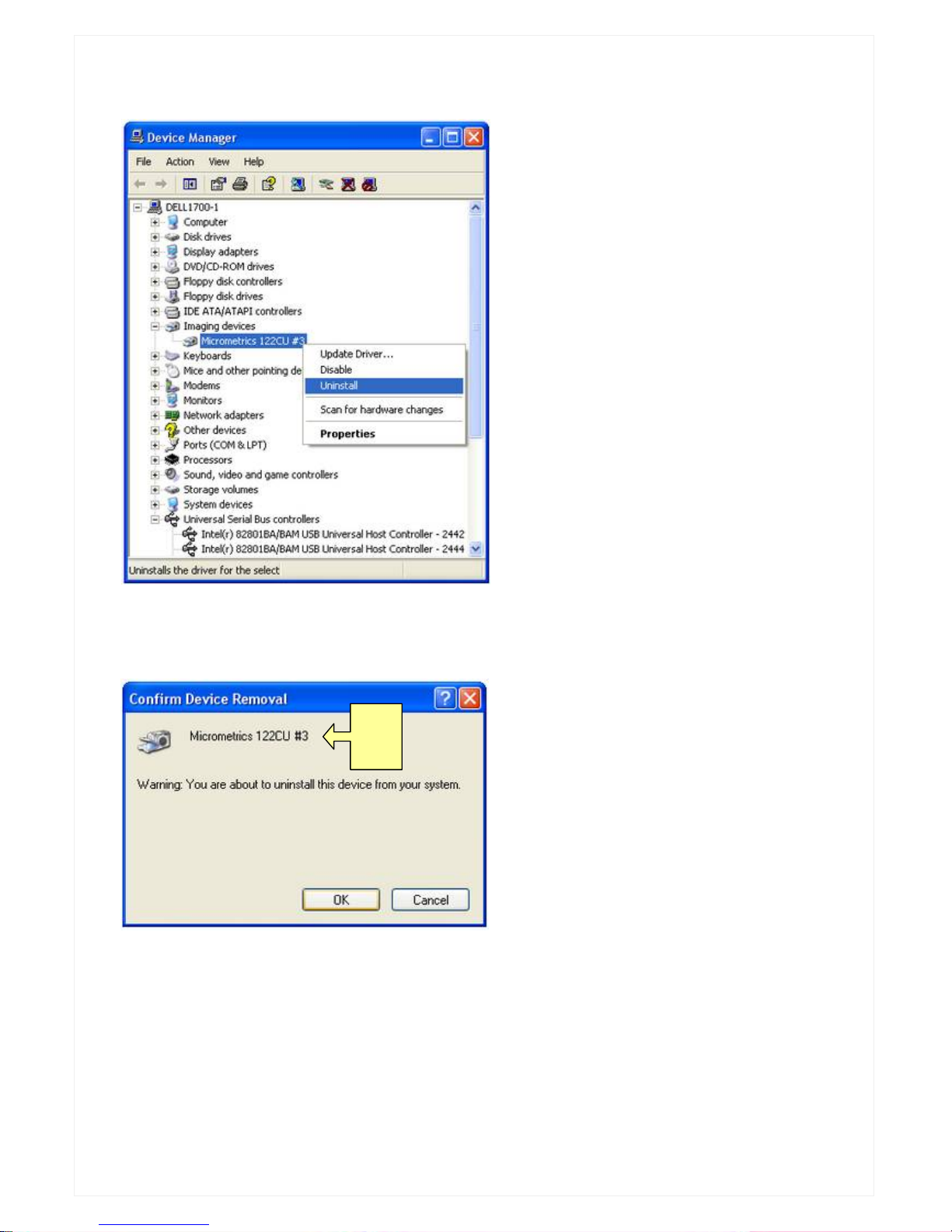
Click on Imaging devices, then
click on the Micrometrics entry.
Click on Uninstall to uninstall the
drivers.
Camera Driver Options
1. 122CU
2. 318CU
3. 518CU
NOTE: In some cases the Micrometrics entry may appear under Universal
USB controllers.
Click on OK to complete the drivers
removal process.
Once this has been done please switch off your PC for a few minutes before
trying installing the software and camera drivers again.
NOTE: You may need to uninstall and re-install the drivers if you use a
different USB port.
Page 10

9
Camera Performance
The camera is capable of very high update rates when taking into account the
high resolutions the cameras are capable of.
Performance will also greatly depend on the PC that the camera is connected
to.
For example typical performance on a 3.0GHz PC will be 12-14 frames per
second at 1280 x 1024 (1.3 mp). The image sent to the PC by the camera is
at high resolution, non-interlaced and uncompressed. This guarantees
images of the highest quality possible.
The frame rate will increase if you use a computer with a faster processor or
with a faster disk subsystem.
To increase performance on slower computers you may need to disable any
anti-virus, spyware and adware software as these may affect the performance
of your camera to a degree.
Decreasing the resolution where possible will also increase frame rates.
The performance of your camera will also depend on the bandwidth of the
USB bus. Typically maximum transfer for the three different types are:
PCMCIA/2 card (varies)
USB-PCI type card is 250Mbps (typical)
USB2.0 is 480Mbps (USB on motherboard)
So if you decide to get a PC at some point you would need to make certain
that the USB subsystem was already on the motherboard as this would offer
the maximum bandwidth possible for your system.
Page 11

10
Micrometrics BE: CMOS Cameras Edition
Micrometrics BE is a simple image capture application for use with CMOS
318CU-T and 518CU-T cameras.
User Interface
The application consists of two top-level windows, one is the video preview
window, the other is the control panel where camera control and image
acquisition commands are issued and options are set.
The control panel is further divided into two panes: imaging control pane and
camera control pane. To navigate to another pane, click the arrows or the
home icon at the top of control panel. The imaging control has four subpanes: operations, video mode, time lapse and clock. The camera control has
only one sub-pane, namely standard. The sub-panes are collapsible. To
collapse a sub-pane, click the up-pointing arrow at the sub-pane’s top right
corner. To expand a sub-pane that has collapsed to a title bar, click the downpointing arrow at the right end of sub-pane’s title bar.
The control panel can be docked to either the left side or the right side of the
desktop, or floating anywhere on the desktop. It can also take on different
looks, for example, that of Windows XP. The style may be user-customised.
The control panel can be made to auto-hide, meaning that it shrinks to a thick
column when mouse is not hovering at the side of desktop where the control
panel is docked. To configure the appearance of the control panel, right-click
the Micrometrics BE icon at the right end of the task bar, and in the popup
menu choose the “Settings” item.
To exit Micrometrics BE, choose the “Exit” item in the same menu. The other
two items in this popup menu is “Help”, i.e. to show this document, and
“About Micrometrics BE”, which provides copyright and version information
about this program.
Commands and Options - Camera Control
Preset
Micrometrics BE maintains a list of presets. A preset has a name associated
with it, and stores a camera’s control parameters. To create a preset for a
camera at a particular state, push the “Add” button. You will be prompted to
Page 12

11
enter a name to identify this preset. The current camera control parameters,
such as exposure time, gains and so on, will be stored into the preset under
the name you have specified. After a preset has been created, it can be
recalled at any time by choosing its name in the preset list box. The camera is
immediately restored to the state when that preset was created. To remove a
preset, first choose it from the list box, and then push the “Remove” button.
Flip
Check “Horizontal” to flip images horizontally. Check “Vertical” to flip images
vertically.
Flatfield Correction
Flatfield Correction refers to the cameras’ capability to compensate for
uneven illumination, non-uniform transmission rate of the lens, or spatially
varying response of sensor to incident rays. To build calibration base, push
“Make” button. To enable real-time Flatfield Correction, check “Use”.
This is an advanced function. To ensure optimal effects, follow the steps
below:
1. Shoot the camera at a slowly varying white background. The field of
view should not be obstructed by any object other than the white
background.
2. Adjust the illumination, objective lens aperture so that the image is as
bright as possible but not exceeding its dynamic range.
3. Perform white balance to remove the apparent color aberrations.
Frequency
To avoid possible flickers in the light source such as fluorescent lamps, check
“60Hz” where your AC power is 60Hz, check “50Hz” where you AC power is
50Hz. When there is no flicker in the light source, check “Other”.
Exposure
Use the slider to adjust exposure time. Note that the exposure range may
change with resolution setting. The allowed minimal and maximal exposure
time are shown below the slider at the left and right side. The current
exposure time is shown in the middle. Exposure time is in milliseconds.
Gain
Use the slider to adjust the gain of the camera. The allowed minimal and
maximal gain values are shown below the slider at the left and right side. The
current gain value is shown in the middle.
Page 13

12
White Balance
The two sliders here are for manual white balance. The usage is the same as
that of gain explained above.
Area WB
Click the button and then click a pixel of the live image. Micrometrics BE will
automatically calculate the necessary red and blue gains for correct color
reproduction. The calculation is based on a small neighborhood of the clicked
pixel. Hence you should have clicked somewhere that should be colorless but
instead is showing a tint.
Continuous AE
Check for continuous auto exposure.
Commands and Options - Imaging Control
Capture
Click to capture an image. The image will be placed on to clipboard in the
Windows DIB format. If a path has been properly specified, the captured
image will also be stored onto disk and open immediately for viewing with
Micrometrics Browser, a companion program of Micrometrics BE.
Path
Click to specify (part of) file names for images to capture. This will bring up
the standard File Save As dialog. The path information will be kept. The file
name, however, will only be used as the lead text of the files names of
images to capture. The trailing part of file names are automatically generated
by the software. The image format is Windows Bitmap.
Toggle View
The live image can be displayed as 1:1 or zoomed to window. In 1:1 mode
the scroll bars will be activated to facilitate viewing different parts of the
image. In zoomed mode, the live image is resized to fit to the preview
window. In this case, the full field of view is visible, and scroll bars are hidden.
To switch between the display modes, click this button.
Video Mode
Select the desirable resolution of the live image.
Page 14

13
Time Lapse
Time Lapse refers to capture of a sequence of images at regular time interval
during a certain period of time. Specify the interval length in the “Interval” and
the total duration in the “Duration” text box respectively. Both are in seconds.
Push the “Start” button to begin the time lapse capture, push the “Abort”
button to give up the initiated time lapse capture operation.
Clock
Prolonged work is hazardous to your health.
Page 15

14
Page 16

15
Opticstar Ltd,
87 Washway Road, Sale, Greater Manchester, M33 7TQ, United Kingdom.
Tel: +44(0)161 969 9008 - Web: www.opticstar.com - Email: [email protected]
OPTICSTAR
 Loading...