

Optics11 Piuma Nanoindenter, OP1550, CHIARO NANOINDENTER User Manual
PIUMA NANOINDENTER
USER MANUAL
2 optics11.com
CONTACT INFORMATION
Optics11
+31 20 598 7917
info@optics11.com
www.optics11.com
VISITING ADRESS
Optics11
VU University Campus
W&N Building room O-236
De Boelelaan 1081
1081 HV Amsterdam
The Netherlands
SHIPPING ADRESS
Optics11
De Boelelaan 1081
1081 HV Amsterdam
The Netherlands
COMPANY INFORMATION
Optics11 B.V.
KvK/CC: 52469417
VAT: NL850459734B01
Amsterdam, NL
Please see our website
for more information
about our products.
www.optics11.com

3
CONTENTS
Revision history 4
Safety 5
Introduction 6
1. Installation 7
2. Preparing the setup for measurement 10
3. Using the Piuma Nanoindenter 22
4. Optimizing instrument stability and sample
mounting 33
5. Working principle of the Piuma Nanoindenter
instrument 38
6. Description of the Piuma software 44
7. The OP1550 interferometer 57
8. FAQ & troubleshoot 61

4 optics11.com
REVISION HISTORY
Version 2.0 New document December 6, 2016 Ernst Breel
Version 2.1 Update March 14, 2017 Jakob Pyszkowski
Version 2.2 Update March 21, 2017 Jakob Pyszkowski
Version 2.3 Update March 29, 2017 Jakob Pyszkowski
Version 2.4 Update May 16, 2017 Jakob Pyszkowski
Version 2.5 Update July 18, 2017 Jakob Pyszkowski
Version 2.6 Update June 20, 2018 Kevin Bielawski
Version 2.7 Update November 7, 2018 Jakob Pyszkowski
5
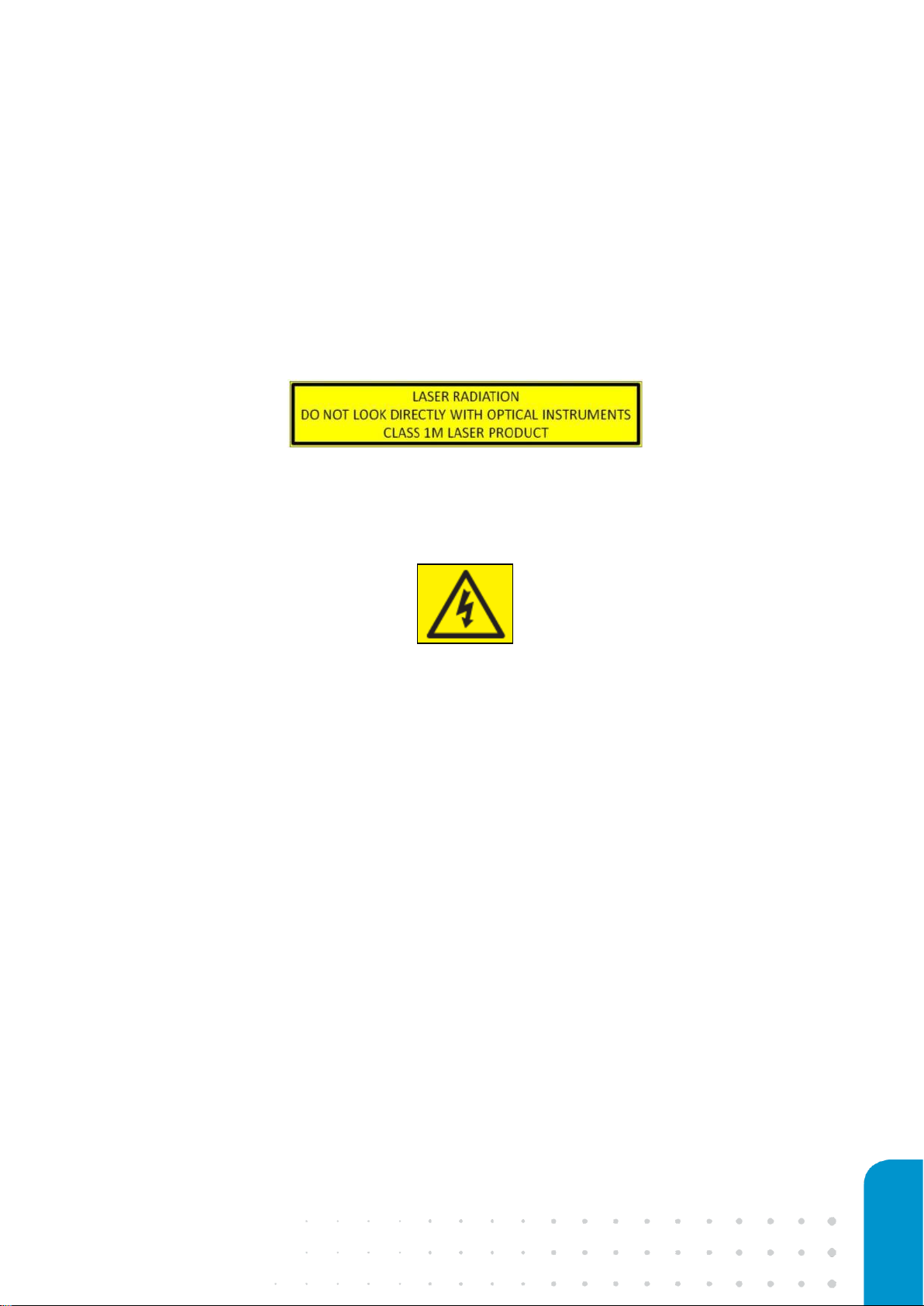
SAFETY
The OP1550 interferometer, part of the Piuma Nanoindenter, is equipped with a class 1M laser. The
laser light is coupled out via a fiber connector on the front panel and has a terminator on the back
panel. Do not view directly into the beam with optical instruments.
The OP1550 is equipped with a 220V/110V plug. Disconnect the instrument before changing the
fuse or before switching from 220V to 110V (or vice versa). Do not open the box, as this might result
in serious injuries.
6 optics11.com
INTRODUCTION
This document describes the installation and operation of the Piuma Nanoindenter instrument, as
developed by Optics11. Details of the installation of the Piuma Nanoindenter are provided in
Chapter 1. Chapter 2 describes the preparation of the Piuma Nanoindenter for experiments. How to
perform a measurement is described in detail in Chapter 3. Chapter 4 describes the optimization of
sample preparation and measurement conditions. Chapter 5 provides a description of the Piuma
Nanoindenter’s working principle. In Chapter 6 the Piuma Nanoindentation software suite is
explained in detail. Chapter 7 describes how to operate the OP1550 interferometer, and finally
Chapter 8 provides a FAQ and alternative options for support by a flowchart for troubleshooting.
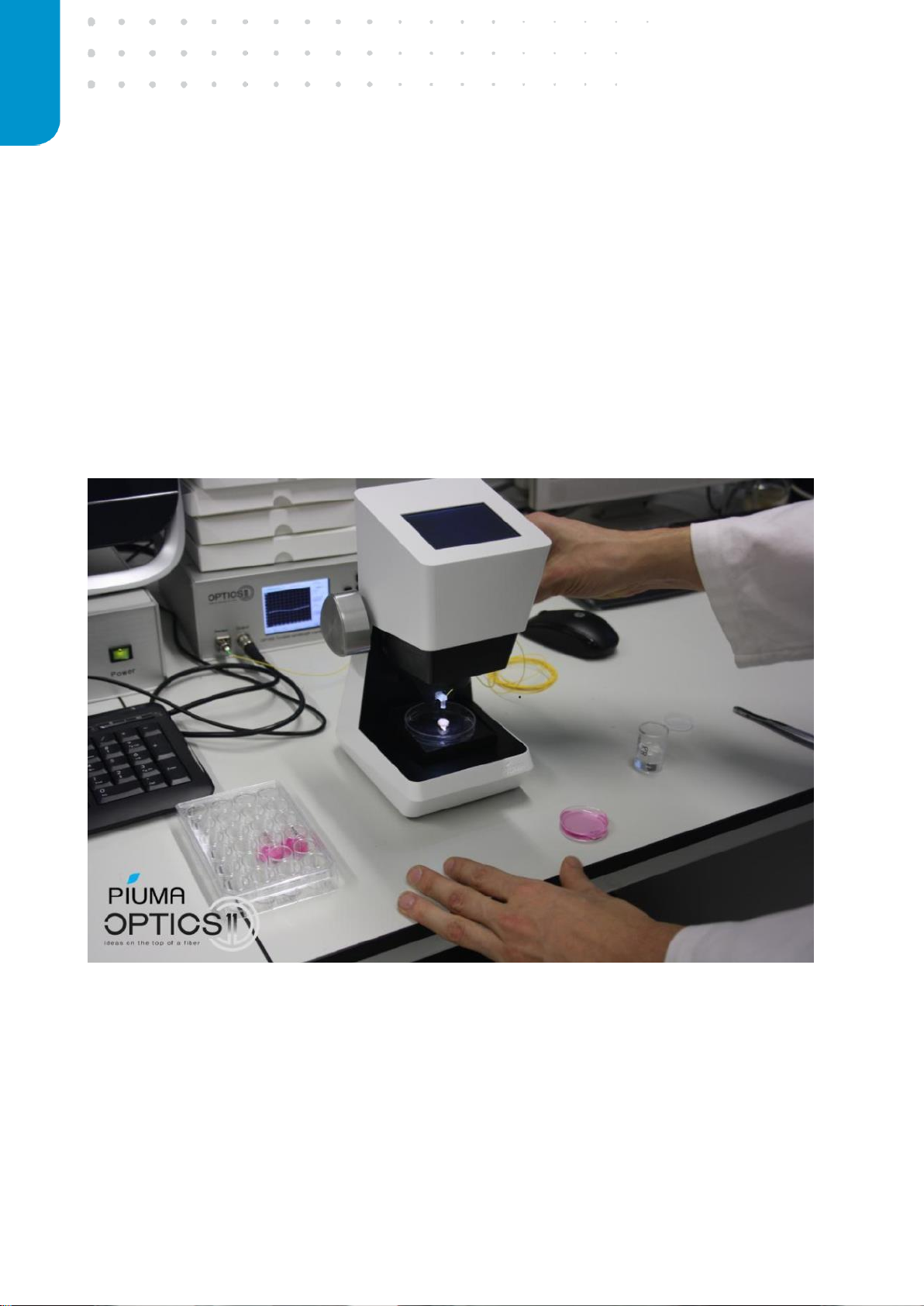
Figure 1: The Piuma Nanoindenter in action: measuring intact brain tissue.
7
1. INSTALLATION
This section describes the installation of the Piuma Nanoindenter by providing an overview of the
Piuma Nanoindenter and its components, the considerations for finding a location to set up the
system, the wiring scheme for connecting the individual components and the actions required to
start up the Piuma Nanoindenter.
1.1 The Piuma Nanoindenter and its components
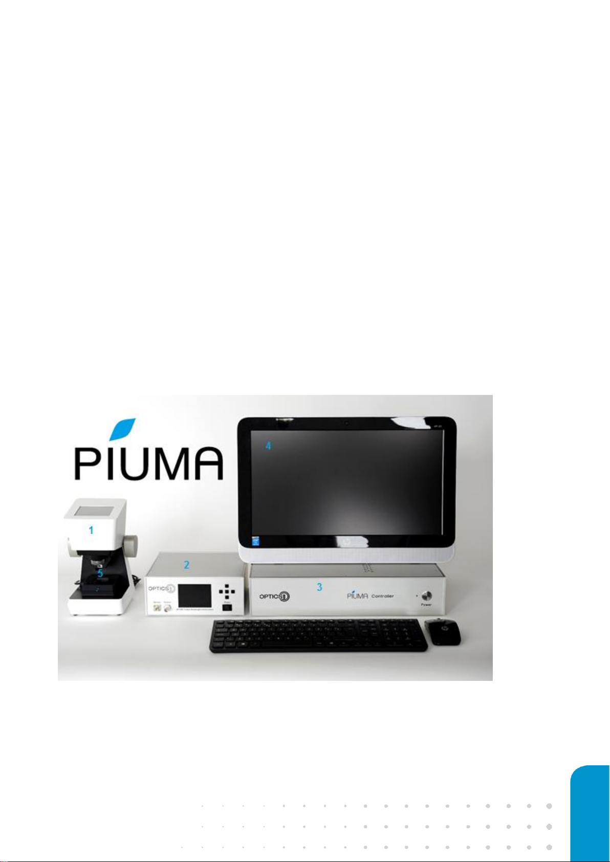
The Piuma Nanoindenter consists of five components: (1) The Piuma indenter head, (2) the Optics11
OP1550 interferometer, (3) the Piuma controller, (4) the PC running the Piuma Nanoindenter
software suite and (5) the Optics11 optical nanoindentation probes.
Figure 2: Picture of the Piuma Nanoindenter, showing the Piuma indenter head (far left), OP1550 interferometer, Piuma
controller and the PC.
8 optics11.com
The Optics11 OP1550 interferometer operates independently of the other components and can be
switched on and off at any time. The Piuma controller box powers the Piuma indenter head and
communicates with the software running on the PC and should not be switched off before exiting
the Piuma nanoindentation software suite. The software will automatically detect and connect to
Piuma components connected to the PC. For the best user experience, it is recommended to first
power on all peripheral components before running the software.
1.2 Connecting components
Together with the Piuma Nanoindenter the following cables are provided:
o 2x BNC connector cables
o 1x DVI signal cable
o 2x Power cable
o 1x PC power cable including adapter
o 2x USB (B-type) connector cable
o 50Ω Terminator
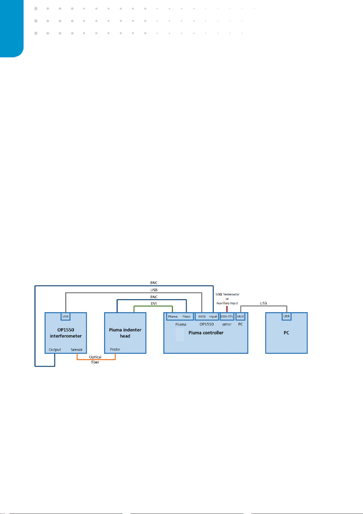
When installing the system, please carefully follow the scheme below (Figure 3).
Figure 3: Schematic drawing of the connections that are required to set-up the Piuma Nano-indenter.
The controller box is connected to the computer using one of the two USB ‘HUB’ connectors on the
back of the Piuma controller, and a free USB slot on the PC (must be a USB3.0 port). The Piuma
indenter head is connected to the controller box using the original DVI cable supplied with the
Piuma system, and a BNC cable connecting the BNC output on the indenters’ backpanel to the

9
‘Piezo’ input at the back of the controller. The OP1550 readout is connected to controller box using
one BNC and one USB cable. The BNC cable connects the ‘Output’ at the front of the OP1550 with
the ‘Input’ on the back of controller box and the second USB cable connects the ‘USB’ output on
the back of the OP1550 to the second ‘HUB’ connector on the back of the controller box (Figure 3).
The optional backlight module requires 5V to operate. To power this module, connect the USB
cable to any free USB port on the PC or the controller box.
The optional inverted camera module requires 5V to operate and can be connected to the Piuma
through a free USB HUB port at the rear of the controller box or directly to a free USB port on the
PC.

10 optics11.com
2. PREPARING THE SETUP FOR
MEASUREMENT
This section describes the steps required to start and prepare the system for a measurement series.
2.1 Starting the system
Powering up the system
Before starting up the setup for the first time, make sure that all cables are connected in the correct
way and the power switches on the back of the boxes are turned on. Switch on the devices in the
following order:
1. Computer
2. OP1550 interferometer
3. Controller box
The controller box automatically powers the Piuma Nanoindenter head and the LED illumination in
the indenter head will turn on. After initialization, the interferometer will show a live measurement
signal on the LCD screen.
Starting the software
Start the Piuma Nanoindenter program by double-clicking the Piuma software icon on the desktop.
The software is loading all devices while checking the hardware connection status, which should all
be ‘Idle’ (Figure 4). As a safety check, the program asks then to bring up the manual stage to the
upper most position. This prevents a collision of the probe with an obstacle while moving the
sample stage to the home position. To move the manual stage up, turn the grey knobs on the side
of the Piuma backwards until the stage reaches the top position. Next, press ‘OK’ in the software
dialog box to confirm nothing can obstruct the motion of the Piuma stages.
Figure 4: Hardware check.

11
This action initiates the homing of the X-Y stage of the Piuma Nanoindenter: The stage will move to
the front-left corner, set the current ‘X’ and ‘Y’ coordinates to ‘0’ and subsequently move to the last
coordinate set in the matrix scan parameters. After this, the system state will switch to ‘ready’, as
indicated in the status bar in the home screen.
2.2 Mounting a probe to the Piuma Nanoindenter
Selecting the right probe
Although a specific probe can measure a wide range of Young’s Moduli, selecting a probe with
suitable parameters that match with the specific sample properties can enhance the quality of the
measurement. For a softer sample, a probe with a less stiff cantilever is needed, and vice-versa, to
ensure that significant cantilever bending as well as significant sample indentation is achieved
during measurements. If the probe is either to stiff or too soft, there will be minimal cantilever
bending or indentation respectively, resulting in a less optimal signal-to-noise ratio.
Advised cantilever stiffness is provided for ranges of sample Young’s moduli in the table below:
Sample Young’s modulus
Advised cantilever stiffness range
10 Pa – 10 kPa
0.05 N/m
1 kPa – 500 kPa
0.5 N/m
500 kPa – 10 MPa
5 N/m
10 MPa – 100 MPa
50 N/m
100 MPa – 1 GPa
500 N/m
Table 1: Advised stiffness ranges for expected Young’s Moduli.
These are estimated for a tip radius of 50 µm, for smaller and larger tip sizes slightly softer and
stiffer cantilevers should be used, respectively. In case of doubt, please do not hesitate to contact
Optics11 for advice.
12 optics11.com
Installing a probe
After powering the Piuma Nanoindenter system and running the software, open the indentation
probe box. Carefully take first the probe out of the box in such a way that the probe can be clicked
in the Piuma indenter head in one go.
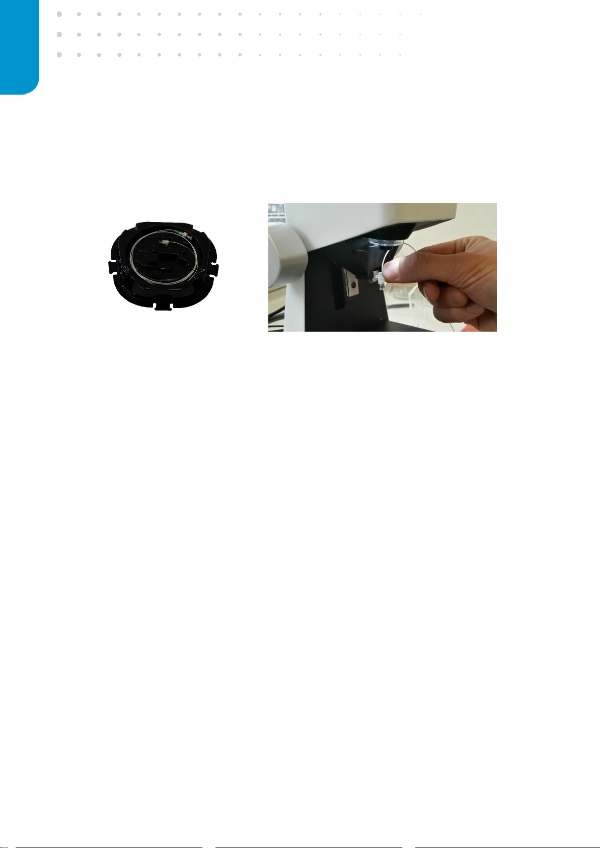
The probe is mounted in the Piuma indenter head by pushing the probe with the holder in the
probe mount (Figure 5). Make sure the cantilever points downwards and the probe is pushed all the
way to the most back-right position. When handling a probe, take special care to avoid any contact
with the cantilever as the glass cantilever at the end of the glass ferrule is extremely fragile and
almost any unintended contact will cause permanently damage. Therefore, when handling the
probe, always hold it by the plastic adapter, keep the optical fiber away from the cantilever and
avoid touching the glass part. Given the size of the probe, it is advised to hold the probe between
ones’ index finger and thumb whilst shielding it with the rest of the hand from the environment.
Figure 5: Probe and fiber wire inside the box (left), probe mounting to the indenter (right).
13
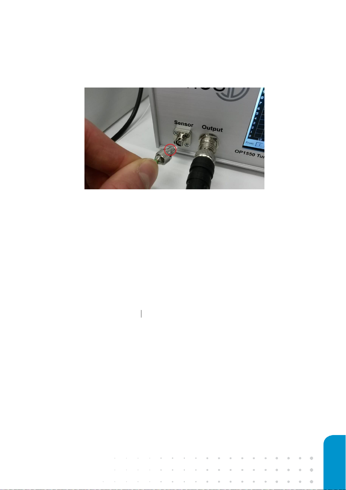
Next, remove the tape and green safety cap from the optical fiber connector and connect it to the
‘Sensor’ input of the OP1550 interferometer (Figure 6). The fiber connector is a FC/APC type
connector, which has a preferred orientation, indicated by the notch on the fiber connector and a
groove in the OP1550 connector. Please note the center terminus of the connector is very sensitive
to contamination or scratching – to avoid issues please use the green safety cap at all times when
storing the probe and avoid touching the terminus of the connector when the safety cap is off.
Caution: Avoid bending the optical fiber sharply: this can break the glass fiber.
If a previous probe is present in the Piuma, remove it before inserting the new probe. To avoid the
fiber from touching the probe when packing the fiber and optical connector, always place the fiber
first into the box and then the probe. For this, disconnect the optical connector from the OP1550,
bundle the fiber wire and put it into the box. Secure the optical connector in the box by placing a
piece of tape on top of the connector. You can remove then the probe from the Piuma indenter
head holder by compressing the plastic connector and pulling it gently out of the holder. Carefully
place the probe in the probe box to its designated location.
Caution: When installing the probe, always mount first the probe and then connect the fiber
to the OP1550. When putting the probe back into the box, always place and secure the fiber
wire first before placing the probe in the box.
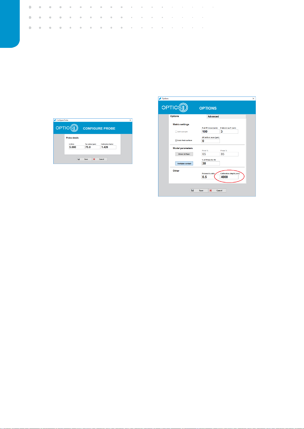
Configuring the probe in the software
It is important to correctly input the probe parameters in the software suite in order to obtain
meaningful measurement results. Probe parameters that need to be set in the program are the
cantilever spring constant (in N/m) and probe tip radius (in µm). These parameters can be entered in
the probe configuration menu, which can be accessed through the ‘Configure Probe’ item in the
main software window (Figure 7, left). The numbers can be found on the side of the probe
packaging box and are unique for each probe. If you accidently forget to update the probe details
Figure 6: Connecting the fiber to the OP1550, a notch (red circle) indicates the
preferred orientation
14 optics11.com
after changing the probe, you can still change those in the Dataviewer software while analyzing the
obtained data.
Figure 7: Configure probe menu (left), Options menus (right).
In most cases the probe must be calibrated first, which will result in a measurement of the factor
that describes the geometrical factor of the probe. As this is unique for each probe, leave the factor
1.000 in the configuration panel and see paragraph 2.4 “Calibrating the geometrical factor” in this
manual on how to obtain this value through the automated calibration procedure. For this
procedure a value of 4000nm for the calibration depth is set by default. You can can change this
value in the ‘Options’ menu, shown in the figure 7, right before peforming measurements with
higher indentation depths (<5000nm).
15
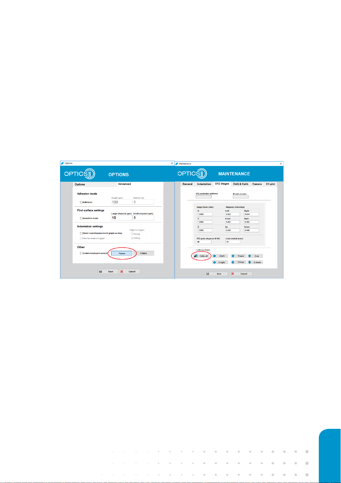
Setting the correct indenter head and corresponding XYZ stage values
The correct indenter head, here the Piuma, has to be selected in the ‘Advanced’ tab in the ‘Options’
menu (Figure 8, left). Since the XYZ stage travel values of the Piuma and Chiaro are differing, you
need to update the right values corresponding to the preferred indenter head. This can be
accomplished in the ‘XYZ stages’ tab of the maintenance menu by pressing ‘Calib. all’ (Figure 8,
right). You can enter this menu with the password ‘
showme
’ after clicking the ‘Maintenance’ button
in the main software window. This procedure will take a few minutes, since all XYZ values are being
calibrated.
Figure 8: Piuma selection in advanced options menu (left), XYZ stage calibration when switching between Piuma or Chiaro
Indenter head.

16 optics11.com
2.3 Calibrating the optical signal
For each unique medium/probe combination, the optical signal has to be calibrated. Once this is
done, the next step is to calibrate the geometrical factor (see paragraph 2.4).
Please note that for correct operation, the optical signal calibration should always be
performed before the geometrical factor calibration
The calibration of the optical signal is done by the OP1550 interferometer and controlled via by the
Piuma software. First ensure the optical probe is inserted in the Piuma indenter head and the
optical fiber connector is properly connected to the OP1550 interferometer ‘Signal’ input
connector. When preparing the probe to measure samples in a solution, please insert few
millimeters of solution in a clean petri-dish and use the manual stage to lower the probe into the
solution. Confirm the cantilever and a part of the glass probe is fully submersed and the liquid
tension cannot affect the cantilever anymore.
Please note that glass is hydrophobic, and that it is possible that an air bubble is trapped
between the cantilever and the glass base. This air bubble will affect the measurement, and
needs to be removed (see Chapter 4.3).
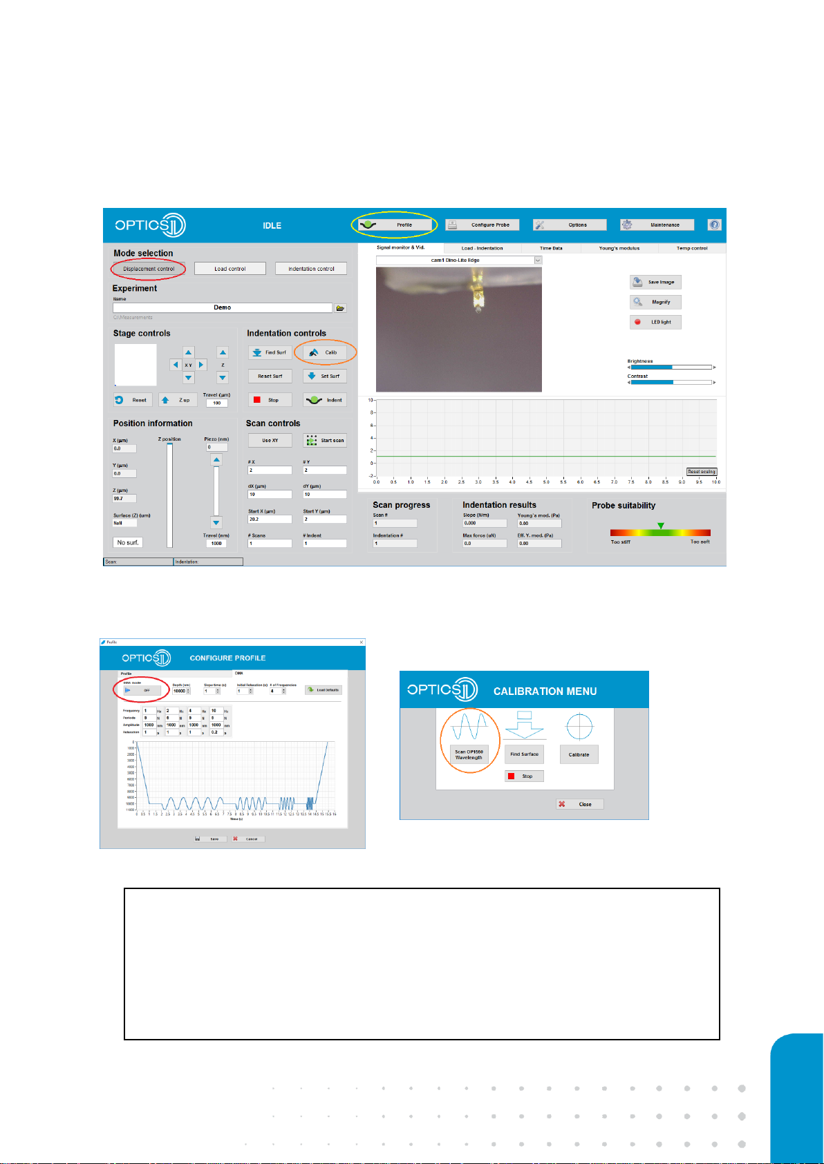
Automated optical signal calibration
Once the probe is connected and adapted to the correct medium, select the mode of operation in
main Piuma software window to ‘Displacement control’ (Figure 9) and be sure to turn off the DMA
mode in the DMA tab of the configure ‘Profile’ menu (Figure 10, left). Then click on ‘Calibration’ in
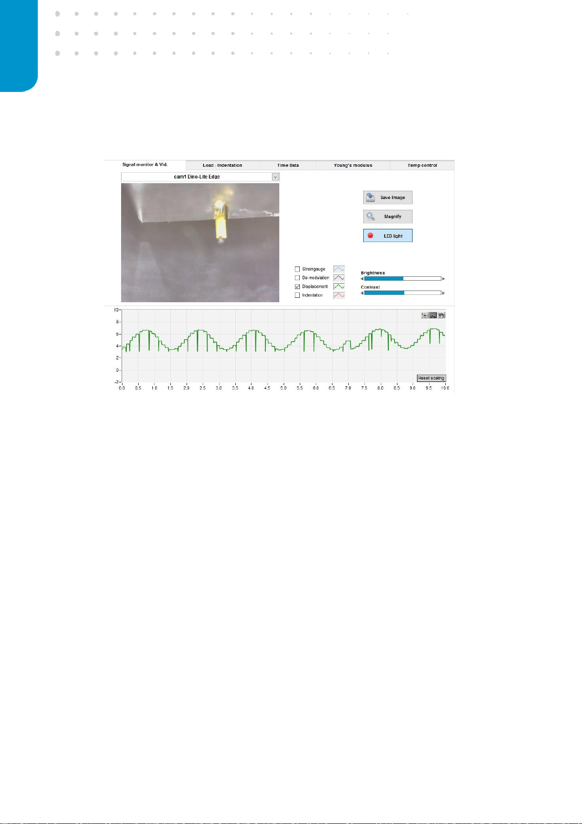
the Chiaro Software Menu to enter the calibration menu (Figure 9). Press ‘Scan OP1550 Wavelength’
to start the optical calibration (Figure 10, right). You can observe the wavelength scan process, after
closing the calibration window (Figure 11).
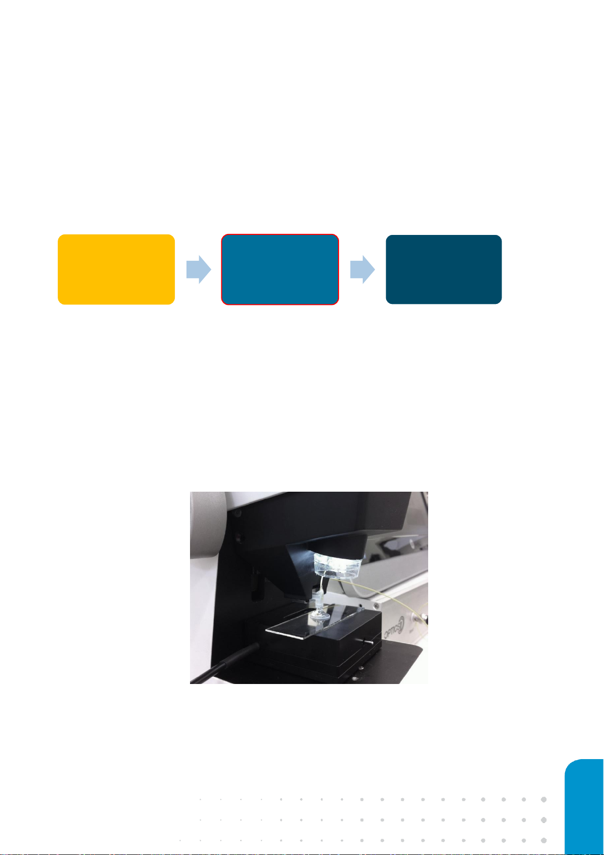
Optical
calibration
Geometrical
factor
Measurement
17
Figure 9: Set ‘Displacement control’ for automatic optical signal calibration.
Figure 10: DMA mode switch in profile configuration menu (left), ‘Scan OP1550 Wavelength’ for
automatic optical signal calibration (right).
Principle: The OP1550’s internal laser will tune its wavelength rapidly from ~1565nm to
~1525nm to create an interference pattern on the photodiode. As the photodiodes’
output voltage depends on the intensity of the interference pattern, an automated
offset and gain setting process is initiated, which optimizes the photodiode output for
the 0-10V range. The Piuma data acquisition system operates in the 0-10V range and
voltages outside this range cannot be collected.
18 optics11.com
Figure 11: Automatic optical signal calibration, displayed in the Piuma software.
This process must be performed for each new medium/probe combination: to measure multiple
samples in a solution of which the refractive index is not significantly different, this procedure does
not have to be executed again.
When performing experiments with temperature control, the calibration should be accomplished at
the same temperature as the measurement temperature. This is because the refractive index of the
medium is dependent on the temperature. Since the density of a liquid usually decreases with
temperature, it is not surprising that the speed of light in a liquid will normally increase as the
temperature increases. Thus, the index of refraction normally decreases as the temperature
increases for a liquid.
19
2.4 Calibrating the probe geometrical factor
After performing the optical calibration, the linearization of the interferometer and calibration of the
cantilever arm, also called geometrical factor, needs to be performed. Those two steps are
accomplished in one calibration procedure. During the signal linearization, the nonlinear response
due to cantilever bending is transformed to a linear signal, using the unity circle as a linearization
tool. The geometrical factor originates from the manufacturing process of the probes, which are
very specific components, and the distance between the tip position and the readout fiber position
can slightly differ from probe to probe. In the Piuma nanoindentation software, the automated
measurement and setting of the geometrical factor is included in the calibration procedure, also
referred to as ‘calibration factor’.
Make sure that the optical calibration was performed for the same medium/probe
combination for which you would like to perform the calibration of the geometrical factor!
e
Figure 12: Example of calibrating the probe in a droplet of medium on top of a regular microscope sample slide.
Optical
calibration
Geometrical
factor
Measurement
20 optics11.com
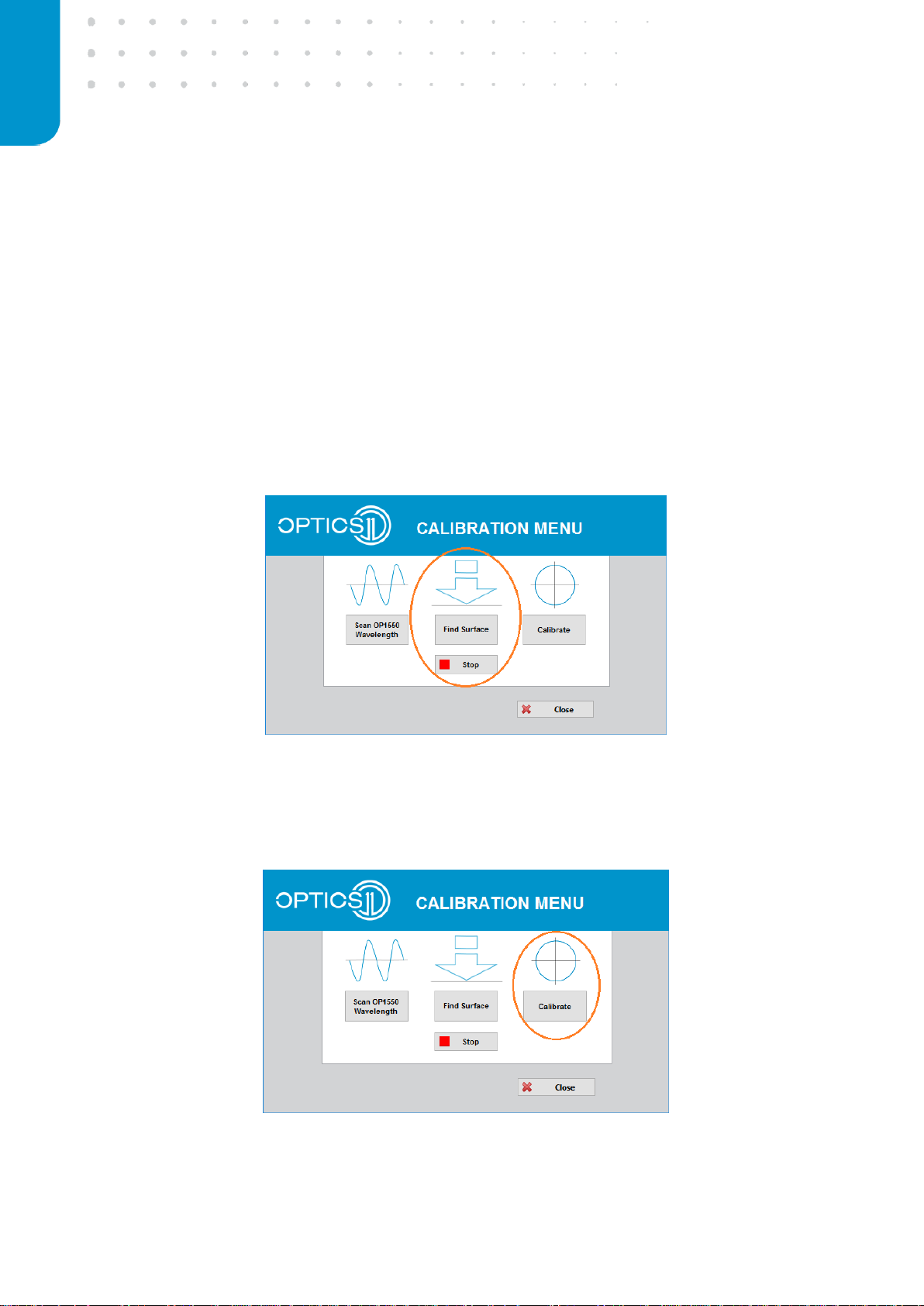
To linearize the interferometric signal and determine the calibration factor, the probe must be in
contact with a stiff surface, such as a glass slide or the bottom of a glass petri-dish, in an
environment that is comparable to the actual measurement environment. In case the measurement
takes place in a specific medium, please place the stiff calibration substrate inside a dish containing
the medium or place a large droplet of medium on top of the stiff substrate to allow full immersion
of the cantilever. In order to get into contact with the stiff surface, the Piuma Nanoindenter features
an automated find-surface approach. This approach uses a coarse-fine stepping routine, combining
the motorized Z stage and the indentation piezo. To initialize the automated find surface approach
for calibrating the geometrical factor, select the ‘Calibration’ tab in the Piuma software and click on
the ‘Find Surface’ button (Figure 13). For find-surface adjustments (e.g. when using very soft
cantilevers <0.4N/m), see Chapter 3.1 - ‘Using the automated find-surface function’.
Figure 13: Find surface to calibrate the geometrical factor.
Now that the probe is in contact, press the ‘Calibrate’ button in the calibration menu to initiate the
signal linearization and geometrical factor determination (Figure 14).
Figure 14: Calibration of the geometrical factor.
 Loading...