

Page 1
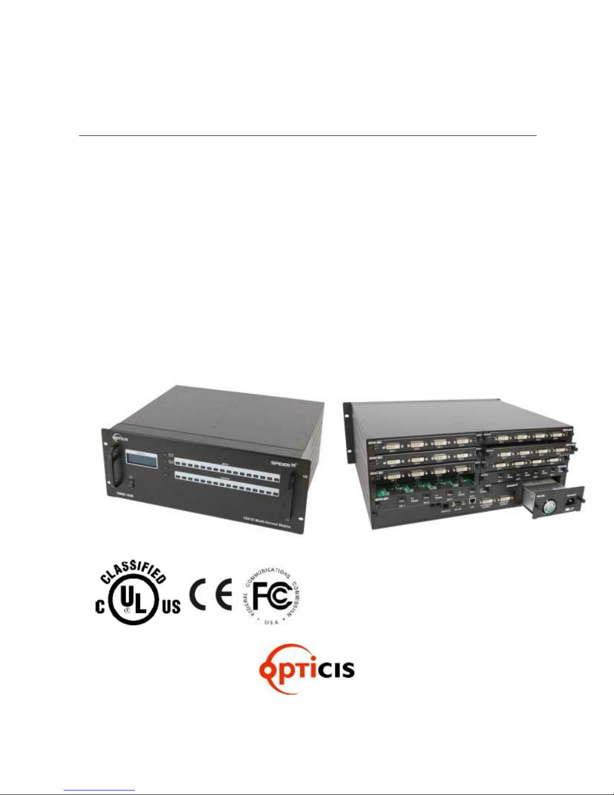
User’s Manual Version 1.5
OMM-1000
Multi-format matrix
16x16 DVI / HDMI / SDI / DisplayPort Matrix
Doc No. : OM-D150512 / Rev1.5
Page 2

2
TABLE OF CONTENTS
Chapter 1. Introduction and installation ................................................................................................ 4
1.1 Key features ............................................................................................................................ 4
1.2 Shipping group ........................................................................................................................ 5
1.3 Notice of safe usage ................................................................................................................ 5
1.4 Physical description ................................................................................................................. 6
1.5 Installation ............................................................................................................................... 7
1.5.1 Initialization ......................................................................................................................... 7
1.5.2 Connection for remote control ............................................................................................ 7
1.6 EDID Configuration .................................................................................................................. 7
Chapter 2. Control setup ....................................................................................................................... 9
2.1 TCP/IP ..................................................................................................................................... 9
2.1.1 TCP/IP setup of PC ............................................................................................................. 9
2.1.2 Launching Telnet ................................................................................................................ 9
2.2 RS-232 .................................................................................................................................. 10
2.2.1 Launching HyperTerminal ................................................................................................. 10
Chapter 3. Key button operation ......................................................................................................... 11
3.1 LINK mode ............................................................................................................................. 11
3.2 UNLINK mode ....................................................................................................................... 11
3.3 FUNCTION mode .................................................................................................................. 11
3.3.1 Gateway ............................................................................................................................ 12
3.3.2 Subnet Mask ..................................................................................................................... 12
3.3.3 IP Address ........................................................................................................................ 12
3.3.4 MAC Address .................................................................................................................... 13
3.3.5 UDP Port Number ............................................................................................................. 13
3.3.6 Multi Viewer ...................................................................................................................... 14
3.3.7 Video Generator ................................................................................................................ 14
3.3.8 Monitoring Output ............................................................................................................. 15
3.3.9 EDID Configure ................................................................................................................. 15
3.3.10 Baud Rate ......................................................................................................................... 16
3.3.11 Control Lock ...................................................................................................................... 17
3.3.12 Reset Mode ....................................................................................................................... 17
3.4 Preset mode ........................................................................................................................ 118
Chapter 4. PC program operation ....................................................................................................... 19
4.1 Basic setup ............................................................................................................................ 20
4.1.1 Connect Info ...................................................................................................................... 20
4.1.2 Channel Name .................................................................................................................. 21
4.1.3 Video Generator ................................................................................................................ 21
4.1.4 Control Lock Mode ............................................................................................................ 21
4.1.5 Network ............................................................................................................................. 21
4.2 EDID setup ............................................................................................................................ 21
4.3 Operation ............................................................................................................................... 22
4.3.1 Input / output connection................................................................................................... 23
4.3.2 Input channel status .......................................................................................................... 23
4.3.3 Output channel status ....................................................................................................... 24
4.3.4 Multi-viewer ....................................................................................................................... 24
Chapter 5. Web control panel operation ............................................................................................. 27
Page 3

3
Chapter 6. Command input operation................................................................................................. 28
6.1 Command input structure ...................................................................................................... 28
6.2 Examples of command inputs ............................................................................................... 29
6.2.1 Link input and output ......................................................................................................... 29
6.2.2 Input and output status ..................................................................................................... 29
6.2.3 Network setting ................................................................................................................. 30
6.2.4 Video generator setting ..................................................................................................... 30
6.2.5 Monitor output port setting ................................................................................................ 31
6.2.6 EDID control command ..................................................................................................... 32
6.2.7 Baud rate setting for RS-232 ............................................................................................ 32
6.2.8 Multi-viewer card (QDVI-O) setting ................................................................................... 33
6.2.9 Slot status request ............................................................................................................ 34
6.2.10 Control lock command ...................................................................................................... 35
6.2.11 Preset Control command .................................................................................................. 35
Chapter 7. Firmware update ............................................................................................................... 36
Chapter 8. Trouble shooting ............................................................................................................... 39
Chapter 9. Specification ...................................................................................................................... 40
9.1 General specification ............................................................................................................. 40
9.2 Power Specification ............................................................................................................... 41
9.3 SDI video input and output scaling condition ........................................................................ 41
9.4 Compatibility between Dual link DVI In/Output cards and other In/Output cards.........................42
9.5 Compatibility between DisplayPort In/Output cards and other In/Output cards...........................42
Chapter 10. Warranty Information ...................................................................................................... 43
Chapter 11. Safety Instructions .......................................................................................................... 44
Chapter 12. Maintenance ................................................................................................................... 46
Chapter 13. UL /EN Statement ........................................................................................................... 47
Chapter 14. Symbol Definitions .......................................................................................................... 48
Page 4

4
Chapter 1. Introduction and installation
Purpose
The modular matrix, OMM-1000 enables to connect between various video sources and displays and
it offers flexible installation with other video controllers or control software. The input and output cards
are composed of 4 ports, therefore user can easily configures any input and output channels from 4x4
to 16x16 by plugging the cards into OMM-1000 mainframe.
Introduction
The OMM-1000 modular matrix enables to switch up to 16 different DVI, HDMI, SDI, and DisplayPort
sources to 16 different digital displays. It can be configured using 4 input and output cards and each
card has 4 ports of input and output. In case of Dual link DVI card (DDVI-2EI / DDVI-2EO), it is
composed of 2 ports, therefore configuration for input and output channels are from 2x2 to 8x8.
Note) SDI is not a licensed HDCP interface and if the content received from HDMI is protected by
HDCP, there should be no output from the SDI slot.
1.1 Key features
▪ Up to 16 DVI, HDMI, SDI, and DisplayPort inputs and outputs can be configured.
▪ Each card has 4 input or 4 output ports and 4 cards can be fitted into input and output bays.
Dual link DVI supports from 2 x 2 to 8 x8 input and output.
▪ Has Electrical DVI, HDMI, SDI, DisplayPort and Optical DVI input and output cards.
▪ Complies with DDC/HDCP (Electrical DVI and HDMI cards only).
▪ Complies with DPCD (Electrical DisplayPort card only).
▪ Supports up to WUXGA (1920x1200) at 60Hz refresh ratio for Single link DVI, WQXGA
(2560x1600) at 60Hz refresh ratio for Dual link DVI and DisplayPort or 1080p at 60Hz for
HDMI and SDI.
▪ Supports 3 types of EDID management:
Default Mode.
Auto Mix Mode.
Output Copy Mode.
▪ Supports various control methods:
Key buttons operation
Command input (Such as Hyper terminal by RS-232 and Telnet by TCP/IP)
Web panel control (TCP/IP)
PC program by RS-232 and UDP
Page 5

5
▪ Works with OPTICIS DVI, HDMI, SDI, and DisplayPort optical extender for long signal
extension.
▪ Has dual-power supplier for hot-swappable and load-sharing.
▪ Equips multi-viewer card to be used in various monitoring systems.
▪ Provides Preset mode to save and load the routings status.
▪ Provides diagnostic function for quick trouble shooting.
▪ Has video generator output and monitoring output for easy installation.
1.2 Shipping group
▪ OMM-1000, Modular matrix chassis: 1 EA
▪ Input output cards: Option
SDVI-4EI, 4 ports electrical Single link DVI input card
SDVI-4EO, 4 ports electrical Single link DVI output card
DDVI-2EI, 2 ports electrical Dual link DVI input card
DDVI-2EO, 2 ports electrical Dual link DVI output card
SDVI-1FI, 4 ports 1 fiber optical DVI input card
SDVI-1FO, 4 ports 1 fiber optical DVI output card
HDMI-4EI, 4 ports electrical HDMI input card
HDMI-4EI, 4 ports electrical HDMI output card
SDI-4EI, 4 ports electrical SDI input card
SDI-4EO, 4 ports electrical SDI output card
DP1-4EI, 4 ports electrical DisplayPort input card
DP1-4EO, 4 ports electrical DisplayPort output card
QDVI-O, Multi-viewer card
▪ AC power cord: 1 EA
▪ Power supplier: 1 EA (Dual power supplier is an option)
▪ User manual: 1 EA
▪ Firmware download cable: 1 EA (Use only this accessory specified by the manufacturer)
▪ RS-232 cable (Straight type): 1 EA
▪ PC software CD: 1 EA
1.3 Notice of safe usage
We recommend you to read following warning, precaution and information before start to
operate the OMM-1000 modular matrix.
▪ Use of the equipment in a manner not specified by the manufacturer may result in ire-
coverable damage.
Page 6
6
▪ Keep the unit away from liquid, magnetic and combustible substances.
▪ Do not place heavy weight on the unit.
▪ Move away from noisy environment such as vibration or impact.
▪ Do not install the unit vertically. / Do not disassemble the unit.
▪ Carry the unit using the handle in front of the panel with two (2) Users.
1.4 Physical description
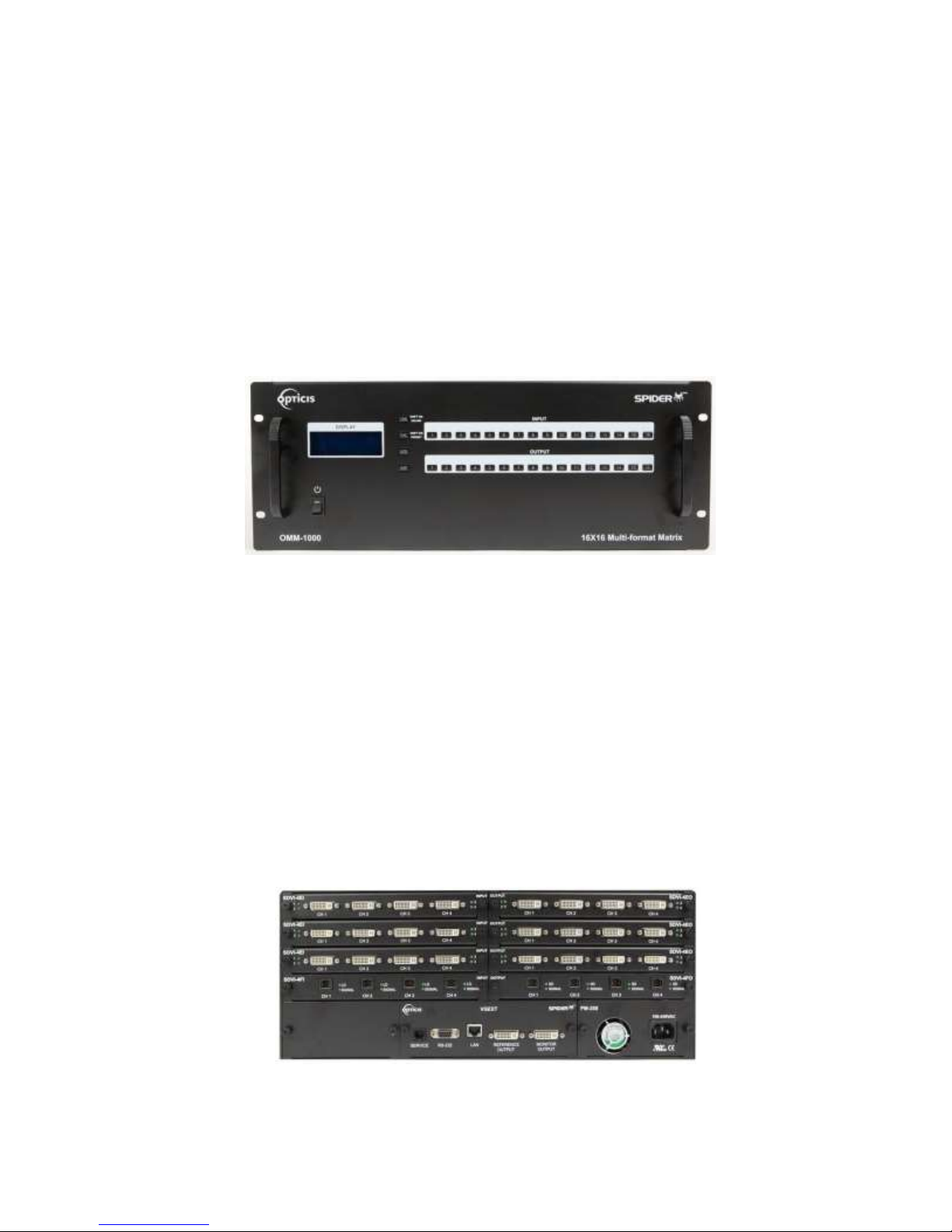
The OMM-1000 modular matrix chassis is mountable on a 19” standard rack. Key buttons,
LCD display and reset switch are placed on the front panel as shown in Figure 1-1.
All Input and output cards, interface ports and power supplier are placed on the rear panel as
below.
▪ Input bay for 4 input cards (left side)
Figure 1-1 Front panel of OMM-1000
▪ Output bay for 4 output cards (right side)
- Input and Out bay for 2 in/output cards (Only Dual link cards)
▪ SERVICE, RJ-11 receptacle for firmware upgrade
▪ RS-232, Serial communication port
▪ LAN, RJ-45 receptacle for TCP/IP or UDP control
▪ REFERENCE OUTPUT for internal video source for easy installation
▪ MONITORING OUTPUT for internal output port to monitor input signal
▪ Power supplier (Dual-power is an option)
Figure 1-2 Rear panel of OMM-1000
Page 7

7
1.5 Installation
1.5.1 Initialization
▪ Put insert the cards into each input or output bay according to user interface.
▪ All input or output cards have the same connection way, and tighten the screws just until
snug against the main frame. Then, please make sure the cards are fully seated.
▪ Connect the provided AC power cord to AC power inlet and turn on switch on the front
panel. Then, OMM-1000 will start initialization process (To turn it off completely, pull out
AC power cord, switch on the front panel is reset switch).
▪ ‘OMM-1000 Starting’ will be shown on LCD display.
▪ After 7~10 sec, ‘OMM-1000 Booting complete’ message and hardware and firmware
version information will be shown.
▪ Now, OMM-1000 is ready to receive commands from user.
1.5.2 Connection for remote control
▪ Connect the OMM-1000 to PC with the supplied RS-232 cable.
▪ Connect the OMM-1000 to PC with LAN cable with RJ-45 connector.
[NOTE] Typically, the IP address of PC connected to the network is configured by DHCP
server. But, if the PC is connected directly to the OMM-1000, the network server will
not able to assign the IP address. In this case, network information of PC should be
set manually.
The default IP address of OMM-1000 is 192.168.1.117. Before connecting OMM1000 to your network, please verify the availability of IP address in your network.
The IP address can be reconfigured by key button, PC program or command lines
over RS-232 or TCP/IP.
1.6 EDID Configuration
▪ EDID (Extended Display Identification Data) is an information set that is provided by a
display to describe its capabilities to a graphic source. It enables a graphic source to identify
the connected display.
▪ The information set includes: manufacturer, product type, phosphor or filter type, timings
supported by the display, display size, luminance data and (for digital displays only) pixel
mapping data.
▪ Once the graphic source reads the information set (usually during the booting process), the
EDID determines the optimal format for a connected display.
Page 8
8
EEPROM1
EEPROM2
EEPROM3
EEPROM16
EDID
INTERFACE
CONTROL
Read/Write
Sources
INPUT 1~16
Displays
OUTPUT 1~16
WRITE EDID
.
.
.
.
.
.
.
.
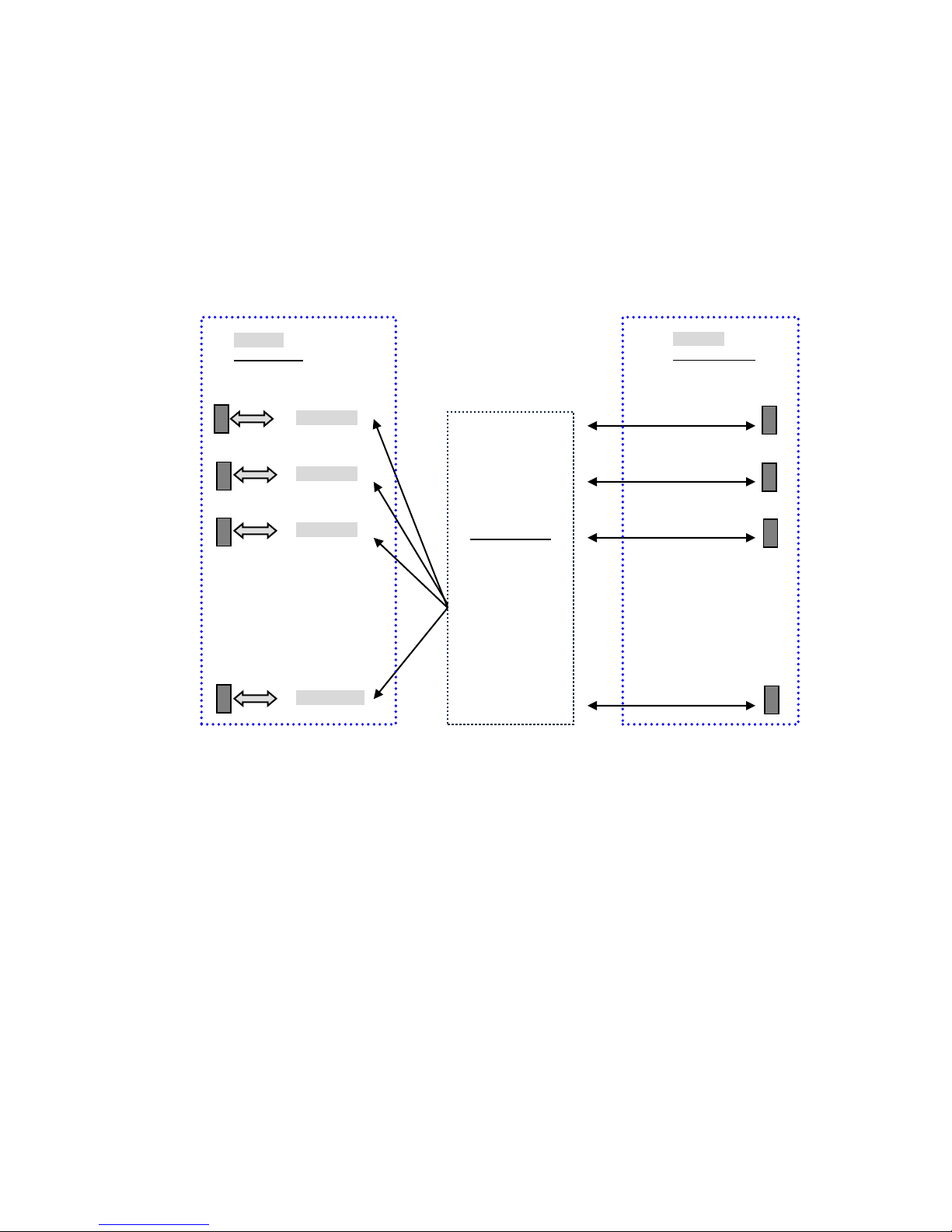
▪ OMM1000 supports storing of EDID information to an EEPROM for each Input.
▪ OMM1000 has three-way EDID settings, 1) Default Mode: default EDID from the factory, 2)
Output Copy Mode: read of EDID from any target display and copy in input port and the most
advanced one is 3) Auto Mix Mode: analyzing of all EDID from the attached displays and
store optimized EDID in input port to avoid any compliance problems in the field.
Figure 1-3 Concept of EDID setting and working in OMM-1000 modular matrix
As depicted in Figure 1-3, once EDID is configured, each EDID is stored in EEPROM in Input
ports. As a result, the video sources are able to read EDID from the EEPROM during booting
process even though the OMM-1000 and connected displays are not powered on yet.
Page 9

9
Chapter 2. Control setup
The OMM-1000 modular matrix can be controlled in various ways such as command input (RS-232,
TCP/IP), Web control panel (TCP/IP), supplied PC program (RS-232, UDP) as well as key button on
the front panel. To do this, PC should be configured properly.
2.1 TCP/IP
2.1.1 TCP/IP setup of PC
TCP/IP, the abbreviation of Transmission Control Protocol (TCP) and the Internet Protocol (IP)
is commonly used protocol to control remote computers.
To control OMM-1000 over TCP/IP, set network properties of PC as below (Explained here is
based on Win 7 OS).
▪ Open Control Panel.
▪ Select Network Status in Network and Internet menu.
▪ Select Adapter setting.
▪ Select Local Area Connection and right click to open property.
▪ Select Internet Protocol Version 4 (TCP/IPv4)
▪ Enter IP, Subnet mask, Gateway and DNS server address, compatible with the current
network setting of OMM-1000.
▪ Click OK to terminate IP setup session.
[Note] If the IP address of OMM-1000 is 192.168.001.117, the PC IP address should be
chosen as 192.168.001.nnn; where ‘nnn’ can range from 000 to 255 except 117.
2.1.2 Launching Telnet
Telnet is a terminal program embedded in Window OS system to access remote computers
using TCP/IP protocol. With the network setting of the PC as above, launch Telnet as below.
▪ Make sure PC and OMM-1000 are connected by Ethernet.
▪ Click Start menu and select Run.
▪ Type CMD to open command window.
▪ Type ‘telnet 192.168.1.117’ (Type current IP address of OMM-1000).
▪ Press ENTER then, “==Welcome to OMM-1000==” and “== TELNET control ==”
messages will be shown.
Page 10

10
▪ Type command inputs to control OMM-1000. (Refer to Chap. 5)
2.2 RS-232
2.2.1 Launching HyperTerminal
The OMM-1000 modular matrix provides RS-232 serial communication. The simplest way to
control OMM-1000 over RS-232 is using embedded software in Windows OS, HyperTerminal.
To launch Hyper Terminal (Explained here is based on Windows XP OS. Hyper Terminal is
not available on Win 7.):
▪ Connect the PC to OMM-1000 over RS-232 cable.
▪ Select Start > Programs > Accessories > Communications > HyperTerminal.
▪ Enter a name and choose an icon in Connection Description window and click OK.
▪ In Connect To window, ignore the Country, Area Code and Phone Number fields but select
available COM port of PC to be connected to OMM-1000 then, click OK.
▪ In COM Properties window, set the parameters as below:
Bits per second (baud rate): 115200 (115200 is default baud rate of OMM-1000)
Data bits: 8
Parity: None
Stop bits: 1
Flow control: None
[Note] Bit per second of Hyper Terminal should be set as same as baud rate of OMM-1000.
▪ Click OK to save the parameters.
▪ Go Start > Programs > Accessories > Communications > HyperTerminal, then new icon
will be shown. Then select it to launch Hyper Terminal.
▪ Type command inputs to control OMM-1000 (Refer to Chap. 5)
Page 11

11
Chapter 3. Key button operation
3.1 LINK mode
▪ It configures input / output connections for cross-switching.
1) Press LINK key button.
2) Press an input key button - LCD will display current connected output.
3) Press single or multiple output key buttons to select desired outputs.
4) Outputs can be deselected by pressing the each output key button again.
5) Press ENTER key button to save the configuration.
6) To configure next Input / output connection, repeat steps 1 to 5.
3.2 UNLINK mode
▪ It unlinks input /output connection.
1) Press SHIFT key button.
2) Press LINK key button.
3) Press the input key button to be disconnected.
4) Press ENTER key button.
3.3 FUNCTION mode
▪ It configures basic setting of OMM-1000 to be controlled by command input and PC program.
▪ Press FUNCTION to see features – FUNCTION key button will cycle the following features
repeatedly:
Gateway
Subnet Mask
IP Address
Mac Address
UDP Port Number
Multi-viewer (It is activated when QDVI-O is in output bay)
Video Generator
Monitoring Output
EDID Configure
Baud Rate
Control Lock
Reset Mode
Page 12

12
3.3.1 Gateway: Press FUNCTION key button once
▪ The cursor shows that it is selected and activated.
▪ Input 3 key button decreases the number.
▪ Input 4 key button increases the number.
▪ Input 1 and 2 key buttons move the cursor left and right.
======Gate Way======
O: 192. 168. 001. 001
N: 192. 168. 001. 001
▪ Modify the Gate way address to be used for your network.
▪ Press ENTER key button to complete the process.
▪ The default setting is 192.168.001,001
3.3.2 Subnet Mask: Press FUNCTION key button two times
▪ The cursor shows that it is selected and activated.
▪ Input 3 key button decreases the number.
▪ Input 4 key button increases the number.
▪ Input 1 and 2 key buttons move the cursor left and right.
====Subnet Mask====
O: 255. 255. 255. 000
N: 255. 255. 255. 000
▪ Modify the Subnet mask address to be used for your network.
▪ Press ENTER key button to complete the process.
▪ The default setting is 255.255.255.000.
3.3.3 IP Address: Press FUNCTION key button three times
▪ The cursor shows that it is selected and activated.
▪ Input 3 key button decreases the number.
▪ Input 4 key button increases the number.
▪ Input 1 and 2 key buttons move the cursor left and right.
=====IP Address=====
O: 192. 168. 001. 117
N: 192. 168. 001. 117
Page 13

13
▪ Modify the IP address to be used for your network.
▪ Press ENTER key button to complete the process.
▪ The default setting is 192.168.001.117.
3.3.4 MAC Address: Press FUNCTION key button four times
▪ The cursor shows that it is selected and activated.
▪ Input 3 key button decreases the number.
▪ Input 4 key button increases the number.
▪ Input 1 and 2 key buttons move the cursor left and right.
=====MAC Address====
O: 00.11.AA.EE.DD.FF
N: 00.11.AA.EE.DD.FF
▪ Modify the MAC address to be used for your network.
▪ Press ENTER key button to complete the process.
3.3.5 UDP Port Number: Press FUNCTION key button five times
▪ It makes number setting, data range from 0 to 65535.
▪ The cursor shows that it is selected and activated.
▪ Input 3 key button decreases the number.
▪ Input 4 key button increases the number.
▪ Input 1 and 2 key buttons move the cursor left and right.
=========Function Mode========
Port Number
Old data: 03000
New data: 03000
▪ Modify the UDP port number to be used for your network.
▪ Press ENTER key button to complete the process.
▪ The default UDP port number is 03000.
[Note] Port number setting in this section is used for UDP with supplied PC program not
TCP/IP with web browser or Telnet. For TCP/IP, port number 23 is fixed value.
Page 14

14
3.3.6 Multi Viewer: Press FUNCTION key button six times
▪ Multi-viewer card, QDVI-O can choose 4 inputs among 16 inputs of OMM-1000 and
configure and output these input signals with 7 different layouts. For more details, refer to
chap. 4.3.4.
▪ The cursor shows that it is selected and activated.
▪ Input 1 and 2 key buttons move the menu.
▪ Input 3 key button decreases the number.
▪ Input 4 key button increases the number.
====Multi Viewer====
SLOT No.: 01
Resol: 01 800x600
Layer: Layer 01
1) Select the SLOT No. by pressing input 3 or 4 key button. It shows location where the
QDVI-O is inserted among output slots. If only one QDVI-O is inserted the number will
be fixed and not changed.
2) Select the output resolution.
3) Select Layout.
4) Press ENTER key button to complete the process.
3.3.7 Video Generator: Press FUNCTION key button seven times
▪ It changes resolution and pattern of video generator.
▪ The cursor shows that it is selected and activated.
▪ Input 1 and 2 key buttons move the menu.
▪ Input 3 key button decreases the number.
▪ Input 4 key button increases the number.
==Video Generator==
Resol: 01 800x600
Image: 01 V Bar Stop
OSD: ON
1) Select the resolution, pattern and OSD by pressing the key buttons as guided above.
2) Press ENTER key button to complete the process.
[Note] OSD shows the resolution and pattern information on the top left of the display.
Page 15

15
3.3.8 Monitoring Output: Press FUNCTION key button eight times
▪ It allocates input to Monitor Output port for monitoring uses.
▪ The cursor shows that it is selected and activated.
▪ Input 3 key button decreases the number.
▪ Input 4 key button increases the number.
=Monitoring Output=
Old Input: 01
New Input: 01
1) Connect a display to the Monitoring Output port and any video sources to the DVI input
ports on the real panel.
2) Select an input port by pressing input 3 or 4 key button.
3) Press ENTER key button to complete the process.
3.3.9 EDID Configure: Press FUNCTION key button nine times
▪ It sets EDID information in input port.
▪ OMM-1000 supports three types of EDID setting: Default Mode, Auto Mix Mode and Output
Copy Mode. For more information, refer to Chap. 5.2.
▪ The cursor shows that it is selected and activated.
▪ Input 1 and 2 key buttons select YES and NO.
▪ Input 3 and 4 key buttons move left and right (Change EDID mode).
▪ Input 5 and 6 key buttons move down and up (Decrease and increase the port number).
===EDID Configure===
Entry EDID
Configure? _1: Entry
1) Press input 1 key button to enter the EDID Configure Mode.
===EDID Configure===
Input: 01 Default
Default Mode?
1: Y 2: N 3: << 4: >> 5: ∨ 6: ∧
[Note] The EDID configuration that is shown next to the input number on the LCD display is
current EDID mode
Page 16

16
2) Select an input port by pressing input 5 or 6 key button.
3) Press input 3 or 4 key button to change EDID mode.
3-1) If you select Default Mode, default EDID will be restored for allocated inputs.
===EDID Configure===
Input: 01 Default
Default Mode?
1: Y 2: N 3: << 4: >> 5: ∨ 6: ∧
Press input 1 key button then, the OMM-1000 will recover the Default EDID to
allocated input as below.
===EDID Configure===
EDID Copying….
EDID Reading….
3-2) If you select Auto Mix Mode, mixed EDID of all attached displays will be saved in
allocated input.
3-3) If you select Output Copy Mode, OMM-1000 reads EDID from any target displays
and copies it in allocated input.
[Note] There is Edit Data Mode but it is used to modify existing EDID to make new
EDID working with specific systems. It is not recommended for general user. For
further information, please contact [email protected]
3.3.10 Baud Rate: Press FUNCTION key button ten times
▪ It sets RS-232 Baud Rate. OMM-1000 supports 9600, 19200, 38400, 57600, 115200bps.
=====Baud rate=====
Old baud: 115200
New baud: 115200
▪ Input 3 key button decreases the number.
▪ Input 4 key button increases the number.
▪ Press ENTER key button to complete the process.
▪ The default setting is 115200
Page 17

17
3.3.11 Control Lock: Press FUNCTION key button eleven times
▪ It locks and unlocks the controls such as Web, RS-232, TCP/IP, UDP and key button
====Control Lock====
Web Lock? UnLock
Data Lock? UnLock
Key Lock? UnLock
▪ Input 1 and 2 key buttons move the cursor up and down.
▪ Input 3 key button moves Lock.
▪ Input 4 key button moves UnLock.
▪ Press ENTER key button to complete the process.
3.3.12 Reset Mode: Press FUNCTION key button twelve times
▪ It resets OMM-1000. It starts rebooting and restores all default setting.
▪ Press Input 1 key button to complete the process.
Page 18

18
3.4 Preset Mode
▪ It saves and loads the current routings to up to ten (10) specified preset number.
▪ Press SHIFT key button and then, press FUNC key button.
▪ The screen shows Preset LOAD mode.
▪ Press FUNC key button to choose between Preset Load and Preset Save.
- Preset Save mode
▪ The cursor shows that it is selected and activated.
▪ Select a preset number by pressing input 3 or 4 key button.
▪ Press Input 1 key button to save the preset number and it saves the current routings status.
▪ If you want to save another routings, please configure and save another Link connection at
Link mode.
- Preset Load mode
▪ The cursor shows that it is selected and activated.
▪ Select a preset number by pressing input 3 or 4 key button.
▪ Press Input 1 key button to load the saved preset number.
[Note] The previous preset data will be saved even if the Reset Mode is operated.
Page 19
19
Chapter 4. PC program operation
Run the setup.exe to install OMM-1000 PC program. The OMM icon will be shown on the wallpaper.
Double click it to launch PC program for OMM-1000.
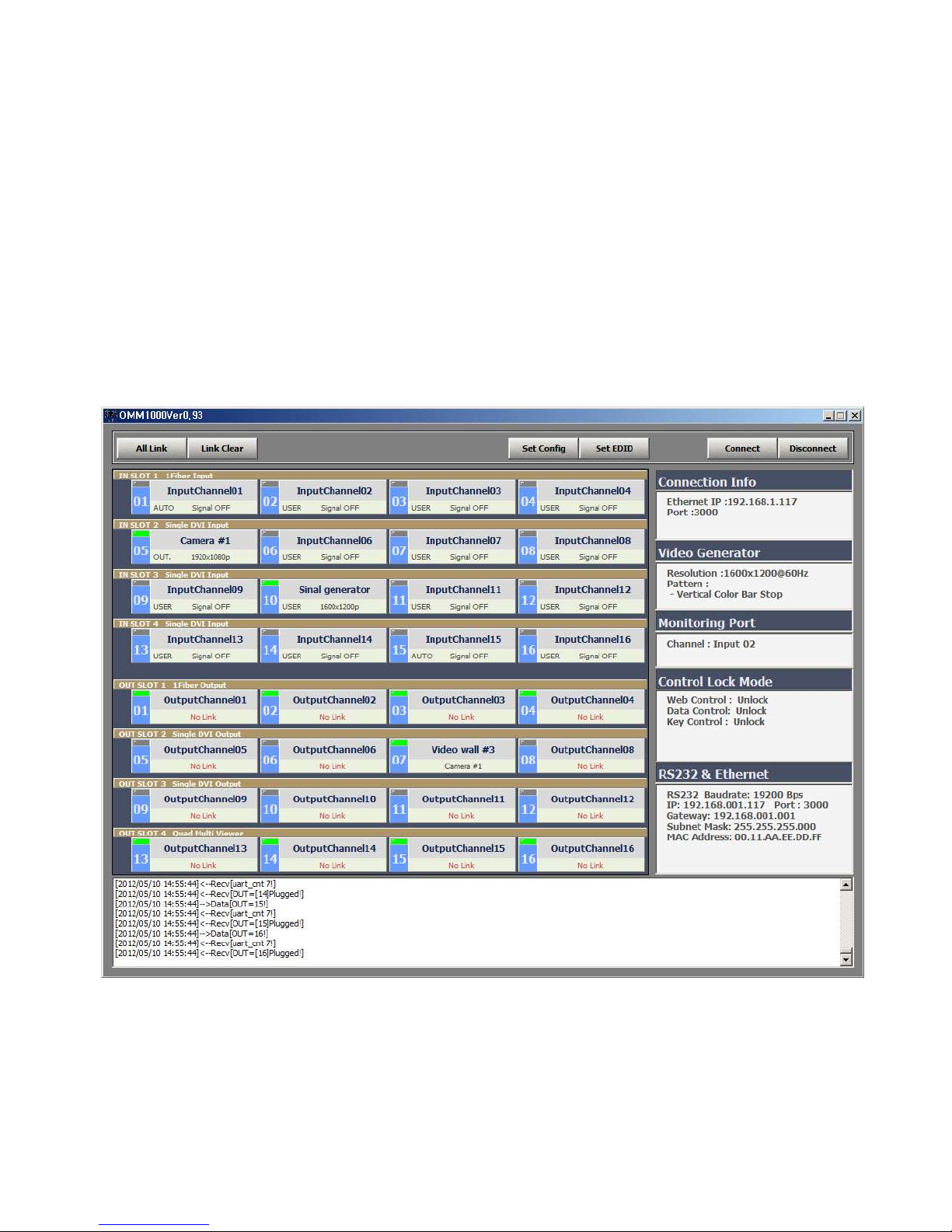
The PC program provides a user-friendly graphic interface alternative to key button input and
command input operation.
Copy OMM ver1.x.exe file in any directories in your PC and double click it to run. Then, initial window
of PC program for OMM-1000 as below will open.
Fig 4-1 PC program of OMM-1000
Page 20
20
4.1 Basic setup
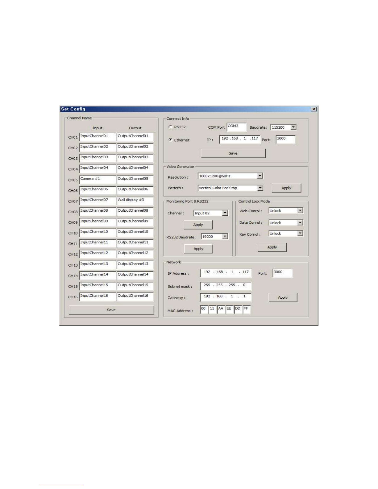
Click Set Config button to set the communication method, input / output name, Video generator and
so on. Then, the Set Config window as below will open.
Fig 4-2 Set Config window of OMM-1000 PC program
4.1.1 Connect Info
▪ Select the way of control method between RS-232 and Ethernet (UDP) by click the radio
buttons.
▪ In case of RS-232 control, enter available COM port number of your PC and select baud
rate. The baud rate should be same as that OMM-1000. (115200 is default)
▪ In case of Ethernet, enter IP address of OMM-1000 and port number. 3000 is default port
number of OMM-1000.
▪ Click save button and close Set Config window then click Connect button on PC program
of OMM-1000 to start it.
▪ If the connection is properly made, current status of OMM-1000 will be shown at the
Page 21
21
bottom side of PC program.
4.1.2 Channel Name
▪ User can allocate specific names for all inputs and outputs to distinguish them
▪ On Fig 4.2, The name of Camera #1 was assigned for Input CH05 and Wall display #3 for
output CH07.
▪ Click Save button to save it then, these will be applied on the PC program as shown in Fig
4-1.
4.1.3 Video Generator
▪ Select the resolution and pattern of video generator.
▪ Click Apply button to save it.
4.1.4 Control Lock Mode
▪ It locks and unlocks the controls such as Web, Data control (RS-232, TCP/IP and UDP)
and key button input.
▪ Click Apply button to save it.
4.1.5 Network
▪ It changes network information of OMM-1000.
▪ Click Apply button to save it.
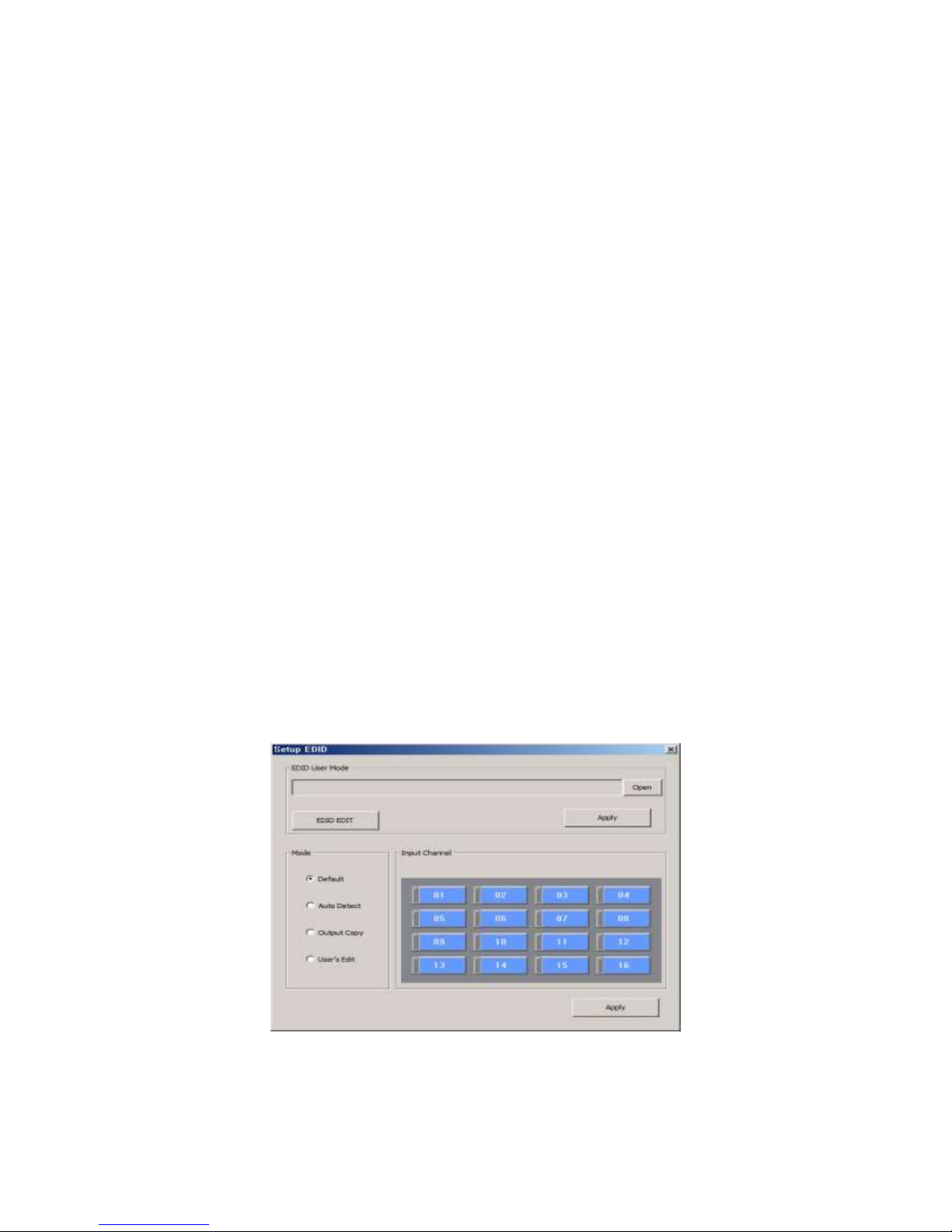
4.2 EDID setup
OMM-1000 offers 3 types of EDID setting for easy installation with various displays in the market.
To set the EDID option for each input port, click Set EDID button then, Setup EDID window as
below will open.
Fig 4-3 Setup EDID window of OMM-1000 PC program
To set EDID information for each input select mode button and click input channel. For each
Page 22
22
mode, multi-input channels can be allocated.
▪ Default mode is default EDID from the factory. By selecting it, default EDID will be
recovered for allocated input channels.
▪ Auto Mix mode is the most advanced one it analyzes all EDID of attached displays at the
output ports of OMM-1000 and get optimized EDID. By selecting it, user can avoid any
compliance problems in the field.
▪ Output Copy mode is most popular one. It reads EDID from any target displays and
copies it in input port. Select output channel first and click input channels. And click Apply
button to save it.
There is User’s Edit mode but it is used to modify existing EDID to make new EDID working
with specific systems. It is not recommended for general user. For further information, please
contact [email protected]
4.3 Operation
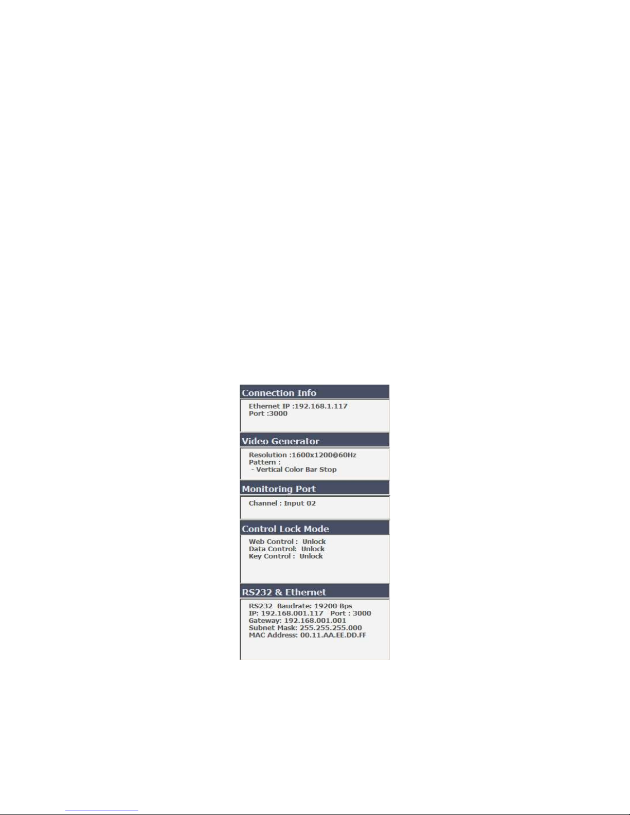
And all of setting parameters will be shown on the right side of PC program as Fig 4-3. After
clicking Connect button (Refer to Chap. 4.1.1), OMM-1000 is ready to get the command from
user.
The right side of PC program shows various connection status such as input / output
Fig 4-4 Setting parameters of OMM-1000
Page 23
23
connections, Input signal resolution and status, EDID setting for each input and Input / output
card information and used to make new input / output connections too.
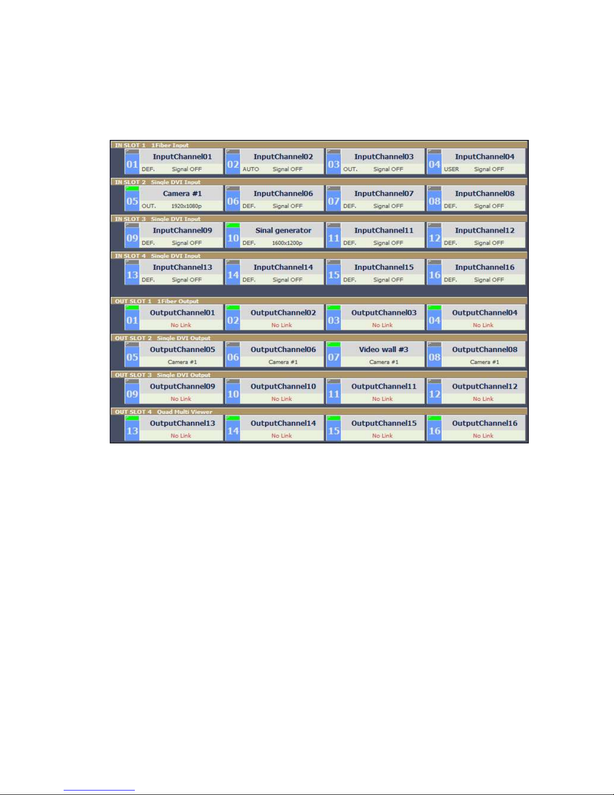
4.3.1 Input / output connection
▪ Click one of input channels and click any of output channels. If you click input CH05
(Camera #1) and click output CH05, CH06, CH07 and CH06 input signal 05 will be
connected to output monitor 05, 06, 07 and 08 as shown in Fig 4-5.
▪ To connect one input to all output, click All Link button and click desired input. Then all of
output will be connected to it.
▪ To disconnect all outputs, click Link Clear button.
4.3.2 Input channel status
▪ Green LEDs above input channel number such as CH05 and CH10 are signal detection
from source. It means only CH05 and CH10 are connected with video sources.
▪ If the green LED lit ON, user can recognize the resolution of input signal (ex.
CH05=1920x1080p).
▪ If LED OFF, sources are not connected and it shows ‘Signal OFF’.
▪ DEF., AUTO, OUT. and USER, right side of input channel number are EDID mode that is
allocated for each input (Refer to Chap. 4.2)
Fig 4-5 Input and output status of OMM-1000
Page 24

24
▪ There are 4 slots for input cards and OMM-1000 recognizes its type during booting
[Pattern 4]
Input #4
[1st layout]
[3rd layout]
[2nd layout]
[6th layout]
[4
th
layout]
[7th layout]
[5th layout]
2nd input
1st input
4th input
3rd input
1st input
3rd input
2nd input
4th input
1st input 1st input
1st input
2nd
3rd
4th
2nd
3rd
4th
process and shows it on PC program when it launched. (Ex. Slot 1 is fiber optic input card,
SDVI-1FI and Slot 2 is electrical DVI input card, SDVI-4EI)
4.3.3 Output channel status
▪ Green LEDs above output channel number such as CH07 is Hot Plug Detection (HPD)
from display. It means CH07 is connected with display.
▪ But in case of fiber optic card (slot 1), multi-viewer card (slot 4) and SDI output channel
LEDs are lit ON regardless of HPD.
▪ The connected outputs show input source information (ex. CH07=Camera #1, input CH05).
▪ The disconnected outputs show ‘No Link’.
▪ There are 4 slots for output cards and OMM-1000 recognizes its type during booting
process and shows it on PC program when it launched. (Ex. Slot 1 is fiber optic output card,
SDVI-1F0 and Slot 2 is electrical DVI output card, SDVI-4EO)
4.3.4 Multi-viewer
▪ The most outstanding feature of OMM-1000 is embedded multi-viewer card, QDVI-O.
▪ Multi-viewer card, QDVI-O can choose 4 inputs among 16 inputs of OMM-1000 and
configure and output these input signals with 7 different layouts.
1st layout: Select 1st input of QDVI-O and output it on a full screen
2nd layout: Select 2nd input of QDVI-O and output it on a full screen
3rd layout: Select 3rd input of QDVI-O and output it on a full screen
4th layout: Select 4th input of QDVI-O and output it on a full screen
5th layout: Make quad-view of 4 inputs (same size)
6th layout: Set 1
Fig 4-6 Layouts of Multi-viewer
st
input on the left side and other 3 on the right side
Page 25
25
7th layout: Set 1
B D A C A
B
C
D
Change
Input / output connection of OMM-1000
▪ QDVI-O can be inserted one of output slots and it will be shown on PC program as in Fig
4-5 (Out slot 4).
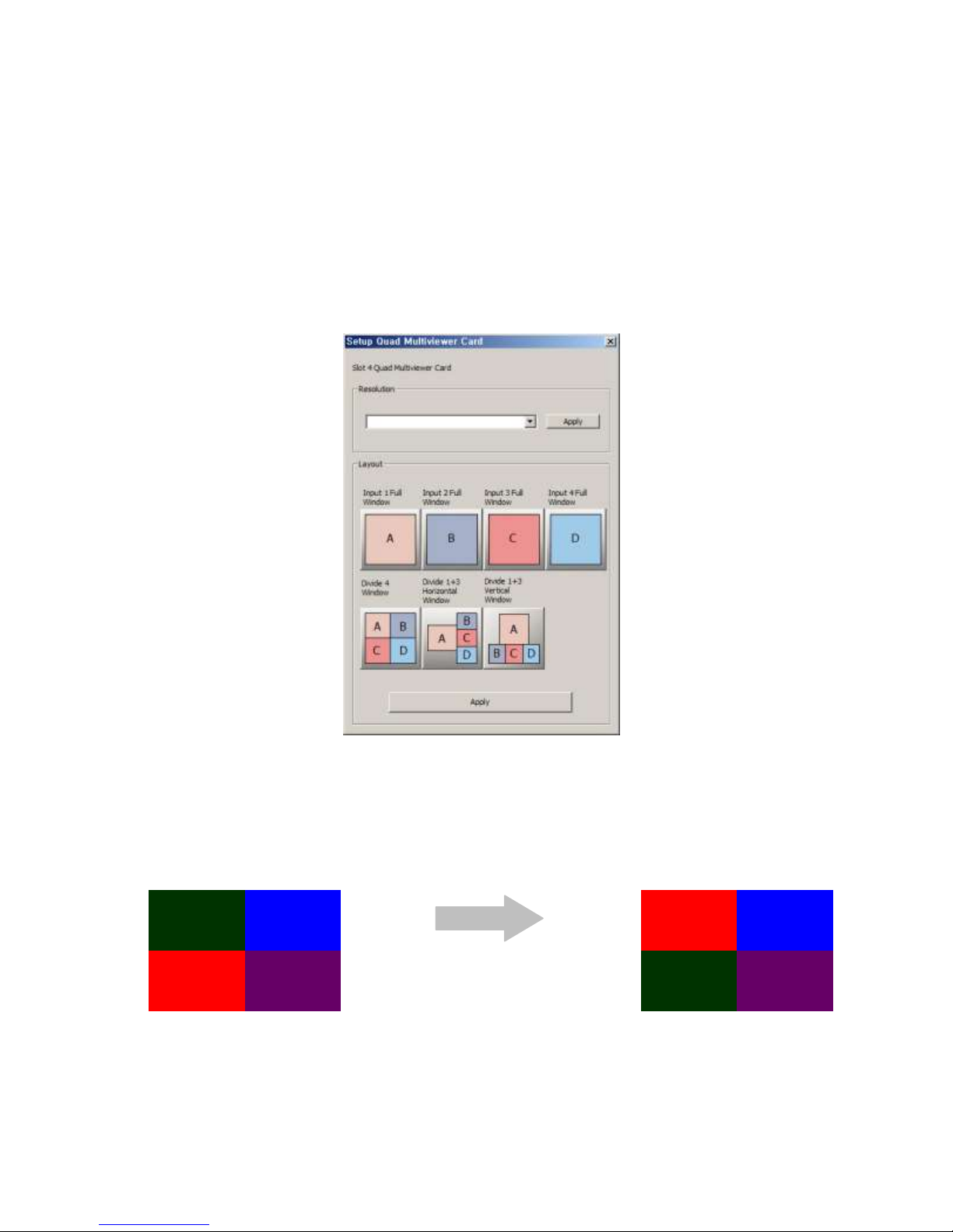
▪ Click OUT SLOT 4 bar to launch Setup Quad Multiviewer Card window as shown in Fig 4-
7.
▪ Select output resolution of multi-viewer card first.
▪ Select output layout.
st
input on the top side and other 3 on the bottom side
Fig 4-7 Multi-viewer card setup
[Note] 1. Changing the output resolution and layout of multi-viewer card, QDVI-O can be done by
PC program and command input and key button operation.
2. To change position of window in layout 5, 6 and 7, user must change the order of input to
QDVI-O. For example, If the QDVI-O is in output slot 2, to change window position of
layout 5 as shown in Fig 4-8, user must change input output connection.
Fig 4-8 Changing widow position of layout
In Fig 4-8, Video source A is output 5 of OMM-1000 and it is also the 1st input to QDVI-O
Page 26

26
and source C is output 7 of OMM-1000 and the 3rd input of QDVI-O. To change A and C,
user makes source A be connected to output 7 of OMM-1000 (It will be the 3rd input of
QDVI-O) then, source A will be shown on the bottom left side of layout 5. As the same
method, if user allocate source C to output 5 of OMM-1000, it will be shown on the top left
side.
3. Scale-down error will happen when the number of scale-down vertical pixels are less
than 1/5 (Progressive input case) or 1/4 (Interlaced input case) of original input
vertical pixels. For example, in case of layout 6, if you use input resolution, 1280x1024
and set the output resolution of QDVI-O at 800x600, the number of vertical pixels of 1st
2nd and 3
rd
inputs will be fitted into one third of output vertical pixels (600). In this case,
there would be an error because the number of scale-down vertical pixels, 200 (600/3) is
less than 204.8 (1024/5).
Page 27
27
Chapter 5. Web control panel operation
The Web control panel operation provides a user-friendly graphic interface and easy access to control
OMM-1000, if the PC is connected to Ethernet. But the functions are a little bit limited comparing with
other methods.
The OMM-1000 supports standard web browser but Microsoft Explorer is highly recommended to run
OMM-100 stably. Before running the web browser to control OMM-1000, please confirm that Network
setting of OMM-1000 and Ethernet connection of the PC (Refer to Chap 2 and Chap 3).
Launch the web browser and enter the IP address of current OMM-1000 into the URL address line.
For example, if the IP address of OMM-1000 is set as 192.168.001.117, jut type 192.168.1.117.
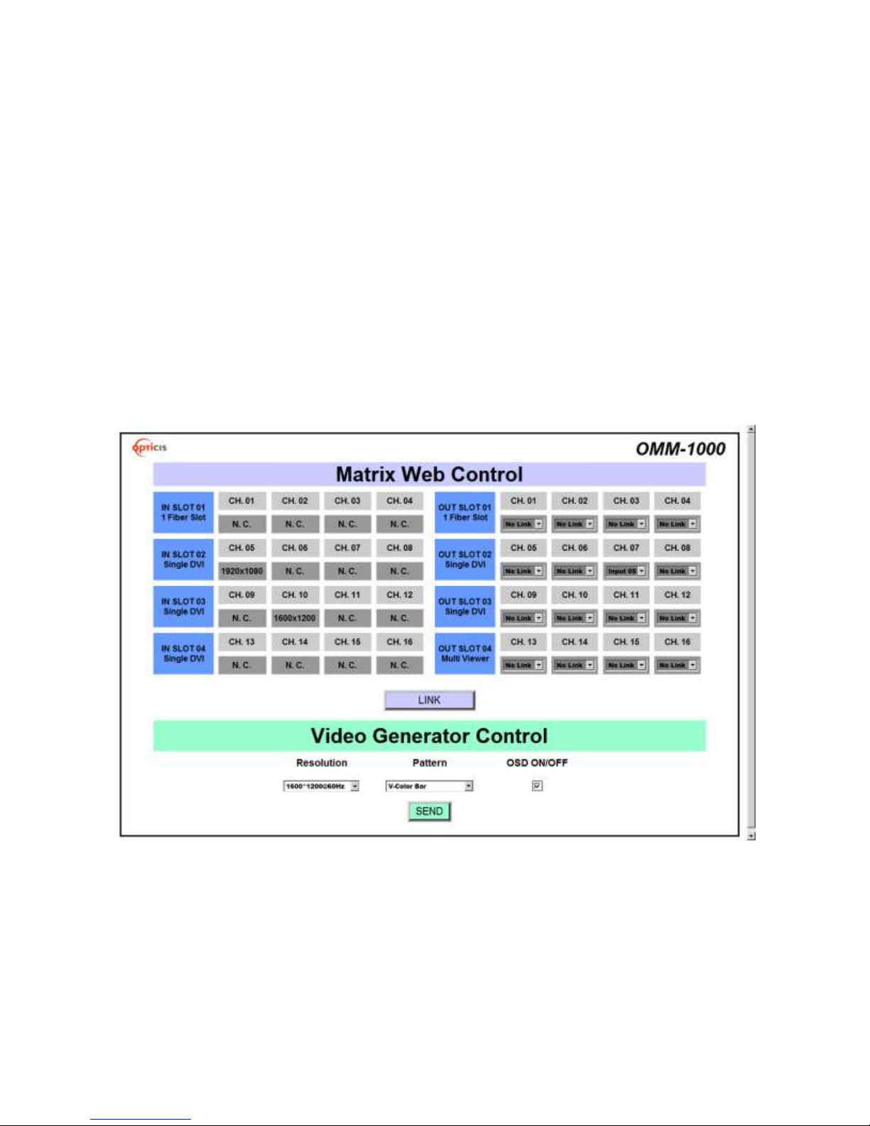
Fig 5-1 shows structure of Web control panel. It controls input / output connection and vide generator
and informs simple input / output status. Please remind that after new input /output connection, user
has to click LINK button and SEND button for new generator setting.
Fig 5-1 Web control panel
Page 28

28
Command
Description
LINK
Input and Output connection
IN
Input signal status request
OUT
Output signal status request
NET
Network information request
NETGW
Gateway address setting
NETSN
Subnet mask address setting
NETIP
IP address setting
NETPA
MAC address setting
NETPT
UDP port number setting
VID
Video generator status request
VIDRES
Video generator resolution setting
VIDIMG
Video generator pattern setting
MON
Monitoring port setting and status request
EDID
EDID mode setting
EDIT
Edited EDID transferring
RS232
RS-232 Baud rate setting
QUAD
Quad-viewer card status request
QUADRES
Quad-viewer card output resolution setting
QUADLAY
Quad-viewer card layout setting
SLOT
Input output slot status request
LOCK
Lock/Unlock the control type
Chapter 6. Command input operation
The OMM-1000 modular matrix could be operated with various interfaces such as key button inputs,
command input through RS-232 and TCP/IP, Web control through TCP/IP and PC program through
RS-232 and UDP. All functions are executed on a basis of a serial command input, but the graphic
interfaces on the Web or the PC program make more efficient way to operate the OMM-1000 modular
matrix.
Command input operation is accomplished through RS-232 or TCP/IP. For setting procedures for
those protocols, please refer to Chap 2 and Chap 3.
6.1 Command input structure
The command inputs are composed of a string of ASCII codes and its basic structure is;
Command + Delimiter (‘=’) + Data + Delimiter (‘^’ or ‘,’ or ‘_’) + Data + End (‘!’)
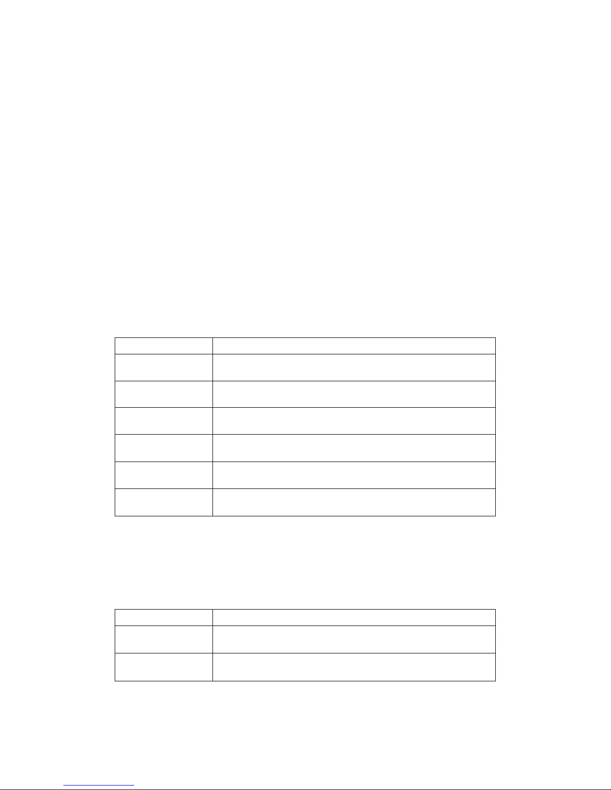
Table 6.1 shows all commands and its brief descriptions
Table 6.1 Commands set
Page 29
29
▪ The command input allows executing only one command. Multiple command inputs require
Command
Description and reply
LINK=01^10!
Makes input 1 connected to output 10.
Reply: LINK=01^10!
LINK =1^03,04^7!
Makes input 1 connected to output 3 and 4 to 7.
Reply: LINK =01^03,04^07!
LINK =05!
Makes input 5 connected to all outputs.
Reply: LINK=05!
LINK =00!
Makes all connections disconnected.
Reply: LINK =00!
LINK =00^06!
Makes output 6 disconnected.
Reply: LINK =00^06!
Link=?!
Requests current inputs and outputs connections status.
Reply: LINK =01^01,02^04,~16^13!
Command
Description and reply
IN=05!
Requests input 5 status.
Reply: IN=[05] 1920x1200p! or IN=[05] Signal Off!
OUTPUT=12!
Requests output 12 status.
Reply: OUT=[12] Un Plugged! or OUT=[12] Plugged!
executing multiple strings having each command per a string.
▪ User can use capital letters and small letters for commands but cannot mix it like ‘Link’, it
must be corrected as ‘link’ or ‘LINK’.
▪ After all input commands, OMM-1000 sends back replies to conform the execution of
commands.
▪ Input and output port number range from 1 to 16 and prefix, ‘0’ can be used such as ‘001’
and ‘010, but in the replies after the command inputs, the digits of port number are two such
as ‘01’ and ‘10’.
6.2 Examples of command inputs
6.2.1 Link input and output
▪ It makes single or multi-connections of inputs and outputs.
▪ It makes disconnection of all inputs when used with ‘0’.
▪ It requests inputs and outputs status of OMM-1000.
Table 6.2 Link command examples
6.2.2 Input and output status
▪ It requests input signal status. If the input is connected, it replies input resolution, but if it is
not connected, it returns ‘Signal Off’.
▪ It requests output status whether it is connected to display or not.
Table 6.3 Input and output status command examples
Page 30
30
Command
Description and reply
NETGW=192.168.1.1!
Sets Gateway address, each data ranges from 000 to 255.
Reply: NETGW=192.168.001.001!
NETIP=192.168.1.118!
Sets IP address, each data ranges from 000 to 255.
Reply: NETGW=192.168.001.118!
NETSN=255.255.255.0!
Sets Subnet mask address, each data ranges from 000 to 255.
Reply: NETSN=255.255.255.000!
NETPA=AA.BB.CC.DD.EE.FF!
Sets MAC address, each data ranges from 00 to FF.
Reply: NETPA= AA.BB.CC.DD.EE.FF!
NETPT=3000!
Sets UDP port number, data ranges from 0 to 65535.
NETPT=3000!
NET=?!
Requests current network setting.
Reply: NETGW=192.168.001.001!
NETIP=192.168.001.118!
NETSN=255.255.255.000!
NETPA=AA.BB.CC.DD.EE.FF!
NETPT=3000!
Data #
Resolution
Pattern
1
800x600@60Hz
Vertical Color Bar
2
1024x768@60Hz
Vertical Color Bar scroll (Interval:0.5sec)
3
1280x960@60Hz
Vertical Color Bar scroll (Interval:1.0sec)
4
1280x1024@60Hz
Horizontal Color Bar
5
1600x1200@60Hz
Horizontal Color Bar scroll (Interval:0.5sec)
6.2.3 Network setting
▪ It sets IP, Gateway, Subnet mask, MAC address and UDP port number.
▪ It requests current network setting.
6.2.4 Video generator setting
▪ It changes resolution and pattern of video generator.
▪ It requests current video generator setting.
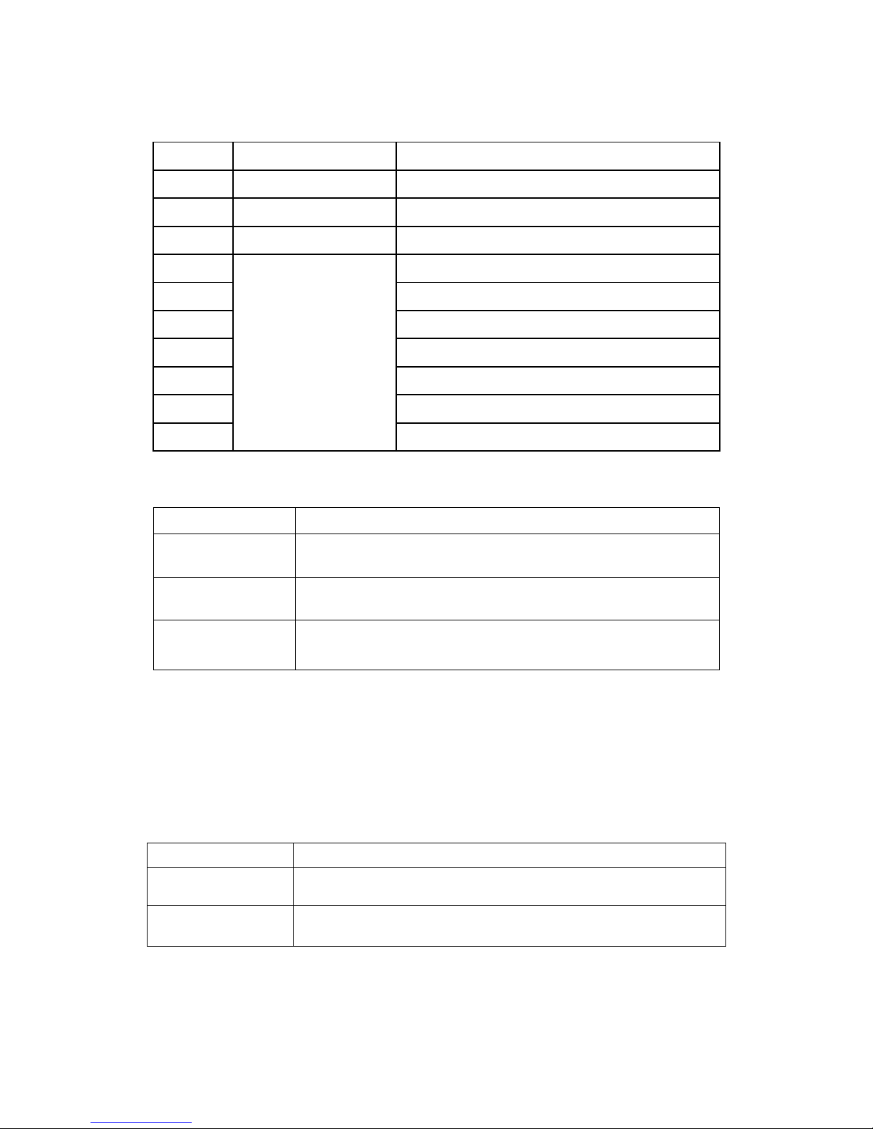
Table 6.5 describes the resolutions and patterns OMM-1000 supports. By command input
operation, user can change these to be used with on-site source for easy installation
Table 6.4 Network setting command examples
Page 31
31
6
1920x1200@60Hz
Horizontal Color Bar scroll (Interval:1.0sec)
7
1280x720p@60Hz
Full White
8
1920x1080i@60Hz
Full Yellow
9
1920x1080p@60Hz
Full Cyan
10
Full Green
11
Full Magenta
12
Full Red
13
Full Blue
14
Full Gray
15
Cross Hatch 16x16
16
Grayscale bars
Command
Description and reply
VIDRES=4!
Sets video generator resolution by data #4.
Reply: VIDRES=1280x1024@60HZ!
VIDIMG=3!
Sets video generator pattern by data #3.
Reply: VIDIMG=VCOLORBAR10SMOVE!
VID=?!
Requests current video generator resolution and pattern.
Reply: VID=04_03!
(it means data #4 resolution and data #3 pattern)
Command
Description and reply
MON=13!
Makes input 13 connected to monitor output ports.
Reply: MON=13!
MON=?!
Requests current input port that connected to monitor output port.
Reply: MON=13!
Table 6.5 Video generator resolutions and patterns
Table 6.6 Video generator command examples
6.2.5 Monitor output port setting
▪ It makes input to connected to monitor output port.
▪ It requests current input port that connected to monitor output port.
Table 6.7 Monitor output setting command examples
Page 32
32
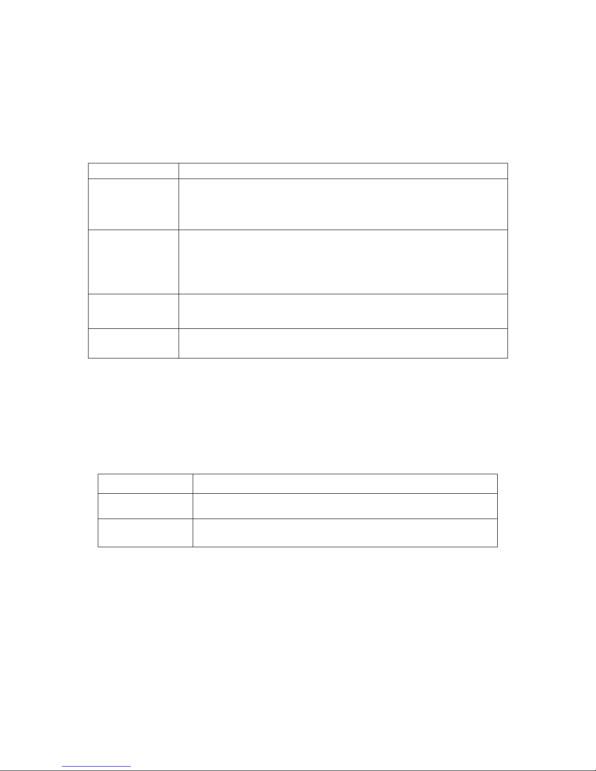
6.2.6 EDID control command
Command
Description and reply
EDID=DE1,7,15!
Default mode: Saves default EDID in input ports 1, 7 and 15.
Reply: EDID=01DEF.!
EDID=07DEF.!
EDID=15DEF.!
EDID=AUTO2,8,9!
Auto mix mode: Analyzes all EDID information of connected displays to
makes optimized EDID then save it in input ports 2, 8 and 9.
Reply: EDID=02AUTO!
EDID=08AUTO!
EDID=09AUTO!
EDID=OUT3_5!
Output copy mode: Copies EDID information of output 3 display and
stores it in input port 5.
Reply: EDID=03OUT.!
EDID=?!
Requests current EDID setting for all inputs.
Reply: EDID=01OUT.02AUTO03OUT.~16EDF.!
Command
Description and reply
RS232=115200!
Sets RS-232 baud rate.
Reply: RS232=115200BPS!
RS232=?!
Requests current baud rate.
Reply: RS232=115200BPS!
▪ It stores EDID information in input port of OMM-1000.
▪ It requests current EDID setting for all input ports.
Table 6.8 Monitor output setting command examples
6.2.7 Baud rate setting for RS-232
▪ It sets RS-232 baud rate. OMM-1000 supports 9600, 19200, 38400, 57600, 115200bps.
▪ It requests current RS-232 baud rate.
Table 6.9 Baud rate setting command examples
Page 33
33
6.2.8 Multi-viewer card (QDVI-O) setting
Data #
Resolution
Layout
1
800x600@60Hz
1st input of QDVI-O on a full screen
2
1024x768@60Hz
2nd input of QDVI-O on a full screen
3
1280x960@60Hz
3rd input of QDVI-O on a full screen
4
1280x1024@60Hz
4th input of QDVI-O on a full screen
5
1600x1200@60Hz
Quad-screen
6
1920x1200@60Hz
1 Large screen (Left side) + 3 Small screen (Right side)
7
1280x720p@60Hz
1 Large screen (Top side) + 3 small screen (Bottom side)
8
-
-
9
1920x1080p@60Hz
-
Command
Description and reply
QUADRES=3_9!
Sets output resolution of QDVI-O at 1920x1080P. In this case,
QDVI-O is inserted in 3rd slot of output bay.
Reply: QUADRES=03_09!
QUADLAY=1_5!
Sets layout of QDVI-O as quad-screen. In this case, QDVI-O is
inserted in 1st slot of output bay.
Reply: QUADLAY=01_05!
QUAD=?!
Request current status of QDVI-O. If one QDVI-O is inserted in 2nd
slot and output resolution is 1600x1200@60Hz with layout #6:
Reply: QUAD=01_00_00,02_05_06,03_00_00,04_00_00!
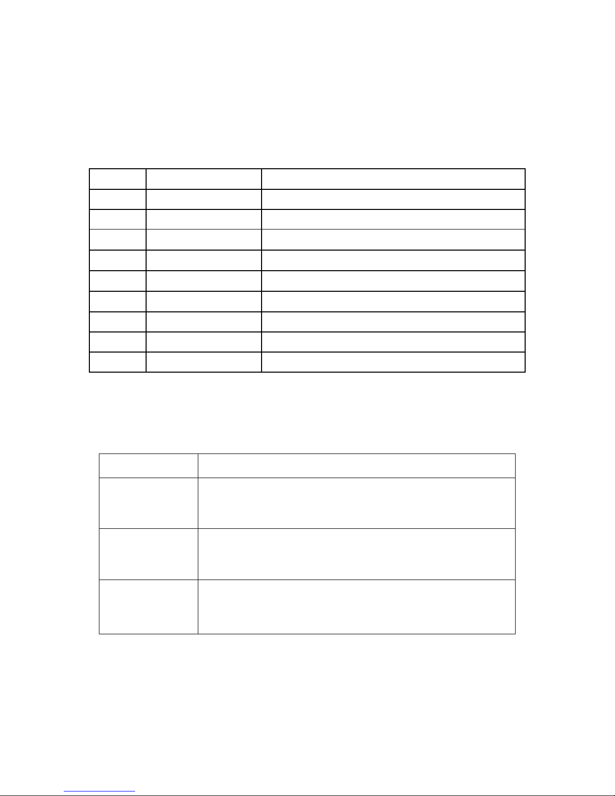
▪ It sets output resolution and layout of QDVI-O.
▪ It requests current status of QDVI-O.
Table 6.10 Supporting resolutions and layouts of QDVI-O
The first numeric data in command line represents slot number of output bay of OMM-1000
where QDVI-O is inserted.
Table 6.11 Multi-viewer card setting command examples
Page 34
34
6.2.9 Slot status request
Data
Card type
Data
Card type
02
Single DVI input card, SDVI-4EI
12
SDI input card, SDI-4EI
03
Single DVI output card, SDVI-4EO
13
SDI output card, SDI-4EO
18
1 Fiber DVI input card, SDVI-IFI
0C
DisplayPort input card, DP1-4EI
19
1 Fiber DVI output card, SDVI-1FO
0D
DisplayPort output card, DP1-4EO
21
Multi-viewer card, QDVI-O
1A
Reserved
0A
HDMI input card, HDMI-4EI
1B
Reserved
0B
HDMI output card, HDMI-4EO
-
Command
Description and reply
SLOT=?!
Requests current cards type in input and output bay.
OMM-1000 has 4 rows of input and output slots. If the input output
cards are configured as below:
1st row: Single DVI input card / 1 Fiber DVI output card
2nd row: Single DVI input card / Multi-viewer card
3rd row: 1 Fiber DVI input card / Single DVI output card
4th row: 1 Fiber DVI input card / NO output card
Reply: SLOT=01_02_19!
SLOT=02_02_21!
SLOT=03_18_03!
SLOT=04_18_00!
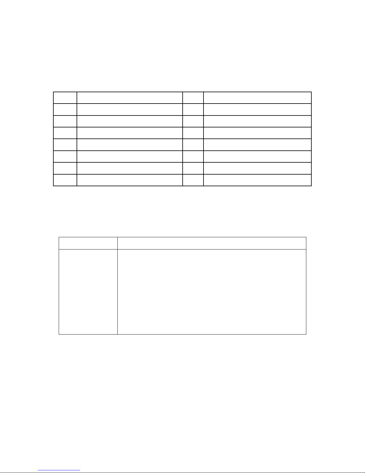
▪ It requests current cards type in input and output bay.
The first numeric data in reply represents the order row of slot and second and third data
represents type of input and output cards.
Table 6.12 Card types and its data
Table 6.13 Slot status request command example
Page 35
35
ASCII
Description
WL
Web control lock
WUL
Web control unlock
DL
Data control (UDP, TCP/IP, RS-232) lock
DUL
Data control (UDP, TCP/IP, RS-232) unlock
KL
Key control lock
KUL
Key control unlock
Command
Description and reply
LOCK=DL!
Locks data control.
Reply: LOCK=DL!
LOCK=?!
Request current status of control method.
Reply: LOCK=WUL,DUL,KUL!
Command
Description and reply
PRE=SAVE<Preset Number>!
Requests to save the current routings under the preset number selected.
Reply: PRE=SAVE<Preset Number>_<link state>!
Example:
Send: PRE=SAVE01!
Reply: PRE=SAVE01_00^01,00^02,00^03,00^04......00^16!
(04^04 indicates input 4 linked to output 4. Input 00 indicates no link set
for the output)
PRE=LOAD<Preset Number>!
Requests to load the saved preset number.
Reply: PRE=LOAD<Preset Number>_<link state>!
Example:
Send: PRE=LOAD01!
Reply: PRE=LOAD01_00^01,00^02,00^03,00^04......00^16!
6.2.10 Control lock command
▪ It locks and unlocks the controls such as Web, RS-232, TCP/IP and UDP.
▪ It request open status of controls.
Table 6.14 Locking type and its ASCII data
6.2.11 Preset Control Commend
▪ It saves routings under a preset number
▪ It requests current Preset mode setting.
Table 6.15 Control lock command examples
Table 6.16 Preset control command examples
Page 36
36
①
②
③
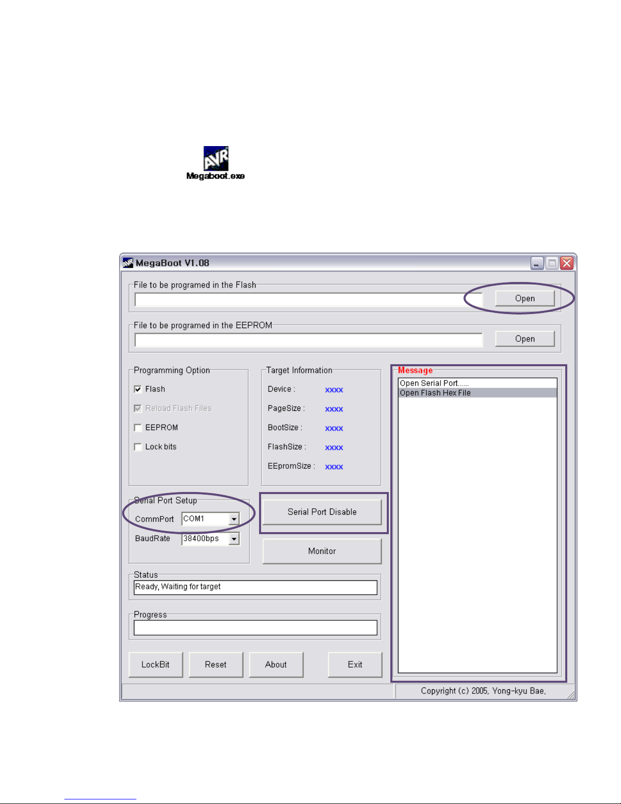
Chapter 7. Firmware update
1. Please install under Windows XP OS.
[Note] Megaboot.exe can’t be installed under Windows 7 and Vista OS.
2. Click ①, Open of ‘File to be programmed in the Flash’ to select directory and file (hex.
Format) to be uploaded.
Page 37
37
3. Connect Service Port in a rear panel of OMM-1000 RS-232 (Comm port) in PC using a
supplied download cable (RJ11 to D-Sub 9Pin cable) + RS-232 cable.
4. Select ②, ‘Comm port’ to select communication port of PC for RS-232 communication with
OMM-1000.
5. To enable Comm port, Click ③ when it shown as ‘Serial Port Enable’.
6. Power-On of OMM-1000.
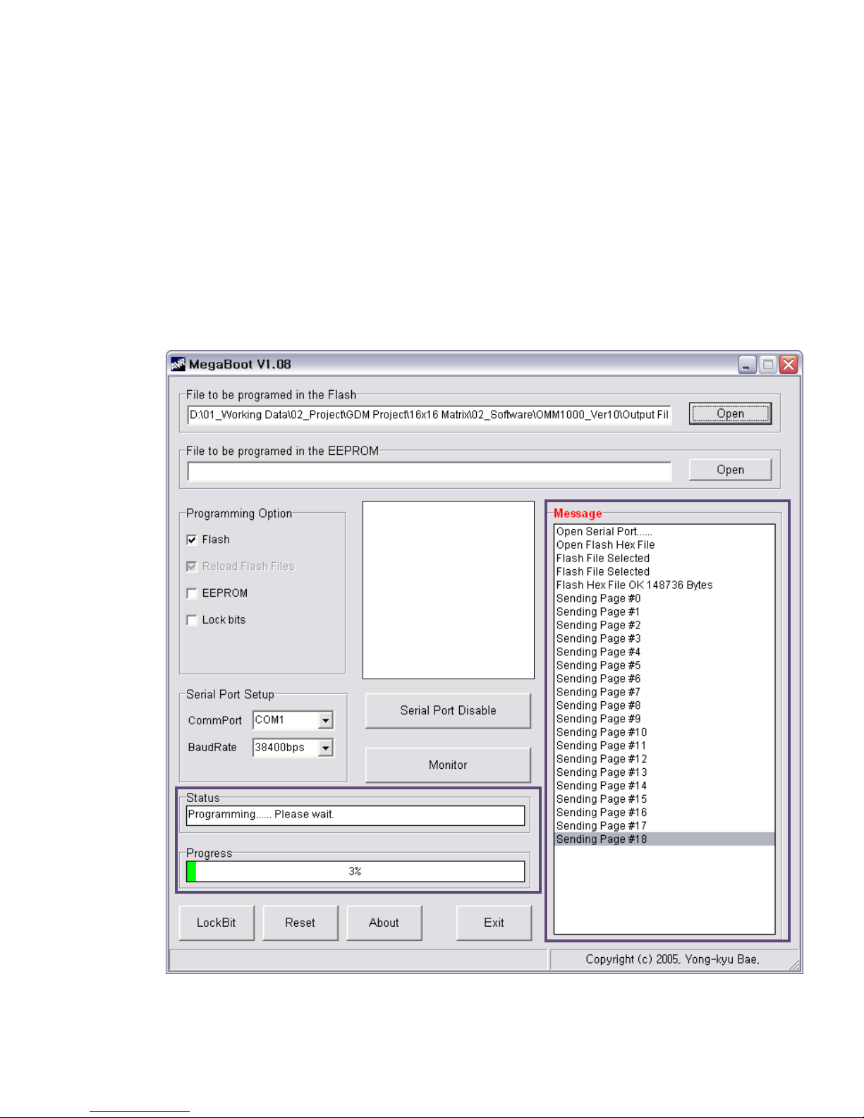
7. Then the firmware will be uploaded and its status will be shown in the message box shown as
below.
Page 38
38
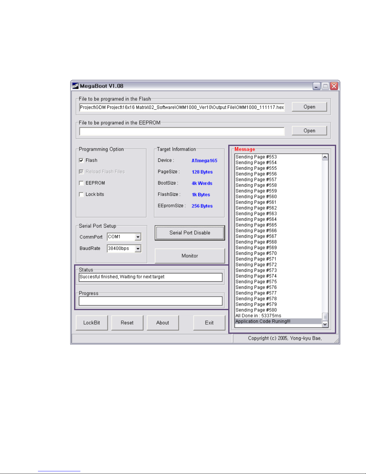
8. After 3~4 minutes, Application Code Runing!!! message will be shown. Then the firmware
upload is completed.
9. Please close a megabox.exe program and reboot OMM-1000 to run it under new
firmware.
Page 39
39
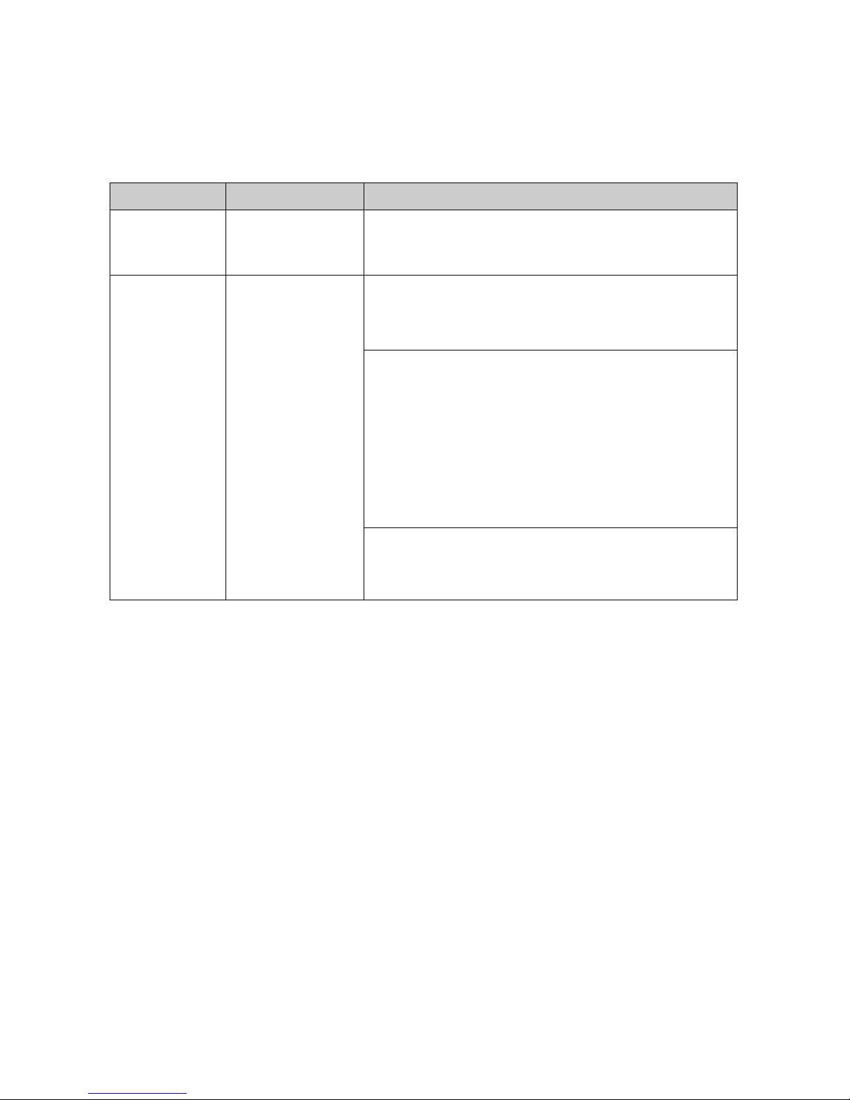
Chapter 8. Trouble shooting
Problem
Symptom
Solution
No Power
Power LED Off
Check the connection of power cord to the OMM-1000
and AC power outlet and that make sure that power
switch is in the ON.
No Output
No Output present
Check the Input Output DVI cables are firmly connected to
each port of OMM-1000.
Check the Input and Output connection configuration you
want.
The display is not capable of handling graphic
resolution.
Check the compatibility of EDID in the EEPROM and
attached displays.
When a single Input is routed to multiple outputs,
lower resolution EDID should be selected.
EX> Input 1 Output 1 (UXGA) & Output 2(SXGA)
If EEPROM 1 store the display 1 EDID (UXGA), the
display 2 (SXGA) will not work due to resolution limit.
The source has stopped sending a graphic signal.
Check the Input source status by connecting it to available
monitor without the OMM-1000.
Page 40
40
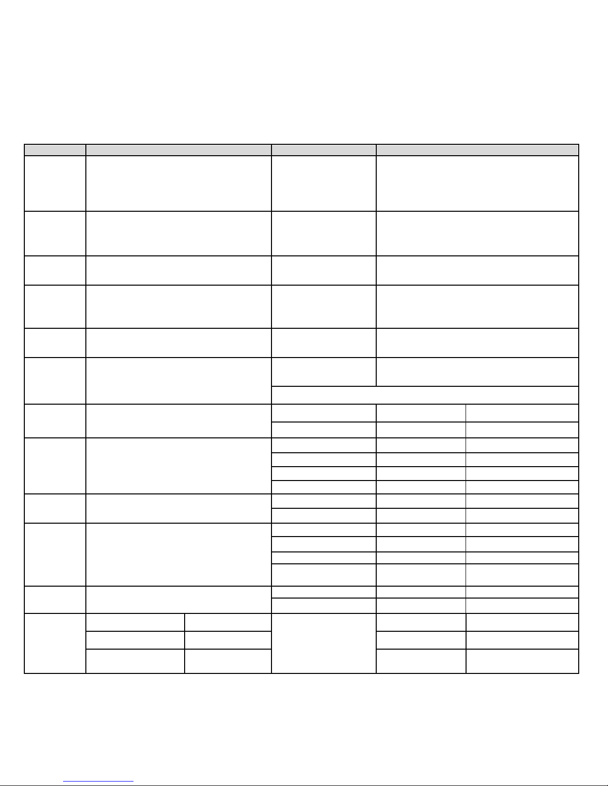
Section
Basic Spec.
Section
Basic Spec.
Video
resolution
Main VESA resolution & Main vertical
frequency from 640x480 up to WUXGA
(1920x1200), @60Hz
WQXGA (2560x1600),@60Hz (Dual link ,
DisplayPort card only)
Reference video output
9 output video resolutions with 16 patterns
HDCP
Support : Electric DVI, Dual link DVI, HDMI
Non-support : Optical DVI, SDI, DisplayPort
Diagnosis
1) In/Output Link condition
2) source & display Link condition
3) EDID, HDCP information by the remote control
through the Web
Video format
conversion
Video format conversion without scaling
function
Configuration
Save & Restore for Current connection & Control
condition by internal memory
Multi -viewer
With additional output card (QDVI-O), Quad
view & picture in picture (PIP)
EDID management
1) Default Mode
2) Auto Mix Mode
3) Output Copy Mode
In/Output
16 x 16 (4 ports in one in/output card)
8 x 8 (2 ports in one in/output card)
Color
Black
Switching
speed
< 1 sec (If No format searching by Display)
Front Key
LED key (Use of long-term reliability prepared
product )
In/Output card Spec.
Size
440 x 380 x 178mm (WDH), (4U, 19”)
Section
Model name
In/Output port
Single DVI input
SDVI-4EI
4 x DVI-D receptacle
Weight
< 11Kg (net weight for single power)
Single DVI output
SDVI-4EO
4 x DVI-D receptacle
Dual DVI input
DDVI-2EI
2 x DVI-D receptacle
Dual DVI output
DDVI-2EO
2 x DVI-D receptacle
HDMI input
HDMI-4EI
4 x HDMI receptacle
Cooling
system
Cooling fan (Forced cooling system)
HDMI output
HDMI-4EO
4 x HDMI receptacle
SDI input
SDI-4EI
4 x SDI receptacle
Certificate
UL/EN 60601, CE, FCC class B
SDI output
SDI -4EO
4 x SDI receptacle
DisplayPort input
DP1-4EI
4 x DP receptacle
DisplayPort output
DP1-4EO
4 x DP receptacle
Quad output
QDVI-O
1x DVI-D receptacle
+ 1x SC receptacle
Control
system
Front-key, RS-232, TCP/IP, Web
1 fiber DVI input
SDVI-1FI
4 x SC receptacle
1fiber DVI output
SDVI-1FO
4 x SC receptacle
Operating
condition
Temperature (℃)
10 ~ 40
Transport
And
Storage condition
Temperature (℃)
-30 ~ +70
Relative humidity (%)
+30~ +75
Relative humidity (%)
+10~ +95
Atmospheric
Pressure (hPa)
700 ~ 1060
Atmospheric
Pressure (hPa)
500 ~1060
9.1 General specification
Chapter 9. Specification
Page 41

41
9.2 Power Specification
Input card
Output card
Input resolution
Output resolution
SDI card
SDI card
480i
720p@ 60
576i
720p@ 23.98
720p@ 30
720p@ 24
720p@ 50
720p@ 25
720p@ 59.94
720p@ 29.97
720p@ 60
1035i
720p@ 60
1080i, 1080sf
1080p@ 60
1080p@ 23.98
1080p @ 30
1080p@ 60
1080p@ 24
1080p @ 50
1080p@ 25
1080p @ 59.94
1080p@ 29.97
1080p @ 60
SDI card
HDMI, DVI,
Fiber card
480i
SXGA (1280x1024)
576i
720p@ 23.98
720p@ 30
720p@ 60
720p@ 24
720p@ 50
720p@ 25
720p@ 59.94
720p@ 29.97
720p@ 60
1035i
720p@ 60
1080i, 1080sf
1080p@ 60
1080p@ 23.98
1080p @ 30
1080p@ 60
1080p@ 24
1080p @ 50
1080p@ 25
1080p @ 59.94
1080p@ 29.97
1080p @ 60
HDMI, DVI,
Fiber card
SDI card
depends on
V display
720≤ V display <1080
720p@ 60
V display ≥1080
1080p@ 60
AC Power
1) Input Voltage : AC100-240V ±10%, 50/60Hz
2) Power consumption : 2.2-0.9A
3) Shall have a power cord that complies with regulatory requirements imposed by the country of
sale.
4) Incorporate a power cord management system for securing a bundled up cord.
External Fuse
1) Input Voltage: AC100-240V ±10%, 50/60Hz
2) Power consumption: 2.2-0.9A
3) F 6.3 AH250V
9.3 SDI video input and output scaling condition
[Note] Both SDI input and output card do not support audio signal.
Page 42
42
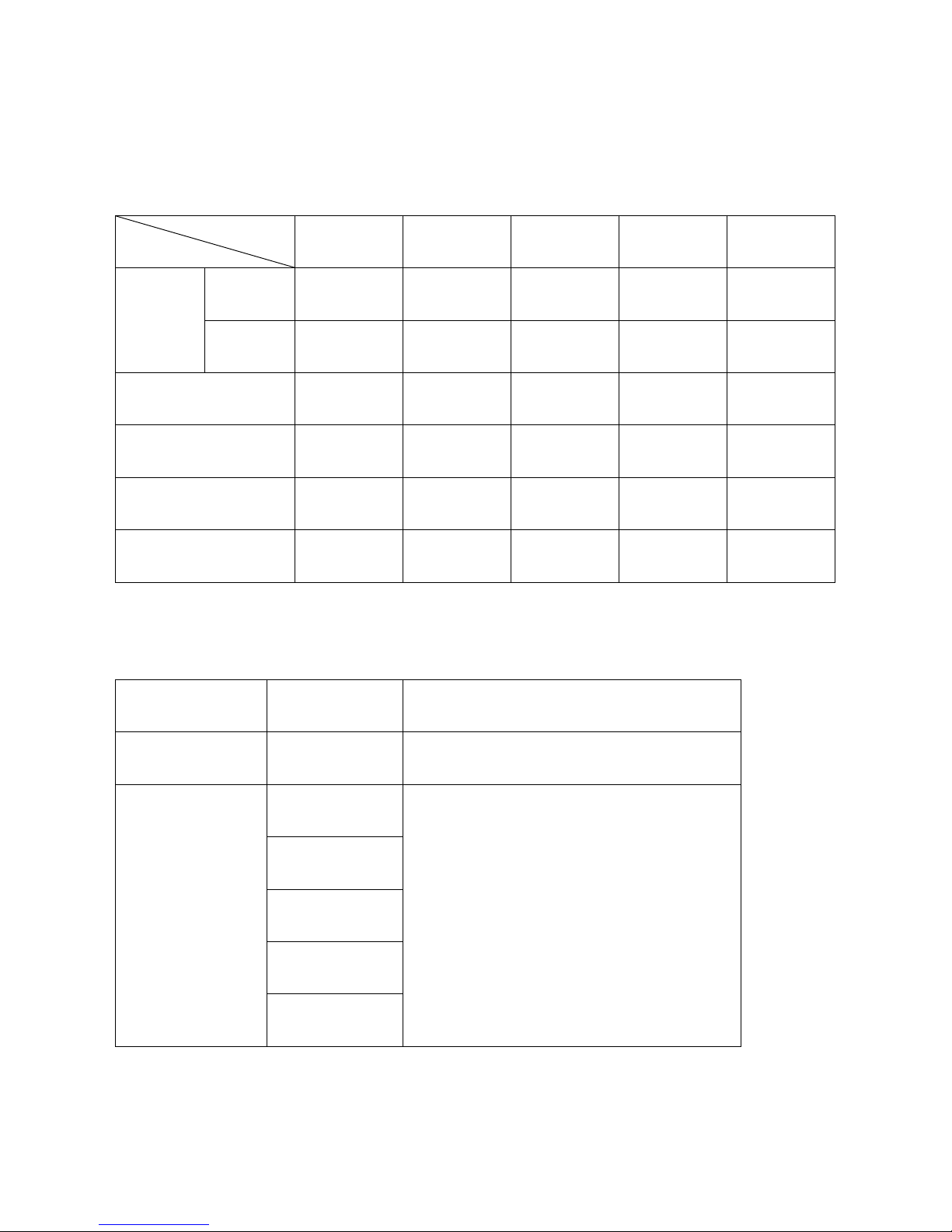
9.4 Compatibility between Dual link DVI In/Output cards and another
DDVI-2EO
SDVI-4EO
SDVI-1FO
HDMI-4EO
SDI -4EO
DDVI-2EI
Dual
DVI
Pass
N/D
N/D
N/D
N/D
Single
DVI
Pass
Pass
Pass
Pass
Pass
SDVI-4EI
Pass
Pass
Pass
Pass
Pass
SDVI-1FI
Pass
Pass
Pass
Pass
Pass
HDMI-4EI
N/D
Pass
Pass
Pass
Pass
SDI -4EI
N/D
Pass
Pass
Pass
Pass
Input card
Output card
Resolution
DP1-4EI
DP1-4EO
Up to WQXGA (2560x1600) at 60Hz
(Not support Deep color)
DP1-4EO
SDVI-1FO
Up to WQXGA (2560x1600) at 60Hz
SDVI-4EO
HDMI-4EO
SDI-4EO
DDVI-2EO
Input
Output
In/Output cards
9.5 Compatibility between DisplayPort In/Output cards and another
In/Output cards
Page 43

43
Chapter 10. Warranty Information
1 (One) Year Warranty
Opticis warrants this optical DVI extension module to be free from defects in workmanship and
materials, under normal use and service, for a period of one (1) year from the date of purchase from
Opticis or its authorized resellers.
If a product does not work as warranted during the applicable warranty period, Opticis shall, at its
option and expense, repair the defective product or part, deliver to customer an equivalent product or
part to replace the defective item, or refund to customer the purchase price paid for the defective
product.
This product should be serviced such as repair or replace by Opticis and please contact your reseller
or Opticis if you have any problems. All products that are replaced will become the property of Opticis.
Replacement products may be new or reconditioned.
Any replaced or repaired product or part has a ninety (90) day warranty or the reminder of the initial
warranty period, whichever is longer.
Opticis shall not be responsible for any software, firmware, information, or memory data of customer
contained in, stored on, or integrated with any products returned to Opticis for repair under warranty or
not.
Warranty Limitation and Exclusion
Opticis shall have no further obligation under the foregoing limited warranty if the product has been
damaged due to abuse, misuse, neglect, accident, unusual physical or electrical stress, unauthorized
modifications, tampering, alterations, or service other than by Opticis or its authorized agents, causes
other than from ordinary use or failure to properly use the product in the application for which said
product is intended.
Dispose of Old Electrical & Electronic Equipment
(Applicable in the European Union and other European countries with separate systems)
This marking shown the product or its literature, indicates that it should not be
disposed with other household wastes at the end of its working life. To prevent
Page 44
44
possible harm to the environment or human health from uncontrolled waste disposal,
please separate this from other types of wastes and recycle it responsibly to promote
the sustainable reuse of material resources.
Household users should contact either the retailer where they purchased this product, or their local
government office, for details of where and how they can take this item for environmentally safe
recycling.
Business users should contact their supplier and check the terms and conditions of the purchase
contract. This product should not be mixed with other commercial wastes for disposal
Chapter 11. Safety Instructions
WARNING: Do not touch signal input, signal output of other connectors, and the patient
simultaneously.
WARNING: Do not connect any accessory except provided by Opticis. Any damage caused other
power adapters or accessories will not be taken any responsibility by Opticis.
Warning for Medical usage
WARNING: External equipment intended for connection to signal input, signal output or other
connectors, shall comply with relevant IEC Standard (e.g., IEC60950 for IT equipment and IEC606011 series for medical electrical equipment). In addition, all such combination-system-shall comply with
the standard IEC60601-1 and/or IEC60601-1-1 harmonized national standard or the combination. If, in
doubt, contact a qualified technician or your local representative.
Page 45

45
WARNING: (Detachable) This unit uses plug for US: 120V rating 5-15P type only.
This system complies to the above standards only when used with the supplied medical grade power
supply.
Caution: Make sure the power cord is the correct type that is required in your area.
This system has a universal power supply that allows operation in either 100-120V AC or 200-240V
AC voltage areas (no user adjustment is required).
Use the proper power cord with correct attachment plug type. If the power source is 120V AC, use a
Hospital Grade Power Cord with NEMA 5-15 style plug, labeled for 125 volts AC with UL and C-UL
approvals.
If the power source is a 240 V AC supply, use the tandem (T blade) type attachment plug with ground
conductor power cord that meets the respective European country’s safety regulations.
The hospital-grade plug for medical products intended for use in Denmark has DEMKO approval and
is rated 13 amps at 250Vac. This plug is recommended for use in medical applications and
specifications are being added to the standard SB 107-2-D1. The plug mates with maker’s Danish
hospital-grade socket. Hospital sockets have slightly different shaped openings allowing only the
hospital plug, not the standard Danish plug, to be inserted, to protect the AC circuit in specific medical
settings.
Page 46

46
Chapter 12. Maintenance
No special maintenance is required for the matrix and power. Ensure that the matrix and power are
stored or used in a benign environment free from liquid or dirt contamination.
Refer all service and repair issues to Opticis.
▪ For commercial or general product support, contact your reseller. For technical service,
contact Opticis by email [email protected] or visit its website at www.opticis.com
Cleaning
▪ Turn off the power.
▪ Remove all of the electrical and optical fiber from the Modular matrix chassis, OMM-1000.
▪ Separate each input / output card from the body.
▪ Put the cards on the safety place and keep it carefully.
▪ Clean with dry cloth inside of the body after each card is separated.
▪ Remove dust on the surface of each card with air gun.
▪ Install each card back to the body
Page 47

47
Chapter 13. UL /EN Statement
This equipment has been tested and found to comply with the limits for medical devices in IEC/EN
60601-1-2 and FCC/CE. These limits are designed to provide reasonable protection against harmful
interference in a typical medical installation.
This equipment generates uses and can radiate radio frequency energy and, if not installed and used
in accordance with the instructions, may cause harmful interference to other devices in the vicinity.
However, there is no guarantee that interference will not occur in a particular installation. If this
equipment does cause harmful interference to other devices, which can be determined by turning the
equipment off and on, the user is encouraged to try to correct the interference by one or more of the
following measures:
- Reorient or relocate the receiving device.
- Increase the separation between the equipment.
- Connect the equipment into an outlet on a circuit different from that to which the other device(s) are
connected.
- Consult the manufacturer or field service technician for help.
- Type of protection against electric shock: Class I equipment
- Degree of protection against electric shock: Not classified - no applied parts
- Classification according to the degree of protection against ingress of water as detailed in the current
edition of IEC 529: IPX0, ordinary equipment
- This equipment is not suitable for use in the presence of flammable anesthetics or oxygen
- Mode of operation: continuous operation
Page 48
48
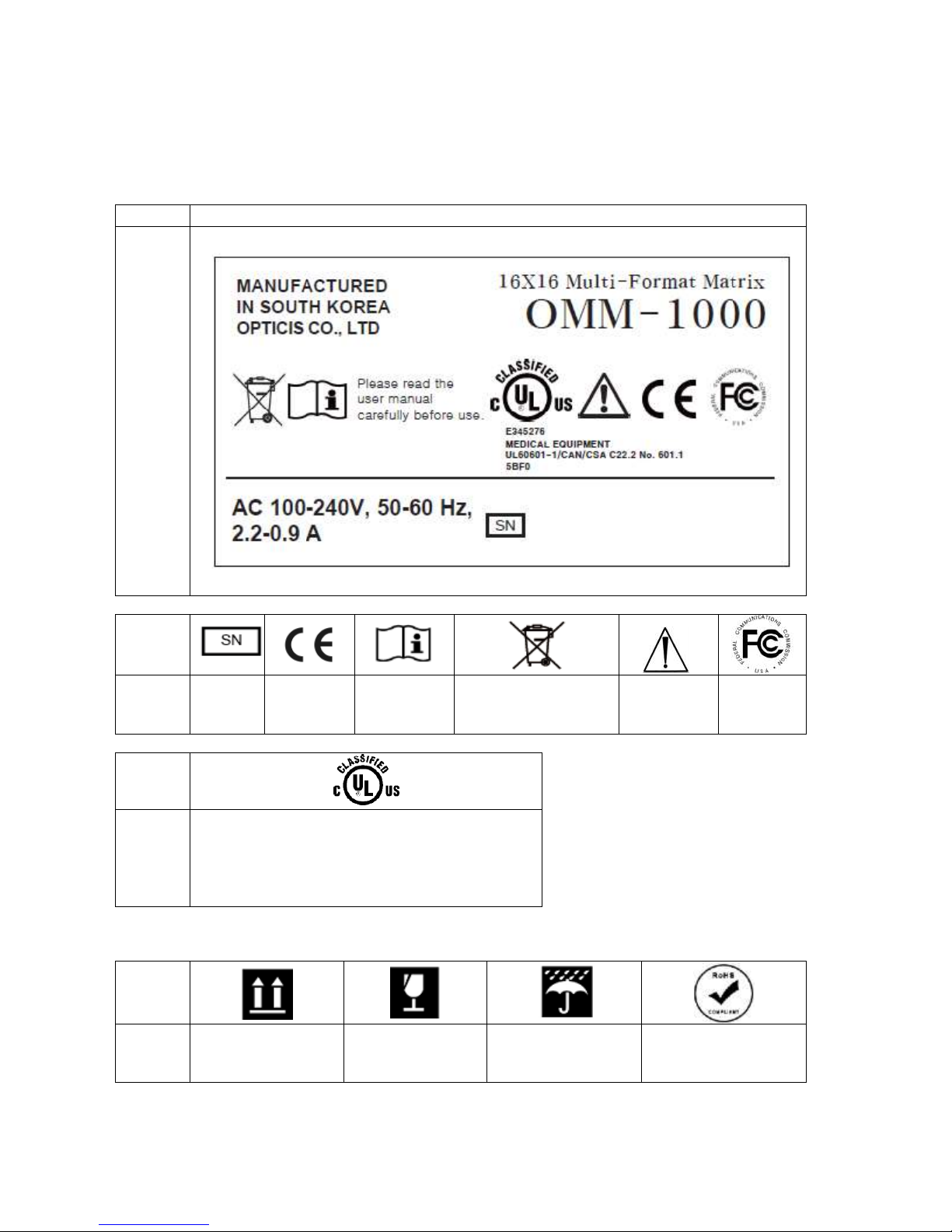
Chapter 14. Symbol Definitions
No
Product Label
1-a
Symbol
Remark
Serial
number
CE
certificate
Consult User
manual
Dispose of Old
Electrical & Electronic
Equipment caution
Refer to
instruction
use
FCC
certificate
Symbol
Remark
MEDICAL EQUIPMENT
WITH RESPECT TO ELECTRIC SHOCK, FIRE, AND
MECHANICAL HAZARDS ONLY
IN ACCORDANCE WITH UL60601-1/CAN/CSA
C22.2 NO. 601.1
5BF0
Symbol
Remark
Loading direction
Fragile caution
Wet caution
RoHS certificate
- Box Symbol
Page 49

49
Opticis Locations
HQ
16Fl. Kins Tower, 8 Seongnam-daero, 331 beon-gil,
Bundang-gu,
Seongnam-si, Gyeonggi-o, 463-844
Rep. of KOREA
Tel: +82 (31) 719-8033
Fax: +82 (31) 719-8032
Factory
#501 Byoksan Technopia, 560,
Dunchon-daero,
Jungwon-gu,
Seongnam-si,Gyeonggi-do, 462-716
Rep. of KOREA
Tel: +82 (31) 737-8033
Fax: +82 (31) 737-8039
For order support, please contact your Distributor or Reseller.
For technical support, visit Opticis web site, www.opticis.com or contact [email protected]
 Loading...