

Optics M1-201DA-TR User Manual
User’s Manual
(For M1-201DA-TR)
Doc No. : OE-D150102-201DA / Rev1.4
Stretch DVITM
Manual Contents
__________________________________________
Manual Contents 1-0
Welcome! Product Description 1-1
System Requirements for Setup 1-2
Installation 1-3
Self-EDID Programming Procedure 1-4
Troubleshooting, Maintenance, Technical Support 1-5
Product Specifications 1-6
Warranty Information 1-7
Regulatory Statements 1-8
Pictorials
Figure 1 – Schematic Connection Diagram of
Optical DVI Extension Modules 1-1
Figure 2 – Connection of power adapter to the
transmitter 1-3
Figure 3 – Connection of power adapter to the
receiver 1-3
Figure 4 – Connection of optical fiber 1-4
Figure 5 – Connection of the transmitter to DVI source 1-4
Figure 6 – Connection of the transmitter to the display 1-4
Figure 7 – Position of EDID-PRGM. button and Self
EDID LED 1-5
1- 0 Manual Contents
Welcome!
Congratulations on your purchase of the Stretch DVITM M1-201DA-TR
Optical DVI (Digital Visual Interface) Extension Module. This manual contains
information that will assist you in installing and operating the product.
Product Description
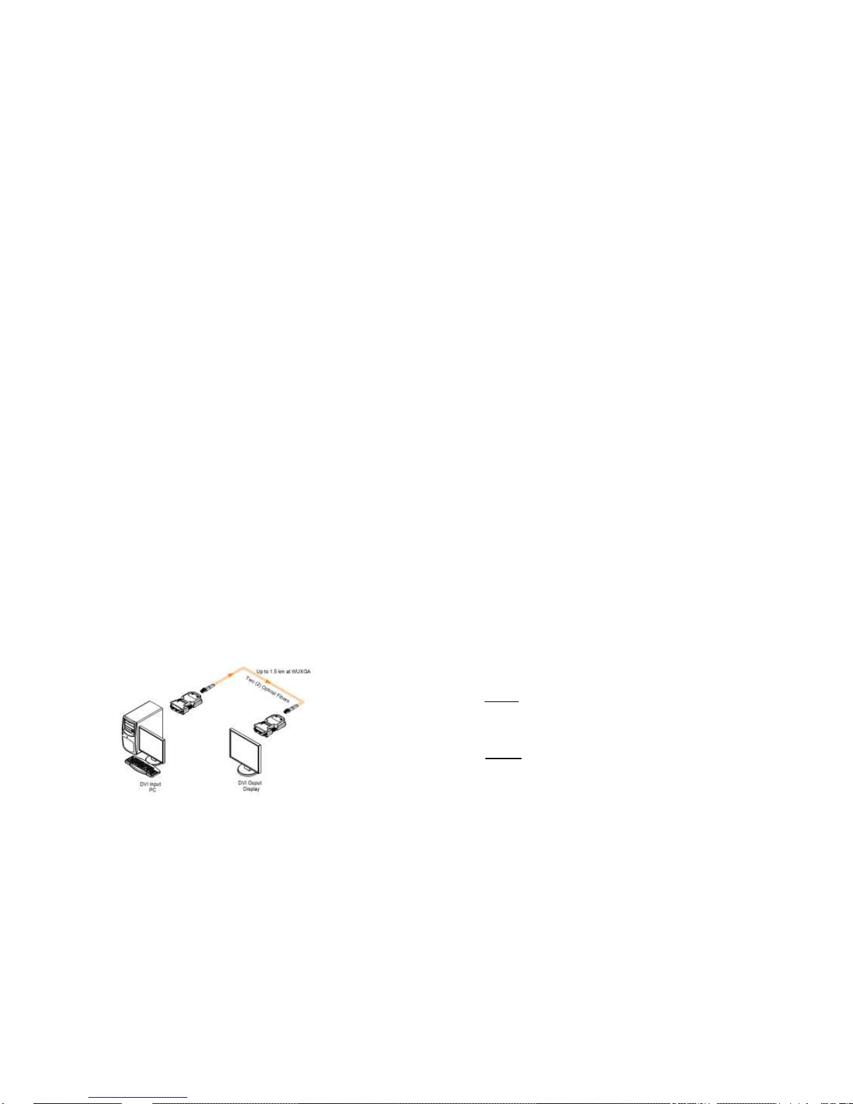
The M1-201DA-TR optical DVI module transmits four (4) optical data, Red,
Green, Blue and clock and can be extended up to 500meters (1,640ft) over
two LC single-mode fiber at 2K resolution at 60Hz or 1500 meters (4,920ft)
over two LC multi or single-mode fiber at WUXGA (1920x1200) at 60Hz
vertical refresh rate. The EDID (Extended Display Identification Data) in a
display can be read and restored by just plugging once transmitter to the
display. This Self-EDID programming feature makes the installation of M1201DA-TR more easy and flexile at any variable resolution display systems.
For your convenience, UXGA EDID would have been done before shipment
as a default.
Shipping Group
M1-201DA-TR Optical DVI Extension Module: One (1) pair
DC power adapter: Two (2) units
User’s Manual
Option Product: Duplex LC Patch Cord (Single or Multi-mode fiber).
Figure 1 – Schematic Connection Diagram of Optical DVI Extension Modules
1-1 Welcome, Product Description
System Requirements for Setup
Hardware requirements
You have to have a DVI graphic controller or card having a DVI
port in your PC, SUN or Mac systems. It should support the
maximum graphic resolution feature of displays to be connected.
No special requirements for memory size, CPU speed and
chipsets, if you’ve already properly installed your DVI graphic
controllers or cards.
Software requirements
No special restrictions, if you’ve already properly installed your
DVI graphic controller in your OS.
AC/DC Power Adapter Technical Advisory
The transmitter (Tx) module of M1-201DA-TR is designed for power
protection circuit from conflict of power supply between the external
DC power adapter and your graphic card through the DVI pin. It offers
an option of whether to use an AC/DC power adapter depending on
power supply capability of the graphic card through the +5V pin, you
are using.
However, the receiver (Rx) module should be supplied by an AC/DC
power adapter.
Note 1: In general, most of laptops or desktop PCs with PCI Express
graphic card require using an AC/DC power adapter for the transmitter
module.
Note 2: If you use laptop or Desktop PC with PCI Express graphic card,
we recommend using 5V power adapter for the transmitter.
1-2 System Requirements for Setup
 Loading...