

Page 1
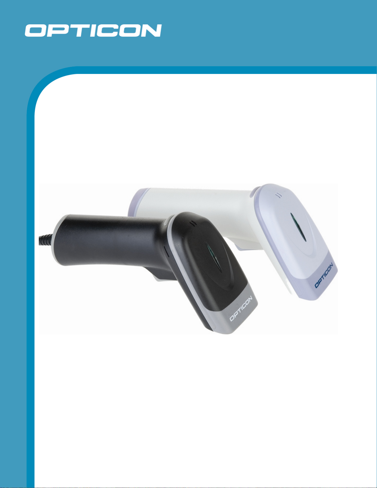
Handheld Laser Barcode Scanner
OPL 7836
The OPL 7836 is a handheld laser barcode scanner.
Specifications Manual
Page 2

All information subject to change without notice.
Document History
Opticon
OPL 7836
Specifications Manual
Model Number:
Edition:
Date:
OPL 7836
2A
2007-02-01
Specification Number:
Original Spec Number:
SS06100
SS06078
Copyright 2007 Opticon. All rights reserved.
This manual may not, in whole or in part, be copied, photocopied, reproduced, translated or converted to any electronic or
machine readable form without prior written consent of Opticon.
Limited Warranty and Disclaimers
PLEASE READ THIS MANUAL CAREFULLY BEFORE INSTALLING OR USING THE
PRODUCT.
Serial Number
A serial number appears on all Opticon products. This official registration number is directly related to the device
purchased. Do not remove the serial number from your Opticon device. Removing the serial number voids the warranty.
Warranty
Unless otherwise agreed in a written contract, all Opticon products are warranted against defects in materials and
workmanship for two years after purchase. Opticon will repair or, at its option, replace products that are defective in
materials or workmanship with proper use during the warranty period. Opticon is not liable for damages caused by
modifications made by a customer. In such cases, standard repair charges will apply. If a product is returned under
warranty and no defect is found, standard repair charges will apply. Opticon assumes no liability for any direct, indirect,
consequential or incidental damages arising out of use or inability to use both the hardware and software, even if Opticon
has been informed about the possibility of such damages.
Packaging
The packing materials are recyclable. We recommend that you save all packing material to use should you need to
transport your scanner or send it for service. Damage caused by improper packaging during shipment is not covered by
the warranty.
Trademarks
Trademarks used are the property of their respective owners.
Opticon Inc. and Opticon Sensors Europe B.V. are wholly owned subsidiaries of OPTOELECTRONICS Co., Ltd., 12-17,
Tsukagoshi 4-chome, Warabi-shi, Saitama, Japan 335-0002. TEL +81-(0) 48-446-1183; FAX +81-(0) 48-446-1184
SUPPORT
USA Europe
Phone: 800-636-0090
Web: www.opticonusa.com Web: www.opticon.com
2
Page 3

Opticon
OPL 7836
Specifications Manual
Contents
1. Abstract....................................................................................................................................... 7
2. Overview...................................................................................................................................... 7
3. Physical Features....................................................................................................................... 8
3.1. Dimensions ......................................................................................................................... 8
3.2. Weight ................................................................................................................................. 8
4. Environmental Specifications ...................................................................................................8
4.1. Operating Temperature and Humidity................................................................................. 8
4.2. Storage Temperature and Humidity .................................................................................... 8
4.3. Ambient Light Immunity....................................................................................................... 8
5. Electrical Specifications ............................................................................................................ 9
5.1. Electrical Characteristics..................................................................................................... 9
6. Optical Specifications................................................................................................................ 9
6.1. Laser Scan Specifications................................................................................................... 9
6.1.1. Tilt of Laser Scan Line ...............................................................................................................9
6.1.2. Curvature of Scan ....................................................................................................................10
7. Technical Specifications.......................................................................................................... 10
7.1. Print Contrast Signal (PCS) .............................................................................................. 10
7.2. Minimum Resolution.......................................................................................................... 10
7.3. Scan Area and Resolution ................................................................................................ 11
7.3.1. Depth of Field...........................................................................................................................11
7.4. Pitch, Skew, and Tilt.......................................................................................................... 12
7.4.1. Pitch Angle ...............................................................................................................................12
7.4.2. Skew Angle and Dead Zone ....................................................................................................13
7.4.3. Tilt Angle ..................................................................................................................................14
7.5. Curvature .......................................................................................................................... 15
8. Interface Specifications ...........................................................................................................16
8.1. RS-232C Interface ............................................................................................................ 16
8.1.1. Settings and Communication ...................................................................................................16
8.1.2. Signal Level..............................................................................................................................16
8.1.3. Pin Assignment ........................................................................................................................16
8.1.4. Interface Circuit ........................................................................................................................17
8.1.5. Character Format .....................................................................................................................17
3
Page 4

Opticon
OPL 7836
Specifications Manual
Communication Format............................................................................................................17
8.1.6.
8.1.7. Communication Control ...........................................................................................................18
8.2. USB Interface.................................................................................................................... 23
8.2.1. Settings ....................................................................................................................................23
8.2.2. Interface Circuit ........................................................................................................................23
8.3. DOS/V Wedge Interface.................................................................................................... 23
8.3.1. Settings ....................................................................................................................................23
9. Cable and Connector ............................................................................................................... 24
9.1. RS-232C Cable ................................................................................................................. 24
9.2. USB Cable ........................................................................................................................ 24
9.2.1. Connector (USB interface) .......................................................................................................25
9.3. Wedge Cable .................................................................................................................... 26
9.3.1. Connector (Wedge interface)...................................................................................................26
9.4. Connector Specification (for scanner)............................................................................... 27
10. Default Settings........................................................................................................................ 28
10.1. Set Default Interface ......................................................................................................... 28
10.2. Default Settings 1: Readable Codes ................................................................................. 29
10.3. Default Settings 2: Read Options, Trigger, Buzzer ........................................................... 31
11. Serial Number and Labeling.................................................................................................... 32
12. Packaging Specifications........................................................................................................32
12.1. Individual Packaging Specification .................................................................................... 32
12.2. Collective Packaging Specification ................................................................................... 32
13. Durability................................................................................................................................... 33
13.1. Electrical Noise ................................................................................................................. 33
13.2. Static Electricity ................................................................................................................. 33
13.3. Shock ................................................................................................................................ 34
13.3.1. Drop Test (without packaging).................................................................................................34
13.3.2. Drop Test (with individual packaging)......................................................................................34
13.4. Vibration ............................................................................................................................ 34
13.4.1. Vibration Strength (without packaging)....................................................................................34
13.4.2. Vibration Strength (individual packaging) ................................................................................34
13.5. Dust and Drip Proof........................................................................................................... 35
13.6. Cable Strength ..................................................................................................................35
13.7. Cable Bending Test........................................................................................................... 35
4
Page 5

Opticon
OPL 7836
Specifications Manual
14. Reliability................................................................................................................................... 36
15. Trigger and Read Options ....................................................................................................... 36
15.1. Auto Trigger Options ......................................................................................................... 36
15.1.1. Auto Trigger Sensor.................................................................................................................36
15.2. Auto Trigger Settings ........................................................................................................ 37
15.2.1. Enable/Disable Settings...........................................................................................................37
16. Regulatory Compliance ...........................................................................................................38
16.1. Laser Safety ...................................................................................................................... 38
16.2. Product Safety................................................................................................................... 38
16.3. EMC .................................................................................................................................. 38
16.4. RoHS................................................................................................................................. 38
17. Safety......................................................................................................................................... 39
17.1. Shock ................................................................................................................................ 39
17.2. Temperature Conditions.................................................................................................... 39
17.3. Foreign Materials .............................................................................................................. 39
17.4. Other ................................................................................................................................. 39
18. Mechanical Drawing.................................................................................................................40
Table of Figures
Figure 1:Laser scan tilt and curvature ........................................................................................ 10
Figure 2: The depth of a decoding field measured from the edge of the scanner. ......................11
Figure 3: Pitch angle................................................................................................................... 12
Figure 4: Skew angle and dead zone ......................................................................................... 13
Figure 5: Tilt angle...................................................................................................................... 14
Figure 6: Curvature..................................................................................................................... 15
Figure 7: Interface circuit ............................................................................................................ 17
Figure 8:Character format (same for both sending and receiving) ............................................. 17
Figure 9: Communication format ................................................................................................ 17
Figure 10: No handshaking ........................................................................................................ 18
Figure 11: Busy/Ready communication ...................................................................................... 19
Figure 12: Cannot receive command ......................................................................................... 19
Figure 13: Signal timing.............................................................................................................. 20
Figure 14: Modem transmit data................................................................................................. 20
Figure 15: ACK/NAK................................................................................................................... 21
Figure 16: ACK/NAK—No response........................................................................................... 22
Figure 17: Interface circuit .......................................................................................................... 23
Figure 18: RS-232C cable .......................................................................................................... 24
Figure 19: USB cable ................................................................................................................. 24
Figure 20: USB "A" connector ....................................................................................................25
5
Page 6

Opticon
OPL 7836
Specifications Manual
Figure 21: WEDGE cable ........................................................................................................... 26
Figure 22: Front view.................................................................................................................. 26
Figure 23: Front view.................................................................................................................. 27
Figure 24: Serial number diagram .............................................................................................. 32
Figure 25: Caution label ............................................................................................................. 32
Figure 26: Drop test.................................................................................................................... 34
Figure 27: Cable bending test .................................................................................................... 35
Figure 28: Mechanical drawing...................................................................................................40
6
Page 7

Specifications Manual
1. Abstract
This manual provides specifications for the OPL 7836 barcode scanner.
2. Overview
The OPL 7836 is a handheld laser barcode scanner.
The OPL 7836 enhances visibility by using a short-wavelength red laser beam when scanning
lines.
Supported symbologies:
Linear (1D) Postal 2D
JAN/UPC/EAN, incl. add-on Chinese Post Composite codes
Codabar/NW-7 Korean Postal Authority Code MicroPDF417
Code 11 PDF417
Code 39
Code 93
Code 128
GS1-128 (EAN-128)
GS1 Databar (RSS)
IATA
Industrial 2of5
Interleaved 2of5
ISBN-ISMN-ISSN
Matrix 2of5
MSI/Plessey
S-Code
Telepen
Tri-Optic
UK/Plessey
Opticon
OPL 7836
The OPL 7836 outputs the scanned barcode image via an RS-232C, USB, or WEDGE
interface according to its specification.
The OPL 7836 complies with RoHS.
7
Page 8

3. Physical Features
3.1. Dimensions
W 144.5 x D 113.0 x H 54.3 (mm)
3.2. Weight
100 g max. (excluding cable)
4. Environmental Specifications
4.1. Operating Temperature and Humidity
Temperature: -5 to +50° C
Humidity: 20 to 85% RH
4.2. Storage Temperature and Humidity
Temperature: -20 to +60° C
Opticon
OPL 7836
Specifications Manual
Humidity: 10 to 90% RH
4.3. Ambient Light Immunity
Decoding performance is guaranteed when the range of illumination on a barcode
surface is between zero and the following values:
Incandescent light to 3,000 lx
Fluorescent light to 3,000 lx
Sunlight to 50,000 lx
Conditions
Barcode Sample: OPTOELECTRONICS Test Sample
PCS: 0.9
Resolution: 0.25 mm
Symbology: 9-digit Code-39
Quiet Zone: 10 mm
N/W Ratio: 1:2.5
Distance: 85 mm
Angle: α = 0° β = 15° γ = 0°
Curvature: R = ∞
Power Supply Voltage: 5.0 V
Direct light or specular reflection from a light source should be prevented from entering
the acceptance area.
Note: α, β and γ respectively represent pitch, skew and tilt. Please see section 7 for how
these values are defined.
8
Page 9
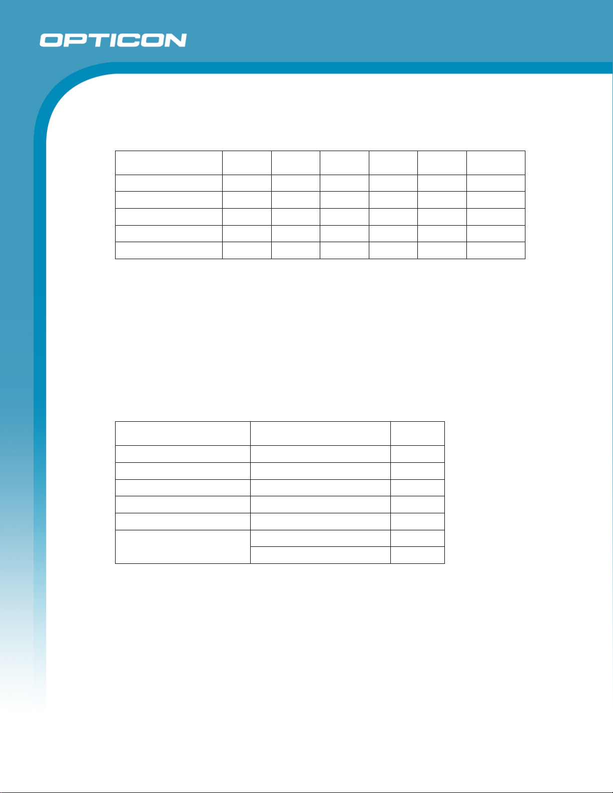
5. Electrical Specifications
5.1. Electrical Characteristics
Parameter Symbol Min Typ Max Unit Remarks
Power supply voltage VDD 4.5 5.0 5.5 V
Operating current IOP - 85 150 mA Buzzer Off
Rush current peak I
Stand-by current I
Startup time TD - 100 - ms
Conditions
• Connect 1Ω resistance to a power supply line in series and measure the
current by the voltage between both ends of resistance.
• Power supply voltage is measured at a connector terminal area.
PEEK
PRE
Opticon
OPL 7836
Specifications Manual
- 450 500 mA
- 35 70 mA
• The current value depends on the interface type and host computer to which
the device is connected.
6. Optical Specifications
6.1. Laser Scan Specifications
Parameter Specification Unit
Light-emitting element Red laser diode —
Emission wavelength 650 ±10 (25° C) nm
Light output 1.0 or less mW
Scanning method Bi-directional scanning —
Scanning speed 100 ±20 scans/s
Notes:
Refer to chapter 15, “Trigger and Read Options,” to read about the scan modes.
Refer to chapter 7, “Technical Specifications,” to read about scanning performance.
Scan angle: 54 ±5 ° Scan angle
Read angle: 44 (Min) °
6.1.1.
Tilt of Laser Scan Line
Maximum tilt between both ends of a laser scan line.
Less than 1.2° upward tilt from the scan origin.
Maximum of 3.1 mm when measured at the point 150 mm away from the scan
origin. (Measurement was done from the center of the scan line.
9
Page 10
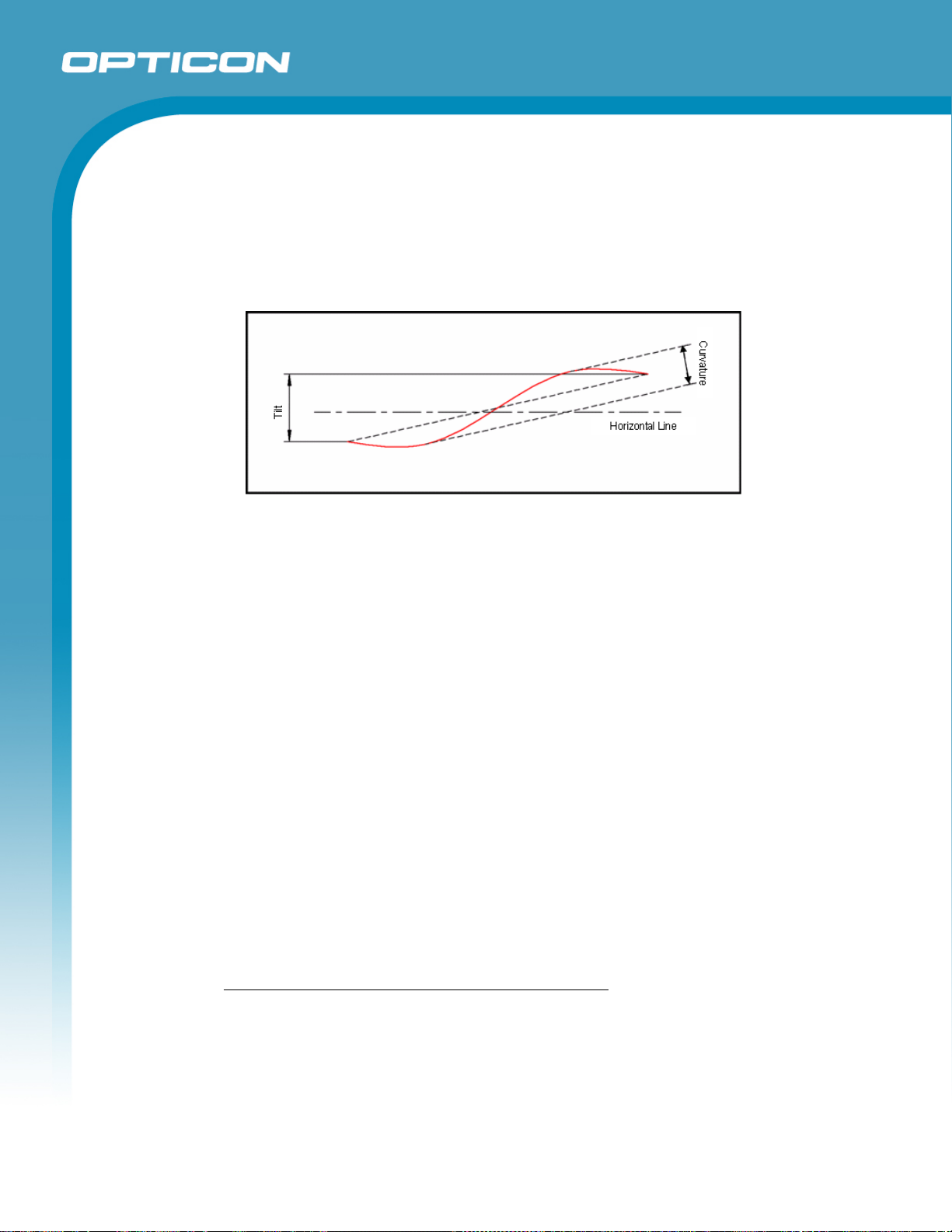
6.1.2. Curvature of Scan
Maximum gap between the straight line connecting both ends of the laser scan
line and the actual laser scan line.
Less than 1.27° curvature from the scan origin.
Maximum of 3.3 mm when measured at the point 150 mm away from scan origin.
(Measured from the center of the scan line.)
Figure 1:Laser scan tilt and curvature
Opticon
OPL 7836
Specifications Manual
7. Technical Specifications
The conditions for technical specifications are as follows, unless otherwise specified in each
section.
Conditions
Ambient temperature
and humidity:
Ambient light: 500 to 900 lx
Background: Barcode = black
Power supply voltage: 5.0 V
Decoding test: Approve the performance when decoding is successful in all ten tests.
7.1. Print Contrast Signal (PCS)
0.45 or higher (over 70% of reflectivity of space and quiet zone).
Reflectance of white bar-Reflectance of black bar
PCS=
Reflectance of white bar
Room temperature (5 to 35º C)
Room humidity (45% to 85% RH)
Space = white
Margin = white
Background of label = black
(Decoding is deemed successful when completed in 0.5 seconds or less.)
Scanning performance may decline if dirt or scratches mar the optical window. Keep the
optical window clean.
7.2. Minimum Resolution
0.127 mm
10
Page 11
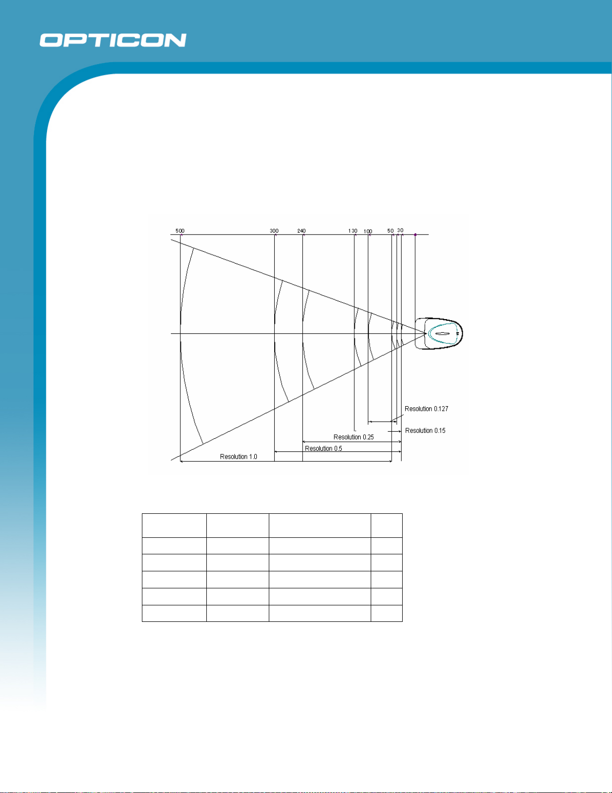
7.3. Scan Area and Resolution
7.3.1. Depth of Field
The depth of field is measured from the edge of the scanner. The scanning range
is within the circular arc centered on the scan origin.
X direction: Depth of field
Y direction: Laser scan widths within the depth of field
Opticon
OPL 7836
Specifications Manual
Figure 2: The depth of a decoding field measured from the edge of the scanner.
Symbology Resolution Depth of field (mm) PCS
Code 39 1.0 mm 50–500 0.9
Code 39 0.5 mm 30–300 0.9
Code 39 0.25 mm 30–240 0.9
Code 39 0.15 mm 30–130 0.9
Code 39 0.127 mm 40–100 0.9
Conditions
Barcode Sample: OPTOELECTRONICS Test Sample
N/W ratio: 1:2.5
Angle: α = 0°, β = 15°, γ = 0°
Curvature: R = ∞
11
Page 12
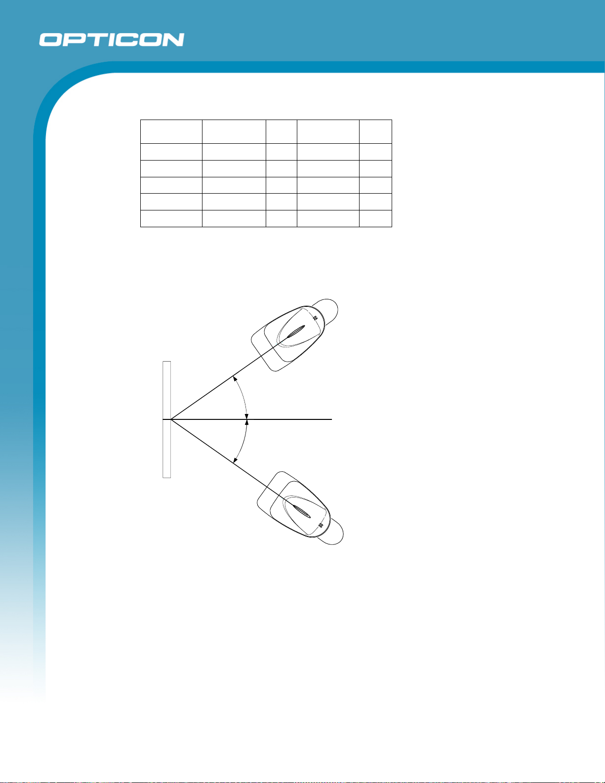
Resolution Symbology PCS Quiet Zone Digit
1.0 mm Code 39 0.9 25 mm 1
0.5 mm Code 39 0.9 18 mm 3
0.25 mm Code 39 0.9 10 mm 8
0.15 mm Code 39 0.9 7 mm 10
0.127 Code 39 0.9 5 mm 4
7.4. Pitch, Skew, and Tilt
7.4.1. Pitch Angle
α = ±35°
Opticon
OPL 7836
Specifications Manual
α=35°
α=35°
Figure 3: Pitch angle
12
Page 13
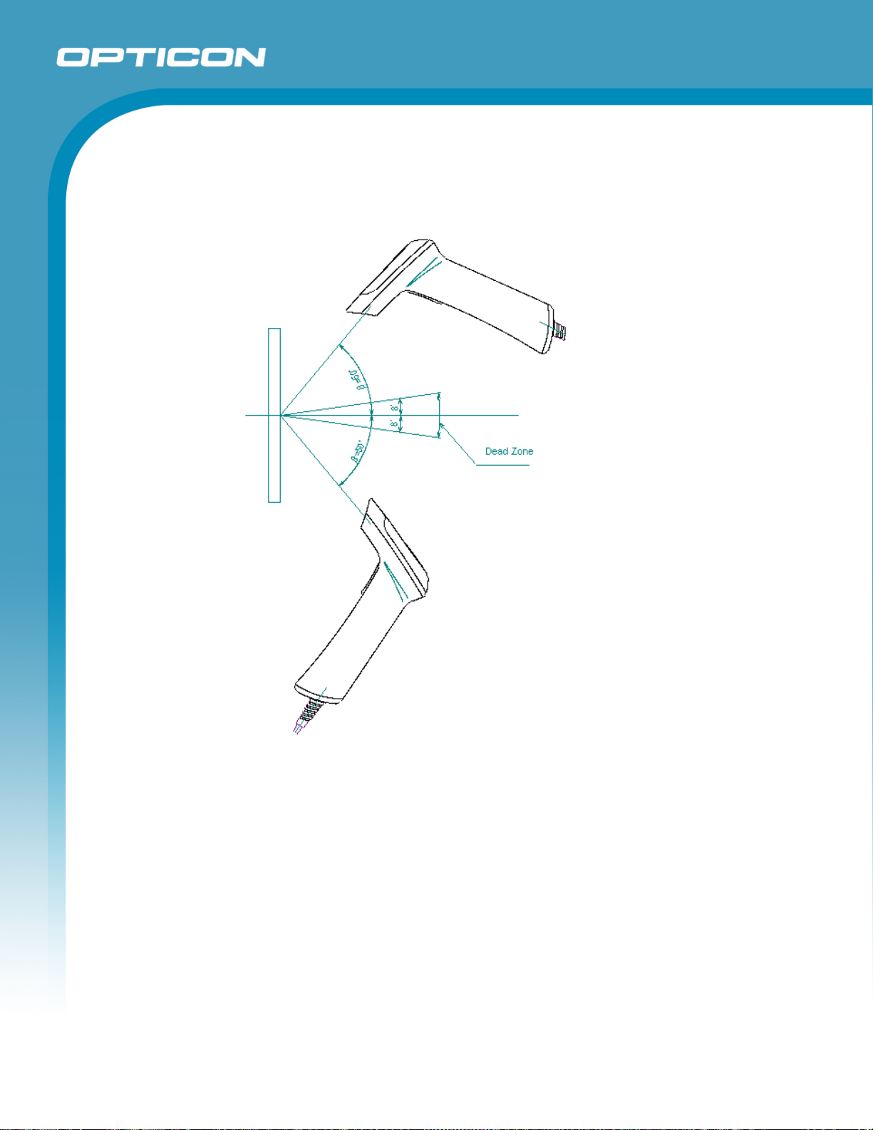
7.4.2. Skew Angle and Dead Zone
β = ±50° (Excluding dead zone)
β = ±8° (There are some areas in which decoding fails due to specular reflection)
Opticon
OPL 7836
Specifications Manual
Figure 4: Skew angle and dead zone
13
Page 14
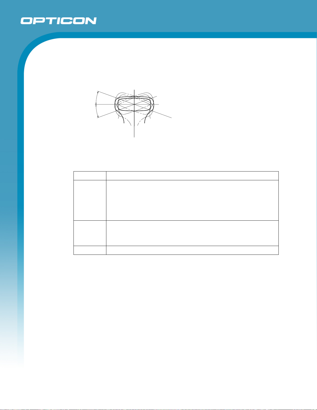
7.4.3. Tilt Angle
γ = ±20°
°
0
2
=
γ
°
0
2
=
γ
Figure 5: Tilt angle
Conditions
Barcode Sample: OPTOELECTRONICS Test Sample
Opticon
OPL 7836
Specifications Manual
Distance: 90 mm from the front edge of the scanner
Label:
Angle:
Curvature: R = ∞
Pitch, Skew Angle, Dead Zone
PCS = 0.9, Resolution = 0.25 mm, Symbology = 9-digit Code-39,
N/W Ratio = 1:2.5
Tilt Angle
PCS = 0.9, Resolution = 0.26 mm, Symbology = 13-digit JAN,
Quiet Zone = 10 mm
At Pitch: Skew angle β = +15°, Tilt angle = 0°
At Tilt angle: Pitch angle α = 0°, Skew angle β = +15°
At Skew angle and dead zone: Pitch angle α = 0°, Tilt angle γ = 0°
14
Page 15
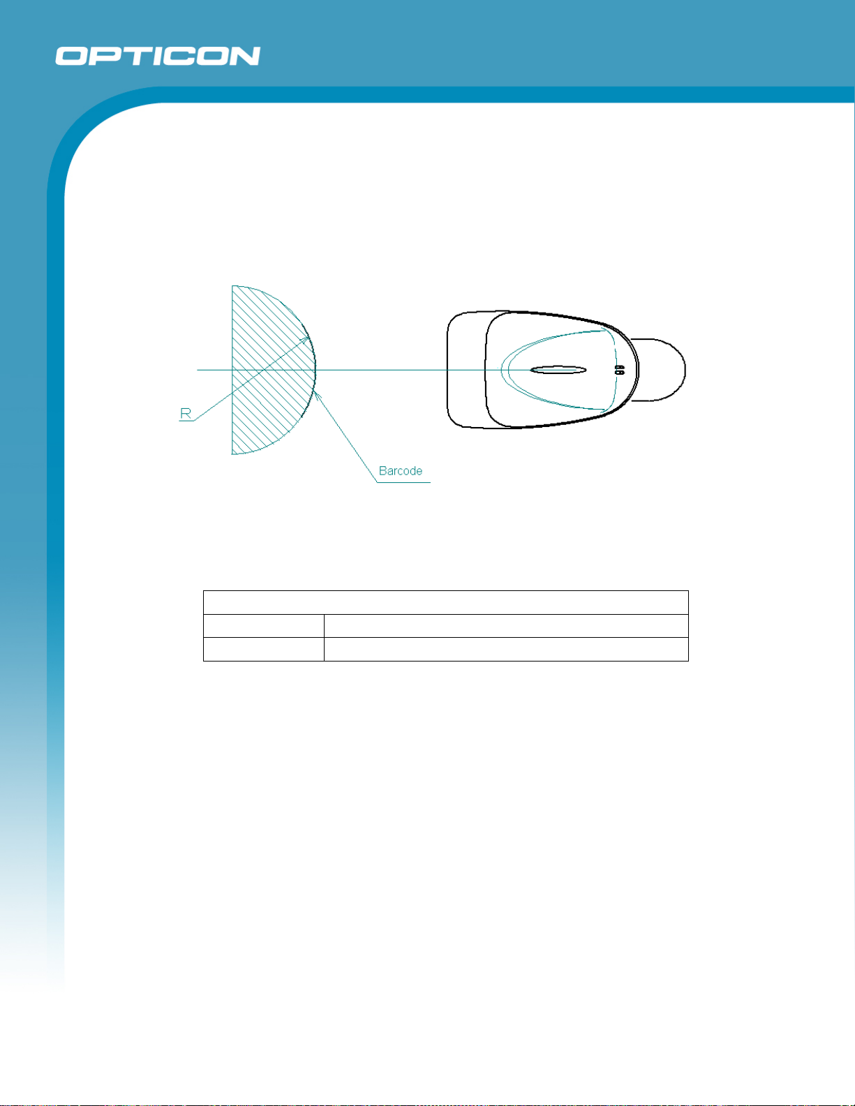
7.5. Curvature
With 8-digit JAN/UPC/EAN barcodes, decoding performance is guaranteed when
R≥15 mm.
With 13-digit JAN/UPC/EAN barcodes, decoding performance is guaranteed when
R≥20 mm.
Opticon
OPL 7836
Specifications Manual
Figure 6: Curvature
Conditions
Barcode Sample: OPTOELECTRONICS Test Sample
PCS = 0.9, Resolution = 0.26 mm, Quiet Zone = 10 mm
Distance: 90 mm from the edge of the scanner
Angle: Skew Angle β = +15°
15
Page 16
8. Interface Specifications
8.1. RS-232C Interface
8.1.1. Settings and Communication
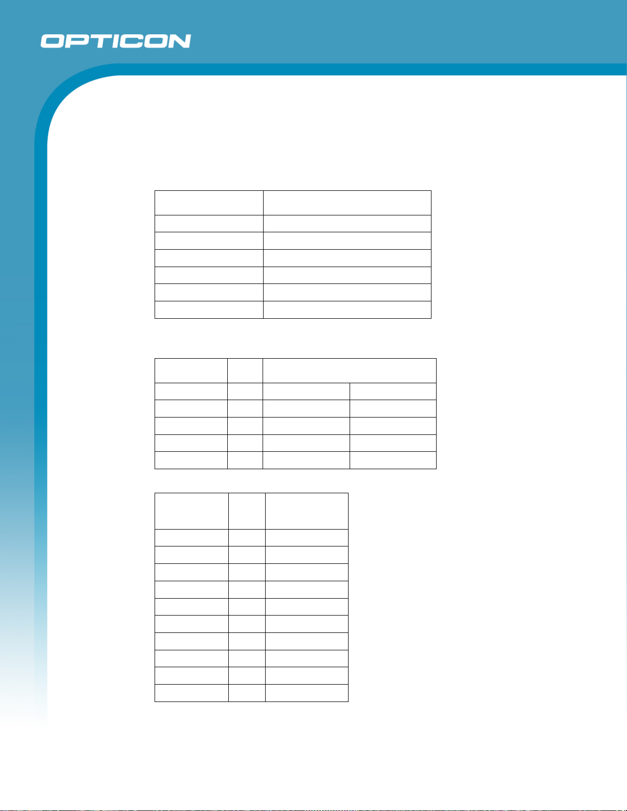
Scan menu bar codes “ZZ” + “U2” + “ZZ” to initialize RS-232 interface.
Item [U2] setting
Baud rate 9600 BPS
Start/stop bits 1 bit
Data bits 8 bits
Parity bits No parity
Handshaking No handshake
CTS waiting time Infinite
You can change the communication condition using the menu barcode.
Opticon
OPL 7836
Specifications Manual
8.1.2.
Signal Level
Signal Name I/O RS-232C Level (V)
Mark/OFF Space/ON
TxD OUT -5 to -15 +5 to +15
RxD IN -3 to -15 +3 to +15
RTS OUT -5 to -15 +5 to +15
CTS IN -3 to -15 +3 to +15
8.1.3. Pin Assignment
Signals Pin
No.
NC 1 No connection
TXD 2
RXD 3
- 4 6 pin and jumper
GND 5
- 6 4 pin and jumper
CTS 7
RTS 8
NC 9 No connection
F.GND Shell Shield
Remarks
Connector: Equipped with external power supply stereo jack (D-sub 9-pin female)
Power supply: Stereo jack
16
Page 17
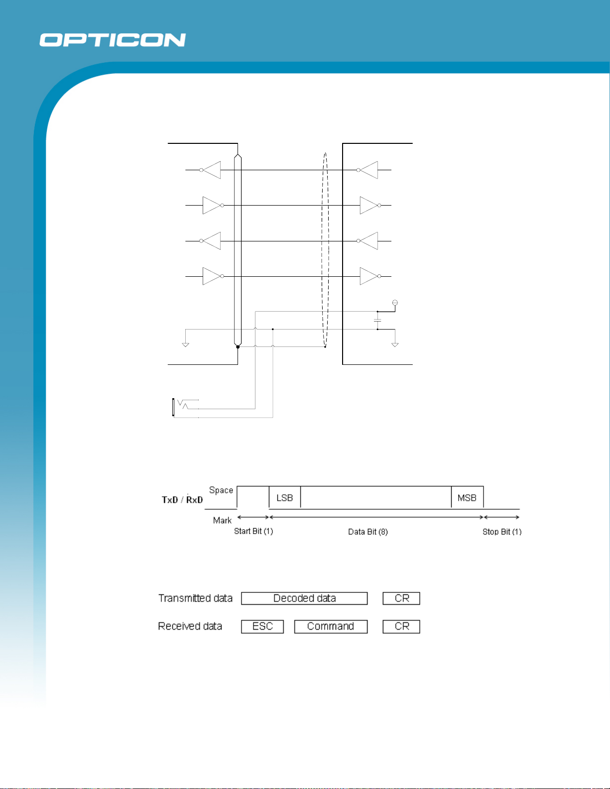
8.1.4. Interface Circuit
Host Computer
ホスト 本機
Opticon
OPL 7836
Specifications Manual
Scanner
DC INPUT
TXD
RXD
RTS
CTS
VCC
GND
F.GND
Figure 7: Interface circuit
(ADM3202 Compatibility Product)
(ADM3202相当品)
8.1.5. Character Format
Figure 8:Character format (same for both sending and receiving)
8.1.6. Communication Format
Figure 9: Communication format
17
Page 18
8.1.7. Communication Control
Select handshaking options using the menu or command listed below.
Handshaking Menu/Command
No handshake P0
BUSY/READY P1
MODEM P2
ACK/NAK P3
ACK/NAK NO RESPONSE P4
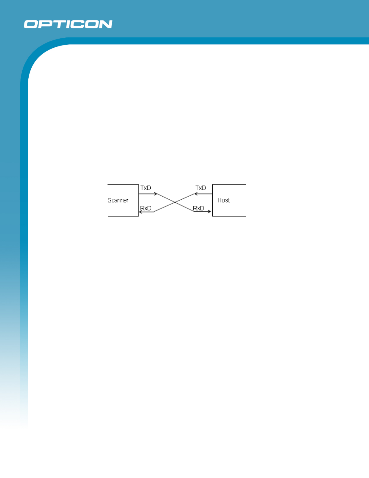
a) No Handshaking
The scanner attempts the communication regardless of the state of the host
computer.
Opticon
OPL 7836
Specifications Manual
Figure 10: No handshaking
18
Page 19
Specifications Manual
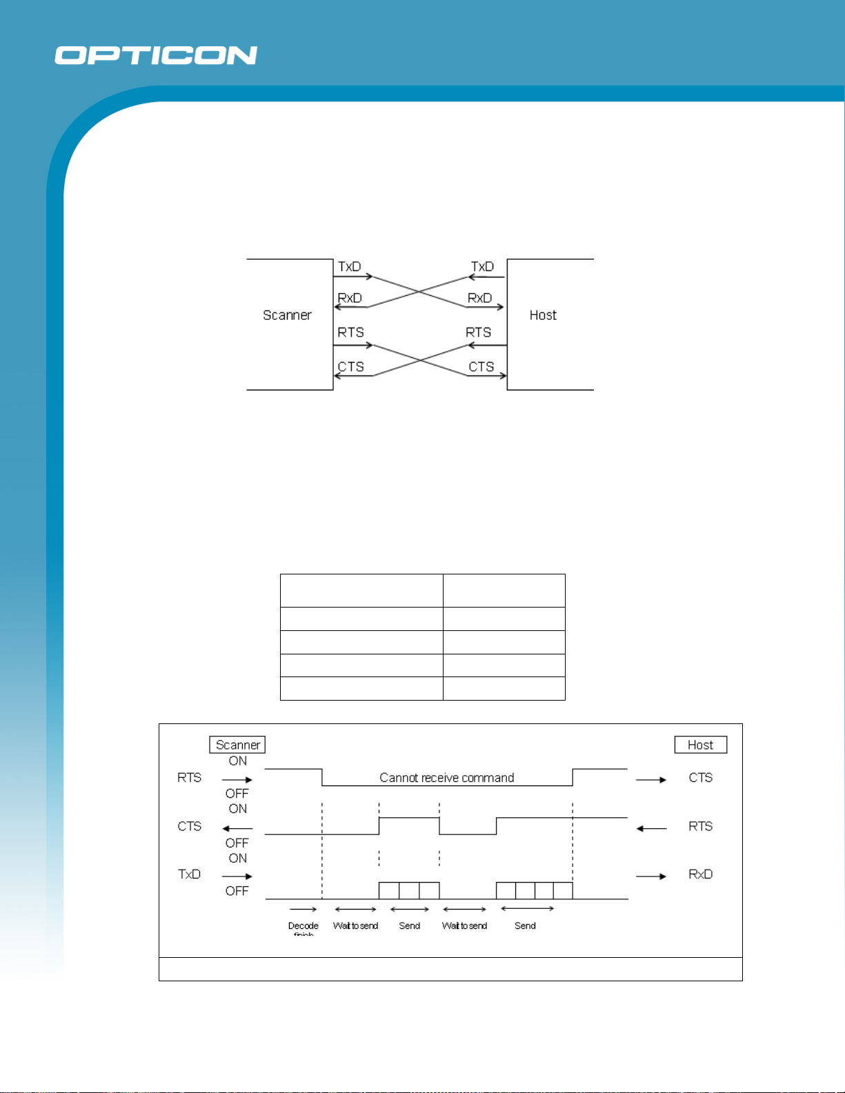
b) BUSY/READY
The scanner and the host computer notify each other of their state and
whether they can receive data with BUSY/READY through an RTS line. They
can communicate state to each other through a CTS line when connected as
in the following figure.
Figure 11: Busy/Ready communication
The scanner stays ON (is able to receive data) except during certain parts of
the process, such as receiving data (buzzer command execution), transmitting
data, and menu processing. The scanner checks the CTS line before
transmitting data. When it is ON, the scanner transmits data. When it is OFF,
the scanner waits for it to turn ON within a set time. The scanner will abort
transmission with an error indication (buzzer) when the CTS line is not ON
within a specified period. The Flow Control time-outs are as follows, and the
default setting is “indefinitely“ (I0).
Opticon
OPL 7836
Flow Control Time Out Menu/Command
Indefinitely I0
100 ms I1
200 ms I2
400 ms I3
Figure 12: Cannot receive command
19
Page 20

Opticon
OPL 7836
Specifications Manual
CTS, T×D signals timing
When the CTS line (RTS signal of the host) is turned OFF while sending a T×D signal,
the scanner transmits one character and waits. When the CTS signal is turned ON while
transmitting a character, the character will be transmitted.
Figure 13: Signal timing
Note: When using loopback (wire connection) for RTS, CTS line of the scanner in this
setting, No handshake is not enabled.
c) MODEM
The scanner turns CS line ON before transmitting data. Other processes are
the same as BUSY/READY.
Figure 14: Modem transmit data
20
Page 21
Specifications Manual
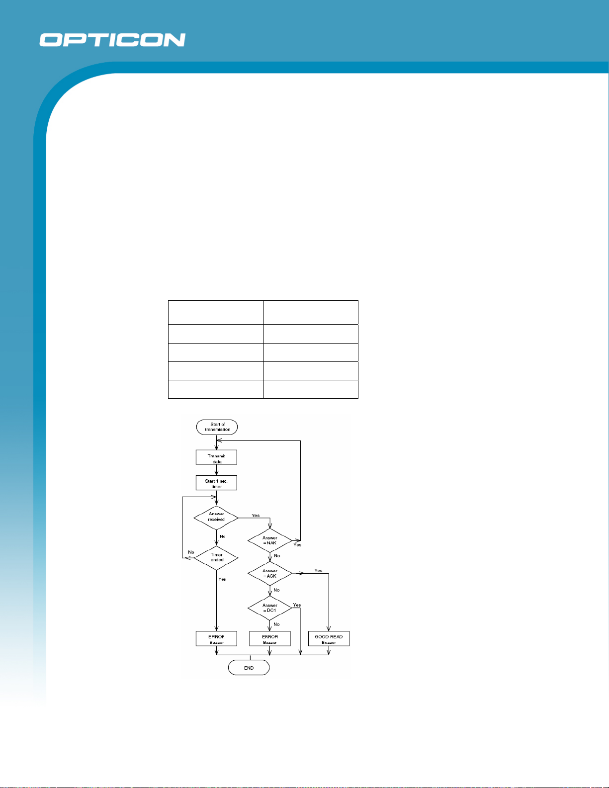
d) ACK/NAK
After data has been transmitted, the scanner expects to receive one of the
following responses from the host:
• ACK response—Action: The scanner completes transmission with the
good-read buzzer and returns to the initial state.
• NAC response—Action: The scanner sends the data again and waits for
the response from the host.
• DC1 response—Action: The scanner returns to waiting for the trigger, if it
has a trigger (the initial state).
• None response—Action: The scanner sounds the error buzzer and returns
to the initial state.
ACK/NAK timeout can be set as follows using the menu or commands.
ACK/NAK timeout Menu / Command
Opticon
OPL 7836
Indefinitely (default)
100 ms
500 ms
1000 ms
XI4
XI5
XI6
XI7
Figure 15: ACK/NAK
21
Page 22
Specifications Manual
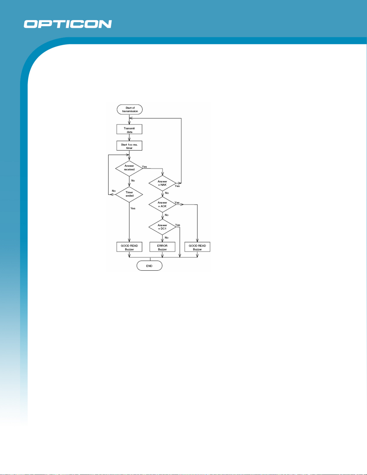
e) ACK/NAK NO RESPONSE
When no response from the host is received within the setting time, the
scanner assumes an ACK response, and returns to the initial state without the
error buzzer. The other actions are the same as ACK/NAK.
Opticon
OPL 7836
Figure 16: ACK/NAK—No response
22
Page 23
8.2. USB Interface
8.2.1. Settings
Scan menu bar code “ZZ”+ “SU”+”ZZ” to set USB interface.
The OPL 7836 utilizes a full-speed USB interface.
Opticon
OPL 7836
Specifications Manual
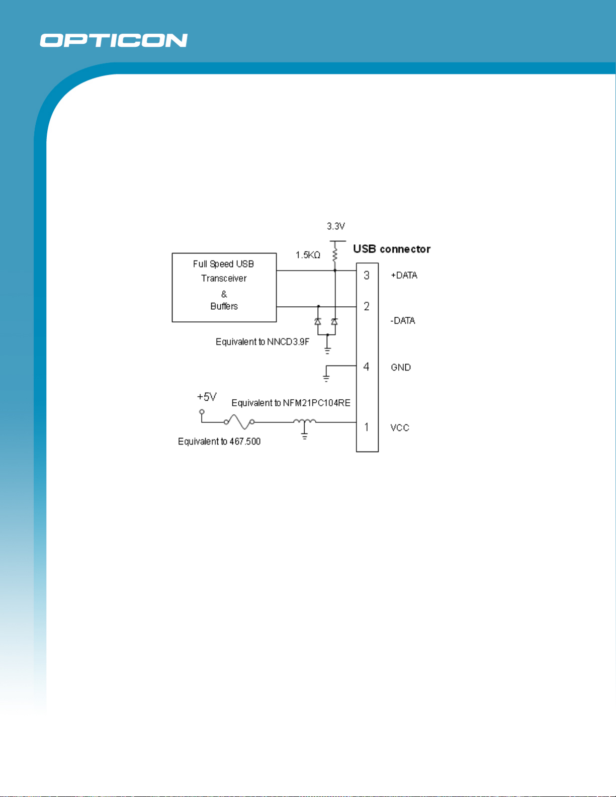
8.2.2.
Interface Circuit
Figure 17: Interface circuit
Do not use the keyboard of the host during data transmission from the scanner to
host. It may cause problems with the data transmission.
8.3. DOS/V Wedge Interface
8.3.1. Settings
a) Desktop type (used in combination with external keyboard)
Set by default; this procedure is only used when settings are changed.
Scan menu bar code “ZZ”+”UB”+”KM”+”ZZ” to set the DOS/V Wedge interface
for desktop type.
b) Notebook type (without external keyboard)
Scan menu bar code “ZZ”+”UB”+”KL”+”ZZ” to set DOS/V Wedge interface for
notebook.
23
Page 24
9. Cable and Connector
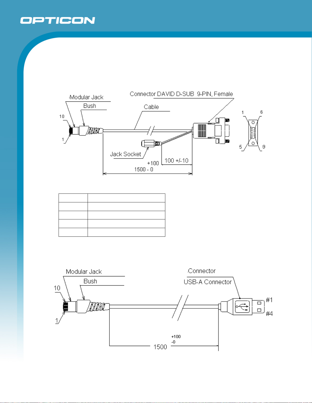
9.1. RS-232C Cable
(Standard specification)
Opticon
OPL 7836
Specifications Manual
Diameter: φ3.8±0.5 mm
9.2. USB Cable
(Standard specification)
Figure 18: RS-232C cable
Type: Straight cable
Length: 1500±50 mm
Cores: 6 insulated wires, 1 conductive wire
Weight: Approximately 40 g
Figure 19: USB cable
24
Page 25
Opticon
OPL 7836
Specifications Manual
Type: Straight cable
Diameter: φ3.8±0.5 mm
Length: 1500±100 mm
Cores: 4 insulated wires, 1 conductive wire
Weight: Approximately 40 g
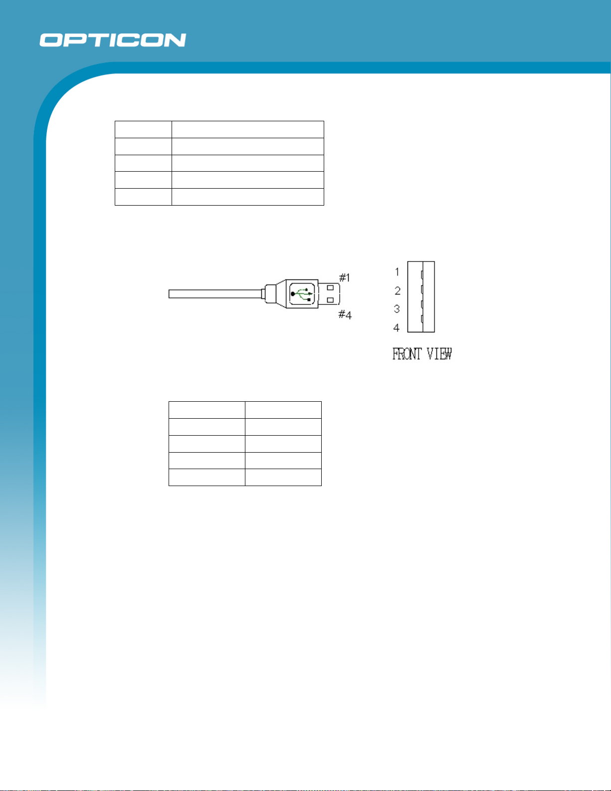
9.2.1. Connector (USB interface)
a) USB "A" connector
Figure 20: USB "A" connector
Contact Number Signal Name
1 VCC
2 -DATA
3 +DATA
4 GND
25
Page 26
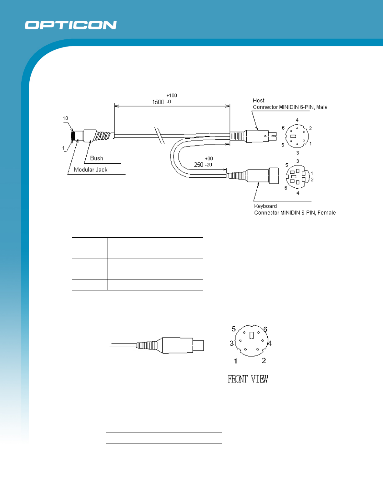
9.3. Wedge Cable
(Standard specification)
Opticon
OPL 7836
Specifications Manual
Figure 21: WEDGE cable
Type: Y cable
Diameter: φ3.8±0.5 mm
Length: 1500±100 mm
Cores: 6 insulated wires, 1 conductive wire
Weight: Approximately 50 g
9.3.1. Connector (Wedge interface)
a) DOS/V HOST Side
Figure 22: Front view
Contact Number Signal Name
1 CPU_DATA
2 KEY_DATA
26
Page 27
Opticon
OPL 7836
Specifications Manual
3 GND
4 VCC
5 CPU_CLK
6 KEY_CLK
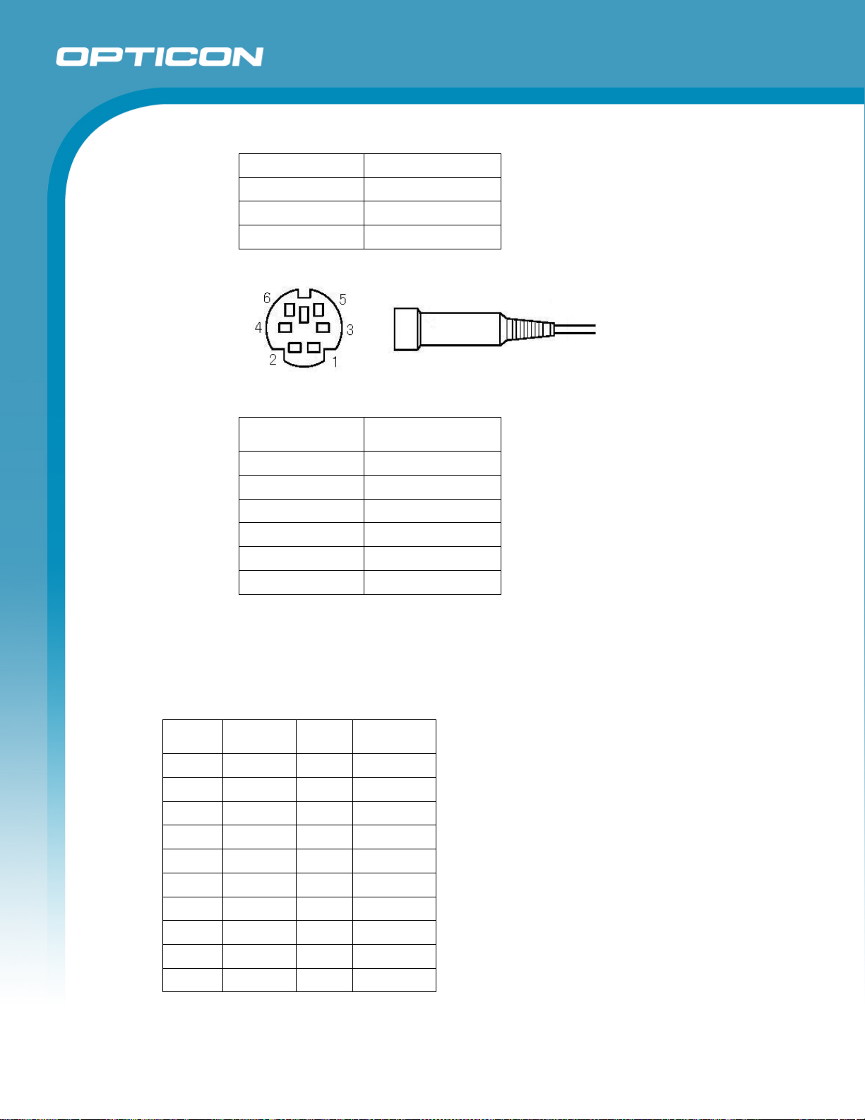
b) DOS/V KEYBOARD Side
Figure 23: Front view
Contact Number Signal Name
1 KEY_DATA
2 OPEN
3 GND
4 VCC
5 KEY_CLK
6 OPEN
Do not use the keyboard of host during data transmission from the scanner to
host. It may cause problems with the data transmission.
9.4. Connector Specification (for scanner)
CN 1 (10-pin)
Pin No RS-232C USB WEDGE
1 RTS - -
2 CTS - -
3 TXD - -
4 RXD - -
5 5V 5V 5V
6 GND GND GND
7 - -DATA KEY_CLK
8 - +DATA KEY_DATA
9 - - CPU_CLK
10 - - CPU_DATA
27
Page 28
10. Default Settings
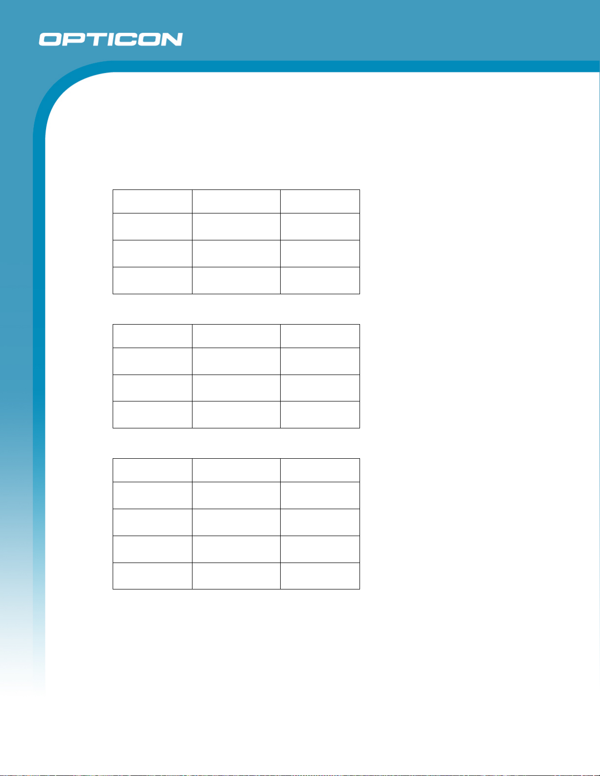
10.1. Set Default Interface
Scan the following menu barcodes to return to the default settings.
RS-232C
Functions Menu labels Menu codes
Opticon
OPL 7836
Specifications Manual
SET
RS-232C
END
USB-HID
Functions Menu labels Menu codes
SET
USB-HID
END
Wedge (with external keyboard)
Functions Menu labels Menu codes
SET
_ZZ_
_U2_
_ZZ_
_ZZ_
_SU_
_ZZ_
_ZZ_
ZZ
U2
ZZ
ZZ
SU
ZZ
ZZ
AT-Wedge
Keyboard layout:
with keyboard
END
_UB_
_KM_
_ZZ_
UB
KM
ZZ
28
Page 29
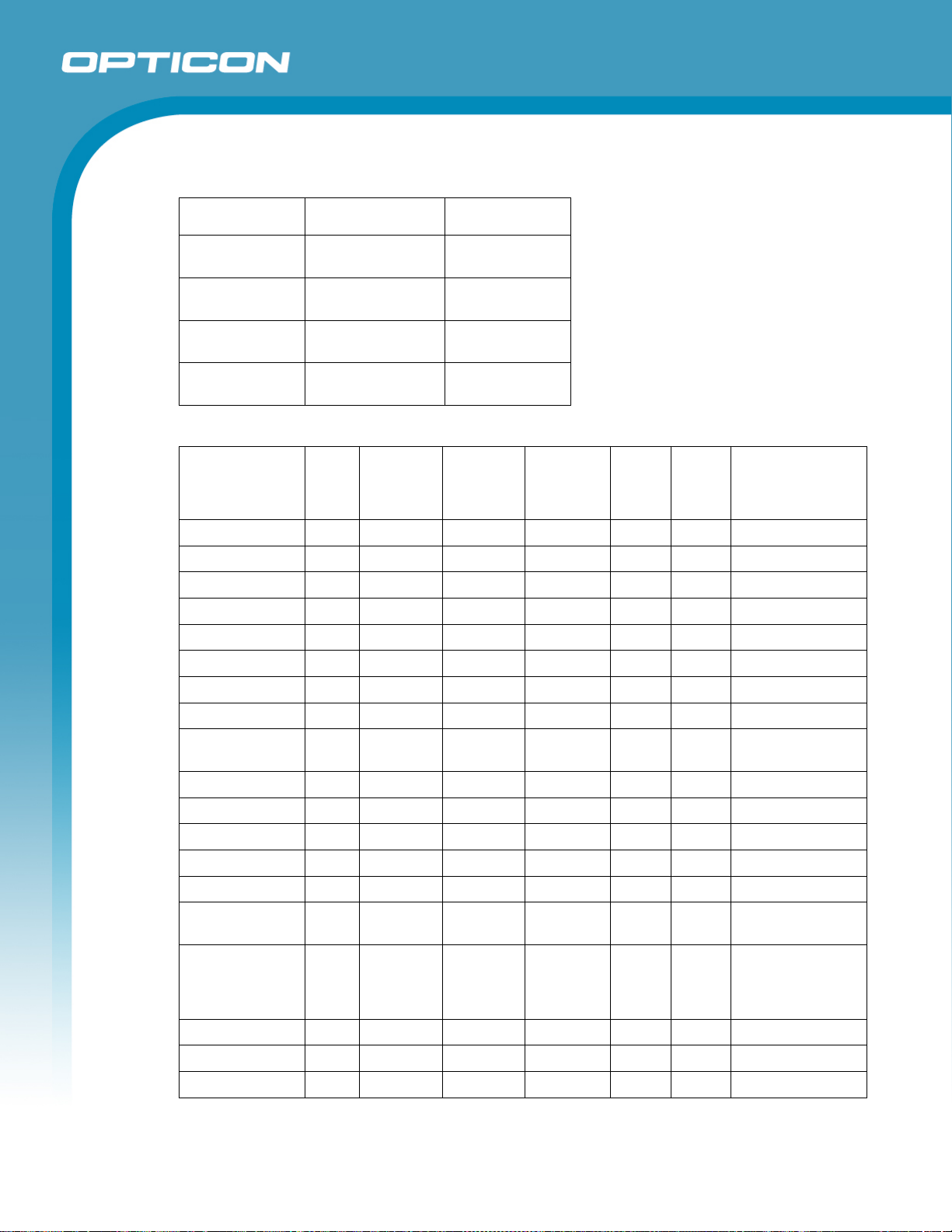
Wedge (without external keyboard)
Functions Menu labels Menu codes
Opticon
OPL 7836
Specifications Manual
SET
AT-Wedge
Keyboard layout:
without keyboard
END
_ZZ_
_UB_
_KL_
_ZZ_
10.2. Default Settings 1: Readable Codes
Symbology Read Transmit
Code
Length
UPC-A
UPC-A Add-on X X
UPC-E
UPC-E Add-on X X
EAN-13
EAN-13 Add-on X X
EAN-8
EAN-8 Add-on X X
Chinese Post
Matrix 2of5
Codabar / NW-7
Code 11 X X X
Code 39
Code 93
Code 128
GS1-128
(EAN/UCC-128)
GS1 DataBar
(RSS) (all, incl.
CC-A/B); Limited/
Expanded
IATA
Industrial2of5
Interleaved2of5
X X
X X X
X X
X
X
X
X
X
X
X X
X X
X
X
X
Transmit
CD
ZZ
UB
KL
ZZ
Calculate
CD
X — CR
X — CR Not transmit ST/SP
X — CR Not transmit ST/SP
X — CR
X — CR
X — CR
Set
Prefix
— CR
— CR
— CR
— CR
— CR
— CR
— CR
— CR
— CR
— CR
— CR
— CR
— CR
Set
Suffix
Other
29
Page 30
Opticon
OPL 7836
Specifications Manual
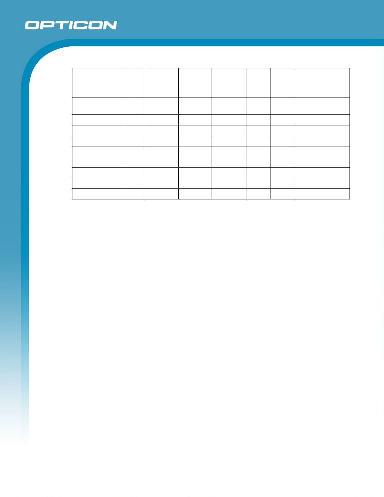
Symbology Read Transmit
Code
Transmit
CD
Calculate
CD
Set
Prefix
Set
Suffix
Other
Length
Korean Postal
Code
Matrix2of5 X X
MicroPDF417 X X — — — CR
PDF417 X X — — — CR
MSI/Plessey
S-Code
Telepen
Trioptic
UK/Plessey
X X X
X CD1 CD1 — CR
X
X X
X — — — CR Not transmit ST/SP
X
X — CR
X — CR
— CR
— CR
— CR
Notes:
In the “Reading” column, “
In the “Transmit code length” column, “
” means “Enable reading” and “X” means “Disable reading.”
” means “Transmit code length” and “X” means
“Do not transmit code length.”
In the “Transmit CD” column, “
” means “Transmit check digit” and “X” means “Do not
transmit check digit.”
In the “Calculate CD” column, “
” means “Calculate check digit” and “X” means “Do not
calculate check digit.”
“— “ means “not supported.”
In the “Prefix” column, “—“ means “there is no prefix setting.”
30
Page 31
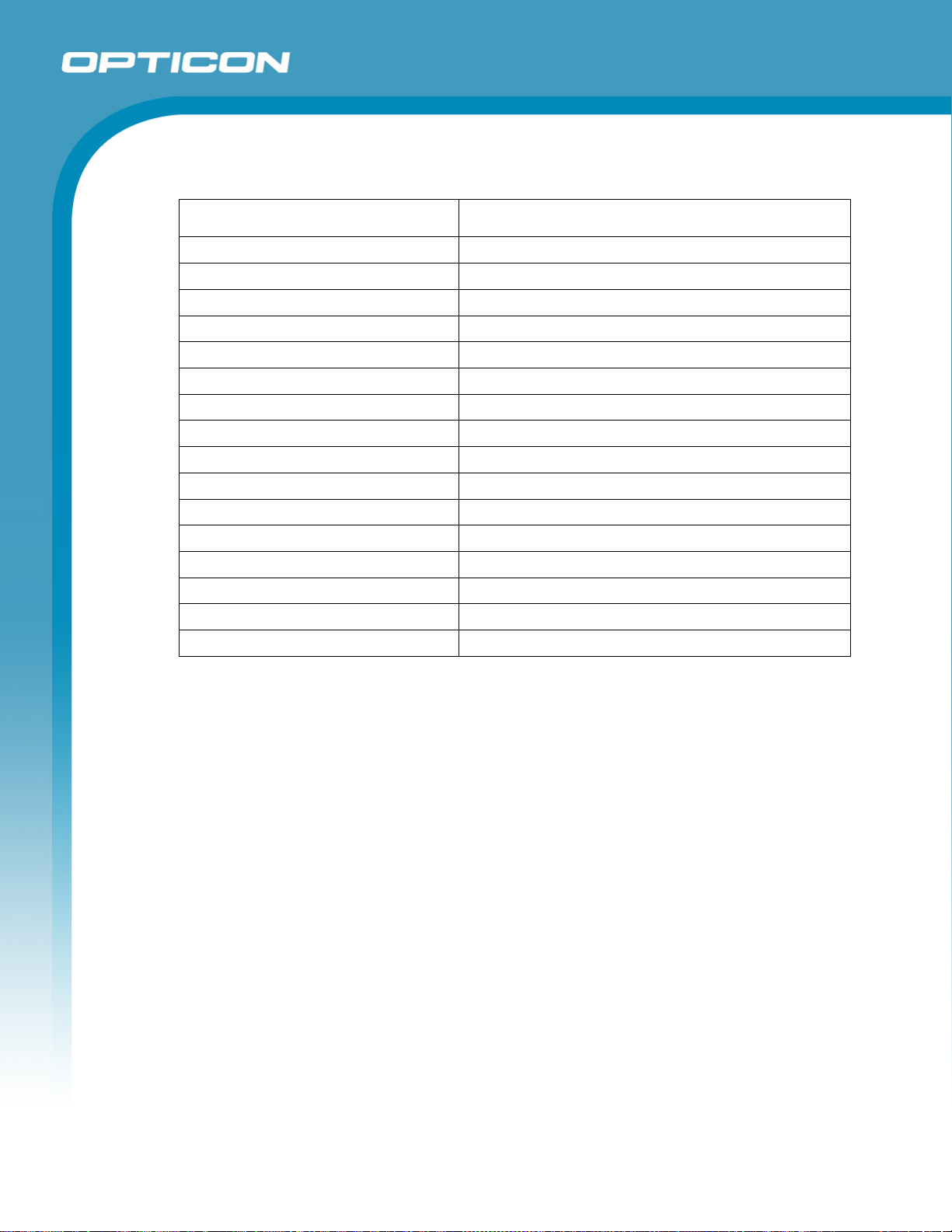
10.3. Default Settings 2: Read Options, Trigger, Buzzer
Item Default Setting
Setting the number of characters Fixed length OFF all codes
Read mode Single read
Multiple read reset time 500 ms
Add-on wait mode 500 ms
Redundancy Read 4 times, redundancy = 3
Trigger switch Enable
Trigger repeat Disable
Auto trigger Disable (refer to the Universal Menu Book for details)
Read time 2 seconds
Margin check Normal
Buzzer duration 50 ms
Buzzer tone Single tone (3 kHz)
Buzzer loudness T1 (Loud)
Buzzer transmission Before transmission
Startup buzzer Enable
Good read LED Indicator duration 200 ms
Opticon
OPL 7836
Specifications Manual
31
Page 32
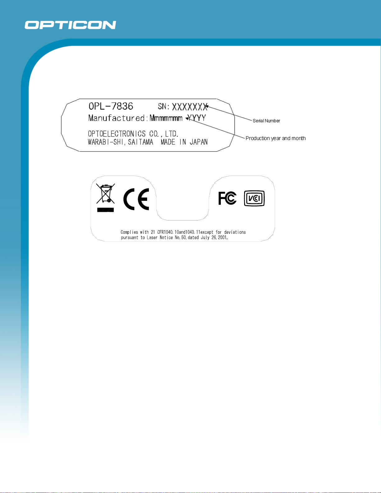
11. Serial Number and Labeling
The serial number is shown below is affixed to the scanner.
Figure 24: Serial number diagram
Opticon
OPL 7836
Specifications Manual
JIS C6802:2005
I EC60825- 1+A2: 2001 CLASS 1 LASER PRODUCT
Figure 25: Caution label
12. Packaging Specifications
12.1. Individual Packaging Specification
Put the scanner in a protective foam bag and place it in an individual packing box.
Size of the package (after assembly: (W) 245 x (D) 110 x (H) 85 mm
12.2. Collective Packaging Specification
Place 50 individual boxes with scanners inside a box.
Note: The “RO” mark labeled on the package tray or package box guarantees that the
applicable product has passed our test of RoHS restrictions compliance (the restriction of
the use of certain hazardous substances in electrical and electronic equipment, 2002/95
EC). However, this document does not have any legal weight in the European Union.
クラス1レーザ製品
32
Page 33
13. Durability
13.1. Electrical Noise
No malfunction occurred when sinusoidal electrical noise (10 Hz–100 kHz, < 0.1 Vp-p)
was added to the power supply line.
Conditions
Barcode Sample: OPTOELECTRONICS Test Sample
PCS 0.9
Resolution 0.25 mm
Symbology 9-digit Code 39
Quiet Zone 10 mm
N/W Ratio 1:2.5
Distance 90 mm
Angle α = 0° β = 15° γ = 0°
Curvature R = ∞
Power Supply Voltage 5.0 V
Opticon
OPL 7836
Specifications Manual
13.2. Static Electricity
Air discharge: 10kV Max (No malfunction)
Measurement environment: Use electrostatic testing device compliant with IEC 61000-4-2
Discharge resistance: 330Ω
Capacitor charging: 150pF
15kV Max (No destruction)
33
Page 34
13.3. Shock
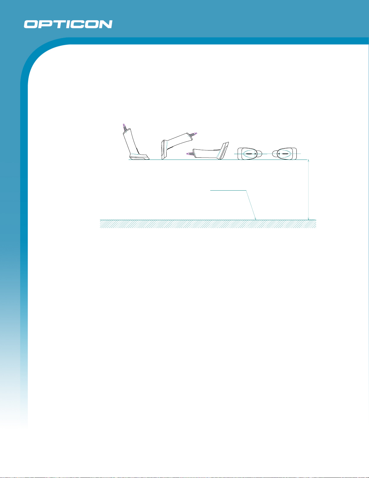
13.3.1. Drop Test (without packaging)
No malfunction occurred after the following drop test.
Drop Test: Drop the scanner from a height of 1.5 m onto a concrete floor (once in
each of 5 directions). Perform the test for three sets of five repetitions.
Opticon
OPL 7836
Specifications Manual
Conc re te sur face
150cm
Figure 26: Drop test
13.3.2. Drop Test (with individual packaging)
No malfunction occurred after the following drop test.
Drop Test: Drop an individually packaged scanner on one corner, three edges,
and six planes to the concrete floor from the height of 1.5 meters. Repeated this
test 10 times.
13.4. Vibration
13.4.1. Vibration Strength (without packaging)
There was no sign of malfunction with the scanner’s exterior appearance or its
operation after the following vibration test: In the non-operating state, increased
the frequency of the vibration from 10 Hz to 100 Hz with accelerated velocity 2.0
G (19.6 m/s2) for over 30 minutes (60 minutes for one cycle). Repeated this
routine for X, Y and Z direction, respectively.
13.4.2.
Vibration Strength (individual packaging)
There was no sign of malfunction with the scanner’s exterior appearance or its
operation after the following vibration test: With the individual packaging,
increased the frequency of the vibration from 10 Hz to 100 Hz with accelerated
velocity 2.0 G (19.6 m/s2) for over 30 minutes (60 minutes for one cycle).
Repeated this routine for X, Y and Z direction, respectively.
34
Page 35
Specifications Manual
13.5. Dust and Drip Proof
IEC IP x2
Water Prevention
Level Details
Vertically dripping water shall have no harmful effect when the enclosure is tilted at an angle up
2
to 15° from its normal position.
13.6. Cable Strength
There was no sign of malfunction with the scanner’s structure and its performance after
the following static load test: With the scanner fixed, pulled the cable with static load 24.5
N (or 2.5 kgf) for a second. Repeated this routine 20 times.
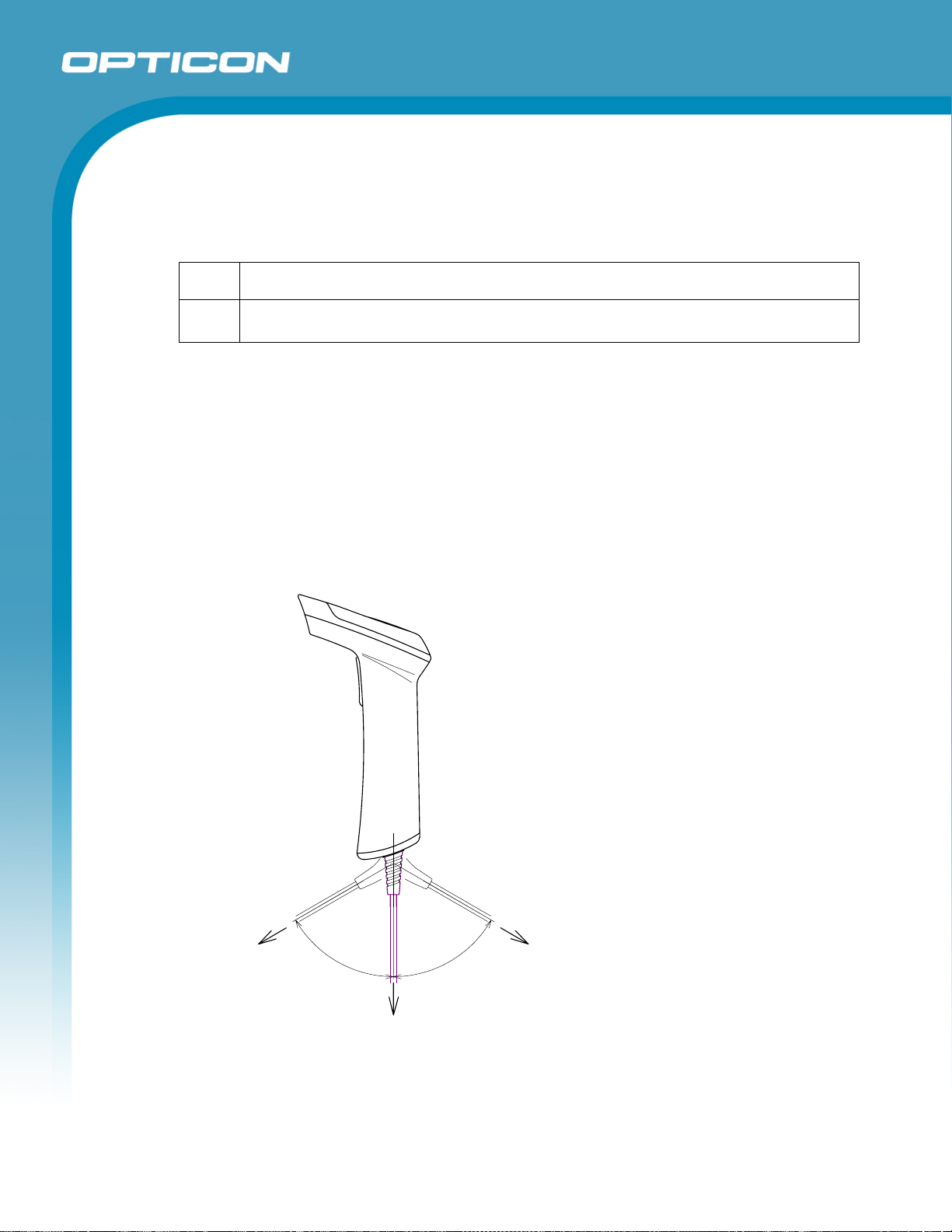
13.7. Cable Bending Test
There was no sign of malfunction with the scanner’s structure and its performance after
the following flexing test: Applied load 4.9N (or 500gf) to the cable and flex it 60 degrees
to the left and right as shown below. Repeated this routine one million times.
Opticon
OPL 7836
Note: Cable bending resistance is not warrantable.
6
5
0
0
f
g
9
.
N
4
)
(
0
°
°
0
6
4.9N(500gf)
4.9N(500gf)
Figure 27: Cable bending test
35
Page 36
Specifications Manual
14. Reliability
MTBF (Mean Time Between Failures) of this product except for the laser diode and the mirror
motor scan unit is 30,000 hours.
Life cycle of the laser diode is 10,000 hours and that of the mirror motor scan unit is also
10,000 hours.
The estimate of MTBF and product life cycle is based on standard operation of the product
within the recommended temperature range and without extreme electronic or mechanical
shock.
15. Trigger and Read Options
The OPL 7836 has read and trigger settings as follows:
15.1. Auto Trigger Options
15.1.1. Auto Trigger Sensor
The product has an optional auto trigger setting, which starts barcode reading
automatically by using sensor detection. The scanner starts barcode reading after
detecting reflection from the surface when the auto trigger is used.
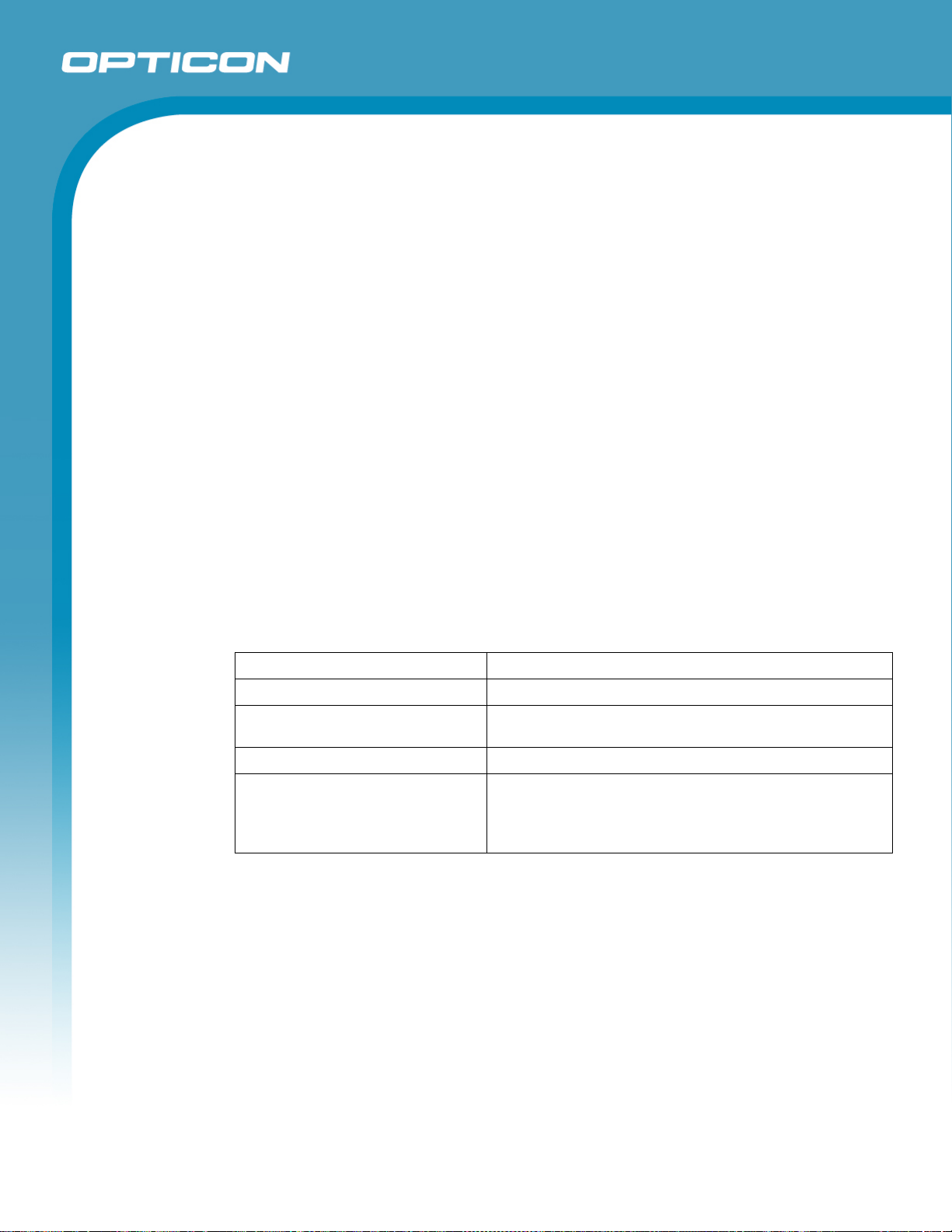
Auto trigger distance: 50 ±10 mm from the edge of the scanner.
Opticon
OPL 7836
Conditions
Moving speed: 100 ±10 mm/s
Angle: Vertical to the edge of the scanner
Environmental temperature and
humidity:
Environmental illuminance: 500 to 900 lx
Conditions for the auto trigger: 1. Barcode sheet: OPTOELECTRONICS Test Sheet (white)
Room temperature and humidity
Background: OPTOELECTRONICS Test Sheet (black)
2. Barcode sheet: OPTOELECTRONICS Test Sheet (black)
Background: OPTOELECTRONICS Test Sheet (white)
36
Page 37
15.2. Auto Trigger Settings
15.2.1. Enable/Disable Settings
Use the following settings to enable or disable the auto trigger. (Auto trigger is
disabled by default).
To enable auto trigger, scan “ZZ”, “+I” and “ZZ” in that order.
To disable auto trigger, scan “ZZ”, “+F” and “ZZ” in that order.
Functions Menu labels Menu codes
Opticon
OPL 7836
Specifications Manual
SET
Disable auto trigger
Enable auto trigger
END
Note: Please configure the following after enabling the auto trigger.
_ZZ_
_+F_
_+I_
_ZZ_
ZZ
+F
+I
ZZ
37
Page 38

16. Regulatory Compliance
16.1. Laser Safety
The scanner emits laser beams.
JIS C6802: 2005: Laser class 2
IEC 825-1/EN 60825-1: Laser class 2
FDA CDRH Laser class II. Complies with 21 CFR 1040.10 and 1040.11 except for
deviations pursuant to laser notice No. 50 dated June 24, 2007.
Class II laser devices are not considered to be hazardous when used for their intended
purpose. Avoid staring into the laser beam.
16.2. Product Safety
EN60950-1: 2001
IEC60950-1: 2001
Opticon
OPL 7836
Specifications Manual
16.3. EMC
EN55022
EN55024
VCCI Class B: This is a Class B product, to be used in a domestic environment based on
the Technical Requirement of the Voluntary Control Council for Interference from
Information Technology Equipment (VCCI). If this is used near a radio or television
receiver in a domestic environment, it may cause radio interference. Please install and
use the equipment according to the instruction manual.
FCC Part 15 Subpart B Class B: This device complies with part 15 of the FCC Rules.
Operation is subject to the following two conditions: (1) this device may not cause harmful
interference, and (2) this device must accept any interference received, including
interference that may cause undesired operation.
16.4. RoHS
RoHS: The restriction of the use of certain hazardous substances in electrical and
electronic equipment, 2002/95 EC.
38
Page 39

17. Safety
Handle this product carefully. Do not deliberately subject it to any of the following.
17.1. Shock
Do not throw or drop the scanner.
Do not place heavy objects on the cables.
17.2. Temperature Conditions
Do not use the scanner at temperatures outside the specified range.
Do not pour boiling water on the scanner.
Do not throw the scanner into the fire.
Do not forcibly bend the cables at low temperatures.
17.3. Foreign Materials
Do not immerse the scanner in liquids.
Opticon
OPL 7836
Specifications Manual
Do not subject the scanner to chemicals.
17.4. Other
Do not plug/unplug the connectors before disconnecting the power.
Do not disassemble this product.
Do not place the product near a radio or a TV receiver, as the scanner may cause
reception problems.
The scanner may be damaged by voltage drops.
The scanner may not perform properly in environments when placed near a flickering
light, such as a computer monitor, television, etc.
39
Page 40
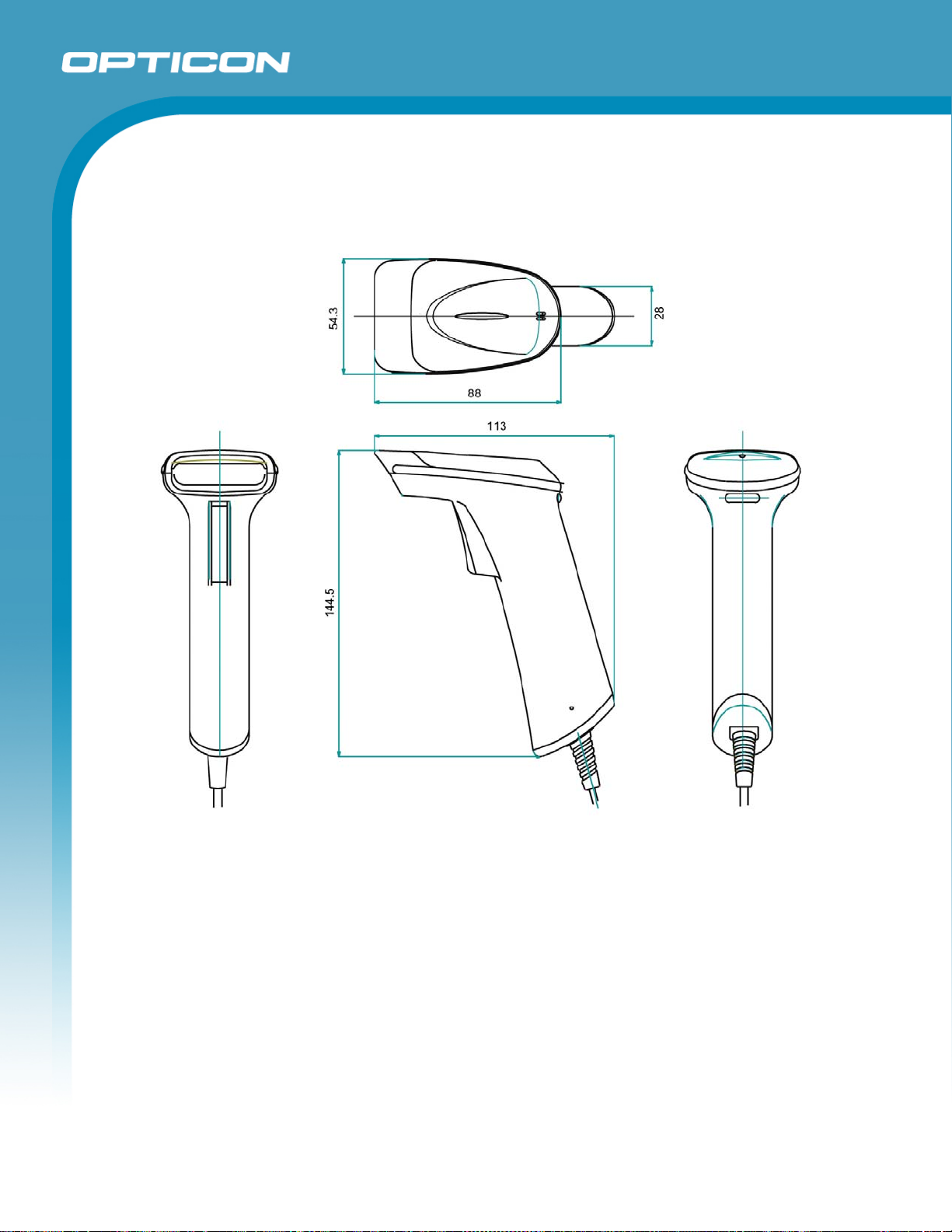
18. Mechanical Drawing
Dimensions: 144.5 x 113.0 x 54.3 (excluding cable connection)
Opticon
OPL 7836
Specifications Manual
Figure 28: Mechanical drawing
40
 Loading...