

Page 1
Page 2
2
Safety precautions
Install this equipment avoiding a direct ray of light, heats and moistures.
-Doing not, can result in lowering efficiency, electric shock or fire.
Do not pull electric wire or do not touch power plug with wet hands.
-Can result in electric shock or fire.
Do not bend the power cable forcedly or do not press it with heavy materials.
-Can result in electric shock or fire.
Do not use damaged power cord or loose outlet plug.
-Can result in electric shock or fire.
Do not use the outlet fully.
-Can result in electronic shock or fire.
Do not disassemble, repair or convert this product without permission.
-Can result in electric shock or fire. When repair is required, contact the service center.
Do not open the cover of the product at your convenience or do not insert inductive stick
into the ventilation hole.
-Especially, SMPS is open, so only professional technicians are allowed to work on.
Failure to follow these instructions could result in serious personal
injury or death.
Failure to follow these instructions could result in personal injury or
property damage.
Notifies user of references to use conveniently.
Do not place equipment on the inclined or uneven plane.
-Can cause lowering of efficiency or malfunction.
Do not vibrate or shock in operation.
-Can cause out of order with equipment and hard disk (HDD).
be caution that do not cover the ventilation hole of HDD or put liquid into the equipment.
-may cause out of order of equipment and hard disk drive (HDD)
Battery Caution : “Risk of Explosion if Battery is replaced by an Incorrect Type.
Dispose of Used Batteries According to the Instructions.”
Page 3
3
Contents
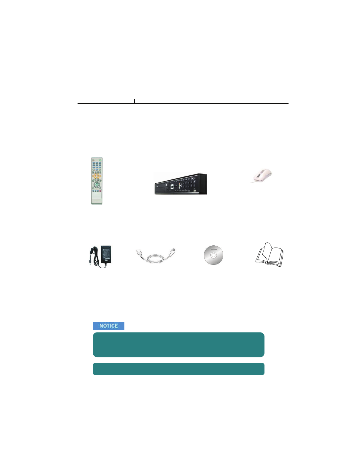
DVR Mainframe
Remote Controller (option)
Power Cord Set
USB Mouse (option)
Software CD
Operation Manual
Open the box at the clean and even place. And read operation manual thoroughly before you install.
Check the items supplied with your DVR system. Refer to the picture above
and contact your dealer if you find anything is missing or damaged.
The specification and appearance may be changed without prior notice.
DC Power Adapter
Page 4

4
Index
Chapter I. System overview
System Specification--------------------------------------------------------------------------------7
System Characteristics-----------------------------------------------------------------------------8
Chapter II. H/W description
System Appearance-------------------------------------------------------------------------------10
DVR Rear Panel------------------------------------------------------------------------------11,12
System Rear Connection detail----------------------------------------------------------------13
System Front Description----------------------------------------------------------------------16
Remote Control Description---------------------------------------------------------------------17
Installation Guide for HDD & ODD devices --------------------------------------------18,19
System on / shutdown----------------------------------------------------------------------------20
Chapter III. Monitoring Screen
Monitoring Screen---------------------------------------------------------------------------------22
Screen split, login----------------------------------------------------------------------------------23
Menu – Display-------------------------------------------------------------------------------------24
Menu – Spot, PTZ, Alarm------------------------------------------------------------------------25
Menu – Status--------------------------------------------------------------------------------------26
Menu – Record, Camera, Color, OSD-------------------------------------------------------27
Menu – Backup-------------------------------------------------------------------------------------28
Menu – Mute, Logout-----------------------------------------------------------------------------29
Chapter IV. Setup
System------------------------------------------------------------------------------------------------31
System – Information----------------------------------------------------------------------------32
System – Date/Time-----------------------------------------------------------------------------33
System – Disk-------------------------------------------------------------------------------------34
System – User------------------------------------------------------------------------------------35
System – Log, Logout, Shutdown-----------------------------------------------------------36
Network-----------------------------------------------------------------------------------------------37
Network – LAN------------------------------------------------------------------------------------38
Network – DDNS---------------------------------------------------------------------------------39
Network – Email----------------------------------------------------------------------------------40
Network – Callback------------------------------------------------------------------------------41
Device-------------------------------------------------------------------------------------------------42
Device – Camera---------------------------------------------------------------------------------43
Device – Alarm / Main Monitor----------------------------------------------------------------44
Device– Display / Spot Monitor---------------------------------------------------------------45
Device – Miscellaneous------------------------------------------------------------------------46
Record------------------------------------------------------------------------------------------------47
Record – Record policy / Record------------------------------------------------------------48
Event--------------------------------------------------------------------------------------------------49
Event – Motion------------------------------------------------------------------------------------50
Event – Sensor------------------------------------------------------------------------------------51
Event – Video loss-------------------------------------------------------------------------------52
Event – System-----------------------------------------------------------------------------------53
Page 5

Index
Chapter V. Search
Search screen--------------------------------------------------------------------------------------55
Menu – Display / Calendar search------------------------------------------------------------56
Menu – Event search / Date / Time search------- ----------------------------------------57
Menu – First, Last, Bookmark------------------------------------------------------------------58
Menu – Local device / Backup device-------------------------------------------------------59
Chapter VI. Client program
REMOTE---------------------------------------------------------------------------------------------61
Connection Info / Button-------------------------------------------------------------------------62
Program Info & Setup-----------------------------------------------------------------------------63
Icon Adjustment------------------------------------------------------------------------------------64
Remote search execute & setup--------------------------------------------------------------65
Menu – Remote setup (Camera)--------------------------------------------------------------66
Menu – Remote setup (Alarm)-----------------------------------------------------------------67
Menu – Remote setup (Record)---------------------------------------------------------------68
Menu – Remote setup (Record table)--------------------------------------------------------69
Menu – Remote setup (Record policy)-------------------------------------------------------70
Menu – Remote setup (Motion)----------------------------------------------------------------71
Menu – Remote setup (Motion link)----------------------------------------------------------72
Menu – Remote setup (Sensor)---------------------------------------------------------------73
Menu – Remote setup (Sensor link)----------------------------------------------------------74
Menu – Remote setup (Video loss)-----------------------------------------------------------75
Menu – Remote setup (Video loss link)------------------------------------------------------76
Menu – Remote setup (System)---------------------------------------------------------------77
Menu – Remote setup (Disk error/S.M.A.R.T)---------------------------------------------78
Menu – Remote setup (Disk error/S.M.A.R.T link)----------------------------------------79
Play & Pause / Audio transmission / Mouse click to right------------------------------80
Channel button/Layout change button-------------------------------------------------------81
PTZ operation---------------------------------------------------------------------------------------82
Remote search (Image playback screen / Section)--------------------------------------83
Remote search (Hotkey & Event search)---------------------------------------------------84
Remote search (Connection info / button / playback button)--------------------------85
Remote search (Split screen change / Audio / Image control button)---------------86
Remote search (Saving related button)-----------------------------------------------------87
Remote search (Preview)------------------------------------------------------------------------88
Remote search (Mouse click to right)--------------------------------------------------------89
Remote search (Time table)--------------------------------------------------------------------90
Backup playback-----------------------------------------------------------------------------------91
PLAYER----------------------------------------------------------------------------------------------92
5
Chapter VII. APPENDIX
Front Key---------------------------------------------------------------------------------------------96
Hot Key-----------------------------------------------------------------------------------------------97
Product Warranty----------------------------------------------------------------------------------98
Page 6

Chapter-I. System Overview
6
Page 7

Chapter I
/; /; /;
9LGHR,1/RRS2XW
9LGHR'LVSOD\
0RQLWRU2XW FK&RPSRVLWLRQ
9*$2XW FK
6SRW2XW FK
$XGLR,Q2XW LQRXW
$XGLR&RPSUHVVLRQ *
'LVSOD\5HVROXWLRQ [
5HFRUGLQJ5HVROXWLRQ [[[
9LGHR&RPSUHVVLRQ 0SHJ/HYHO
'LVSOD\
)UDPH
176& ISV ISV ISV
3$/ ISV ISV ISV
5HFRUG
)UDPH
176& 'ISV &,)ISV &,)ISV
3$/ 'ISV &,)ISV &,)ISV
3OD\EDFN
)UDPH
176& 'ISV &,)ISV &,)ISV
3$/ 'ISV &,)ISV &,)ISV
26 (PEHGGHG/LQX[
1HWZRUN %DVH7($
86% 86%)URQW($5HDU($
(,'( FK0D[($+''
6$7$ &K0D[($+''
&RQVROH 56&
37= 56
$ODUP)XQFWLRQ,Q2XW
)URQW.H\ .H\
5HPRWHFRQWUROOHU ,'5HPRWHFRQWUROOHU
:DWFKGRJ3RZHUPRQLWRU <HV
/&' 1RQH
)URQW/(' 3RZHU1HWZRUN+''
'LPHQVLRQ :['[+PP
2SHUDWLRQWHPS a
2SHUDWLRQKXPLGLW\ a
:HLJKW NJ:LWKRXW&'5:+''
3RZHU $GDSWHU'&9+]$$GDSWHU'&9+]$
System Specification
7
Page 8
Chapter I
System Characteristics
¾ Up to D1(720*480) recording
¾ High level specification with elegance design and jog/shuttle, easy UI with LCD
¾ Control recording resolution, quality, frame rate by each camera
¾ USB mouse supported
¾ LIVE screen editing, Digital zoom, SPOT monitor supported
¾ Event / Panic / Schedule record, optimized record mode supported
¾ Diversified search by Time, Calendar, Event supported
¾ Diversified backup by USB2.0 and DVD-RW supported
¾ Convenient backup by AVI , Mini viewer etc
¾ 10/100 Base-T network
¾ DDNS, NTP, E-MAIL, CALLBACK functions
¾ DISK ID, S.M.A.R.T functions, real-time disk health check
¾ Multi-language supported
¾ Intensive security function by chosen AUTHORITY
8
¾ Diversified network program by LIVE, SEARCH, CMS, AGENT
Page 9

9
Chapter-II. H/W Description
Page 10
Chapter II
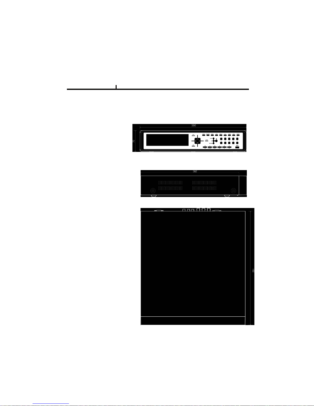
System appearance
1) Front View
2) Side View
10
3) Top View
Page 11
11
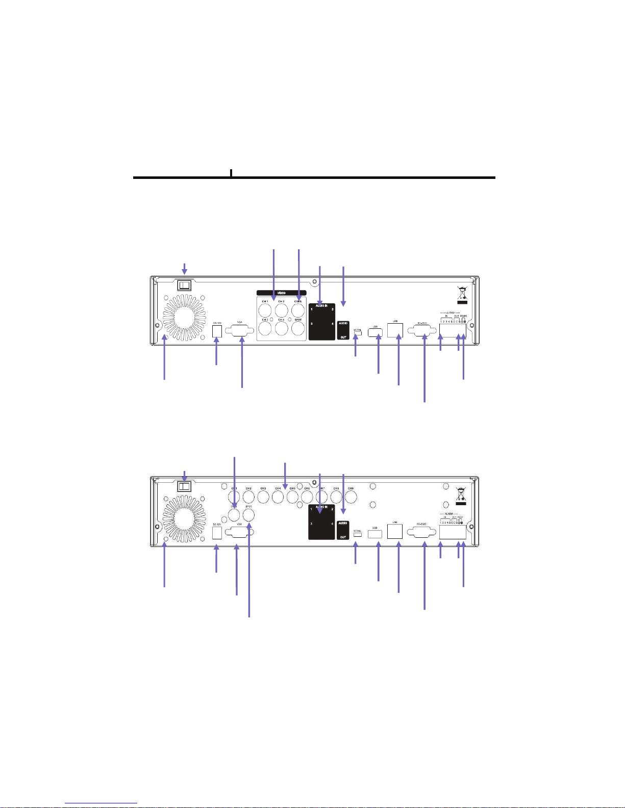
DVR rear panel
Chapter II
Video Input
(4CH)
Video
Output
Power Input
DC12V
Alarm
In/Out
Network Port
USB Port
RS232
Port
VGA
Port
FAN
NT/PAL
switch
Audio In/Out
RS485
Power
switch
1) 4CH Rear Panel
2) 9CH Rear Panel
!"#
Power
switch
Video
Output
Video Input
(9CH)
Audio In/Out
Power Input
DC12V
NT/PAL
switch
VGA
Port
Spot
Output
USB Port
Network Port
RS232
Port
Alarm
In/Out
RS485
Page 12
12
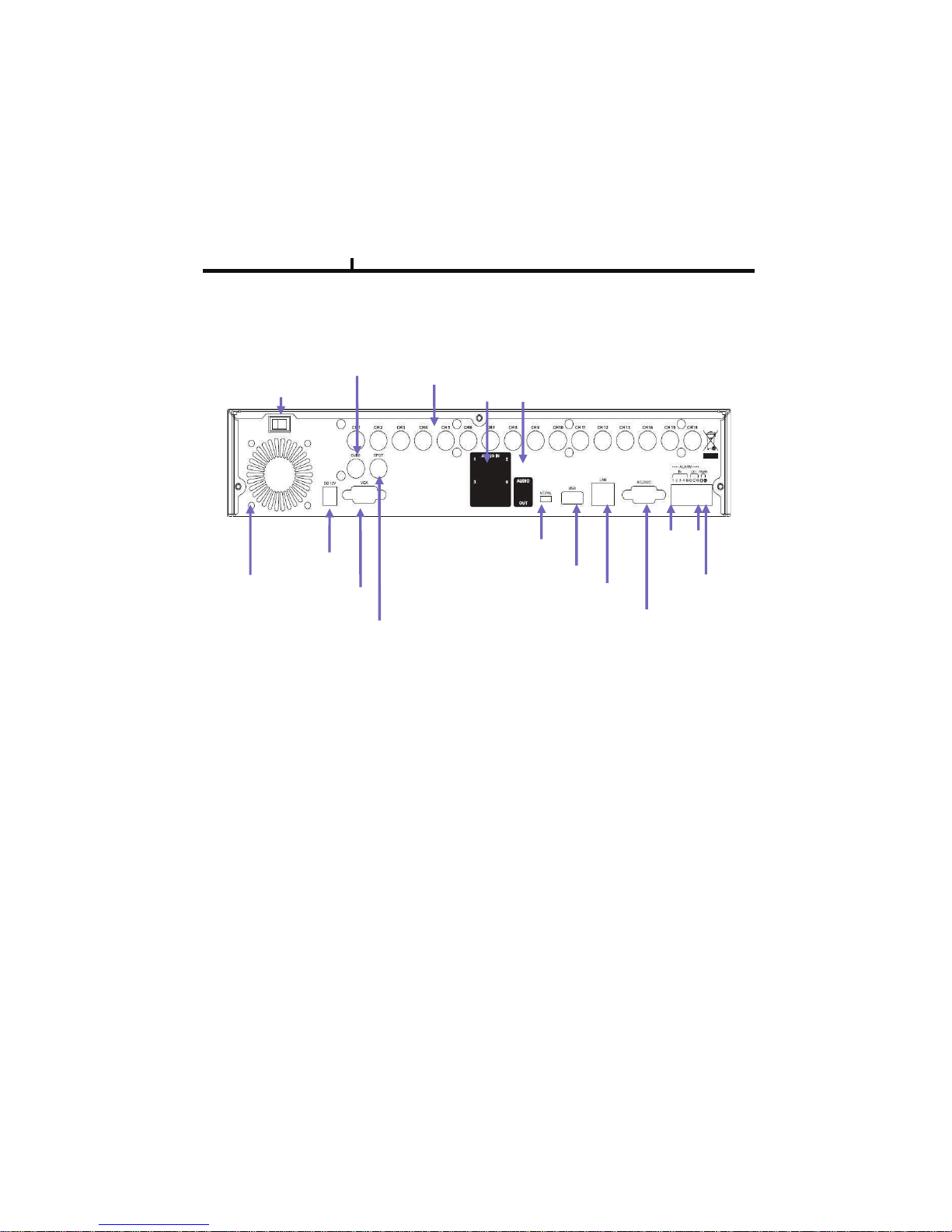
DVR rear panel
Chapter II
3) 16CH Rear Panel
!"#
Power
switch
Video
Output
Video Input
(9CH)
Audio In/Out
Power Input
DC12V
NT/PAL
switch
VGA
Port
Spot
Output
USB Port
Network Port
RS232
Port
Alarm
In/Out
RS485
Page 13
Chapter II
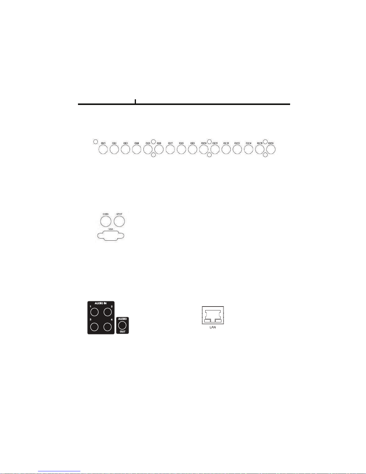
4) Network Connection
It connects audio source (mic) to audio
input (4CH) of RCA and connects
speaker to audio output.
It supports 10/100 BaseT, connects
Cat5 cable with RJ-45
System rear connection detail
1)Video Source Connection
It connects video sources (camera image) to BNC connector via cable.
2) Monitor Connection
CVBS/ SPOT OUT : It connects normal CCTV CRT monitor.
VGA : It connects PC monitor or LCD monitor (not supporting DVI)
13
3) Audio Connection
Page 14
14
Chapter II
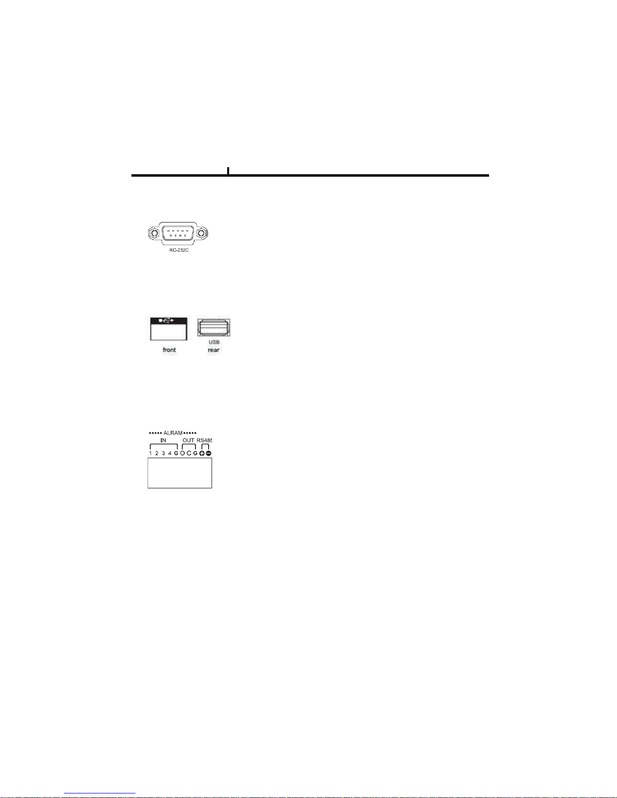
* Alarm Input 1~4CH
When an event happens DVR operates by using external device.
Sensor, Switch signal (Signal GND) are connected terminal block.
Ref : Spec. Max 6V/50mA
* Alarm Output 1CH
It can be on/off external device as buzzer, headlamp etc.
Alarm input mode consists of NORMAL OPEN and NORMAL CLOSE.
Ref : Spec. Max24V/2A
* RS485
Through Half-duplex serial communication, remote controlling is available using control system
as external device, control keyboard.
In addition, it is available to control PTZ (Pan/Tilt/Zoom) camera.
it is connected RS485 +,- of DVR.
5) RS232 port Connection.
RS232 port is connected to PC and other devices for specific function and After Sales purpose.
It consists of 1 USB (Front), 1 USB (Rear), its supported devices are such as USB mouse, USB
external HDD and USB memory stick
6) USB port Connection
7) ALARM IN/OUT(SENSOR) Connection
Page 15

15
Chapter II
Adaptor is DC12V /5A input and Main Power can turn on/off DVR on Switch.
8) NTSC/PAL Shift Switch
NTSC/PAL Shift Switch
9)Power Connection
The factory reset switch located at the left side of NTSC/PAL switch is used to return to factory
default setup values.
When you need to shift NTSC/PAL mode, turn off the DVR before shift switch, then restart the DVR.
Page 16
Chapter II
@5A21/()**/
<24A51B('!*
CD&EFG
@H:I?:3B
!D+
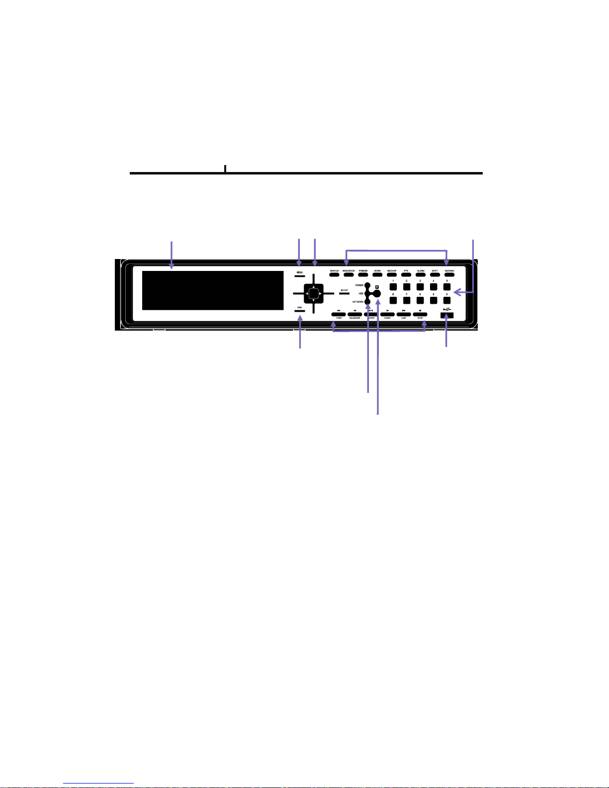
System Front Description
16
!"#$%&'!()**( %+,(
+*- ./*$*- .
¾ Menu Button : it shows menu in live, search display (same function as right click of mouse)
¾ Direction Button : It is used for movement, changing set-up, PTZ move, etc in menu.
(Basic function- left, right : Movement / up, down : Changing set-up / Enter : confirmation
¾ Number Button : It is used for Changing to 1CH screen, direct input in set-up.
"26=
*01234056
#921:406;
7 (826851
<=>?21
¾ Operating Button : It is used for operating function as Setup, Backup etc in DVR.
¾ ESC Button : It is used for exit from menu/mode, withdrawing from execution.
¾ LED : It shows status of Power, HDD, Network.
¾ IR sensor : it receives a signal of remote controller (remote controller is optional)
¾ Playback Button : It is used for when search, playback, Pause, FF, REW.
(It comes to live screen out of playback screen when stop button is pressed)
Page 17
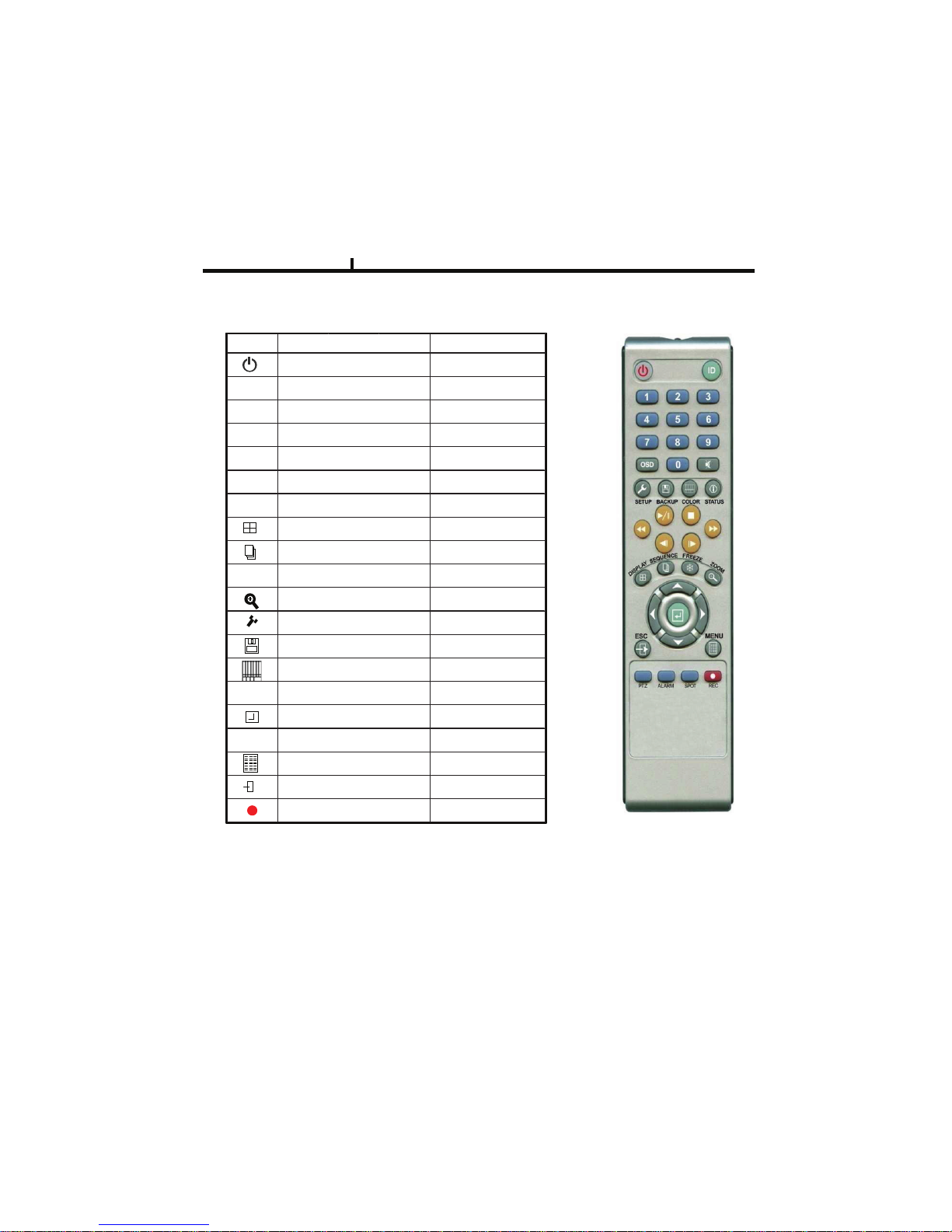
$$$$ How to change remote controller ID
A) Enter 'ID' button for 3seconds
B) Power LED is lightened.
C) Enter 2 letters of digit. (00 ~ 99) – In case 00, means no ID function
- ID set is available from 01 to 99.
D) Save setting value, then LED is off.
E) It enables to communicate the same ID DVR
F) LED is ON every time data is transferred.
Remote controller Description (Optional)
Chapter II
ICON HOT KEY
LATEST SEARCH
TO LIVE
FIRST SEARCH
LAST SEARCH
CALENDAR SEARCH
EVENT SEARCH
RECORD
SETUP
BACKUP
COLOR
STATUS
ENTER
DIRECTION
MENU
ESCAPE
DISPLAY
SEQUENCE
FREEZE
ZOOM
REWIND
FAST FORWORD
STEP REVERSE
STEP FORWORD
FUNCTION
POWER O N/OFF
PLAYBACK & PAUSE
STOP
!
! !
!
""""
##
####
##
!!
!!!!
!!
#
# #
#
!
! !
!
7777
$$$$ #### !!!!
%%%%
####
!
1
17
Page 18
Chapter II
ODD
MAIN
BOARD
HDD
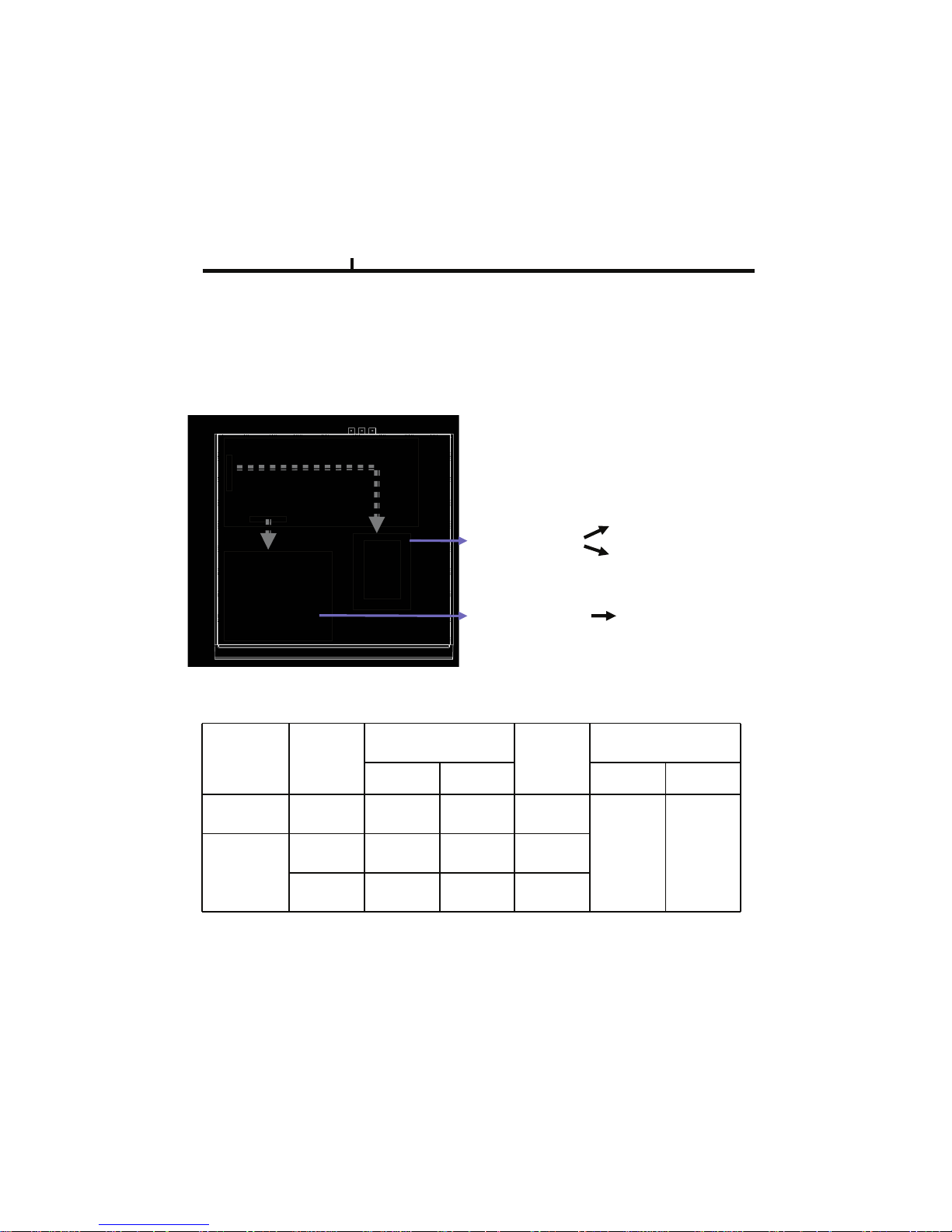
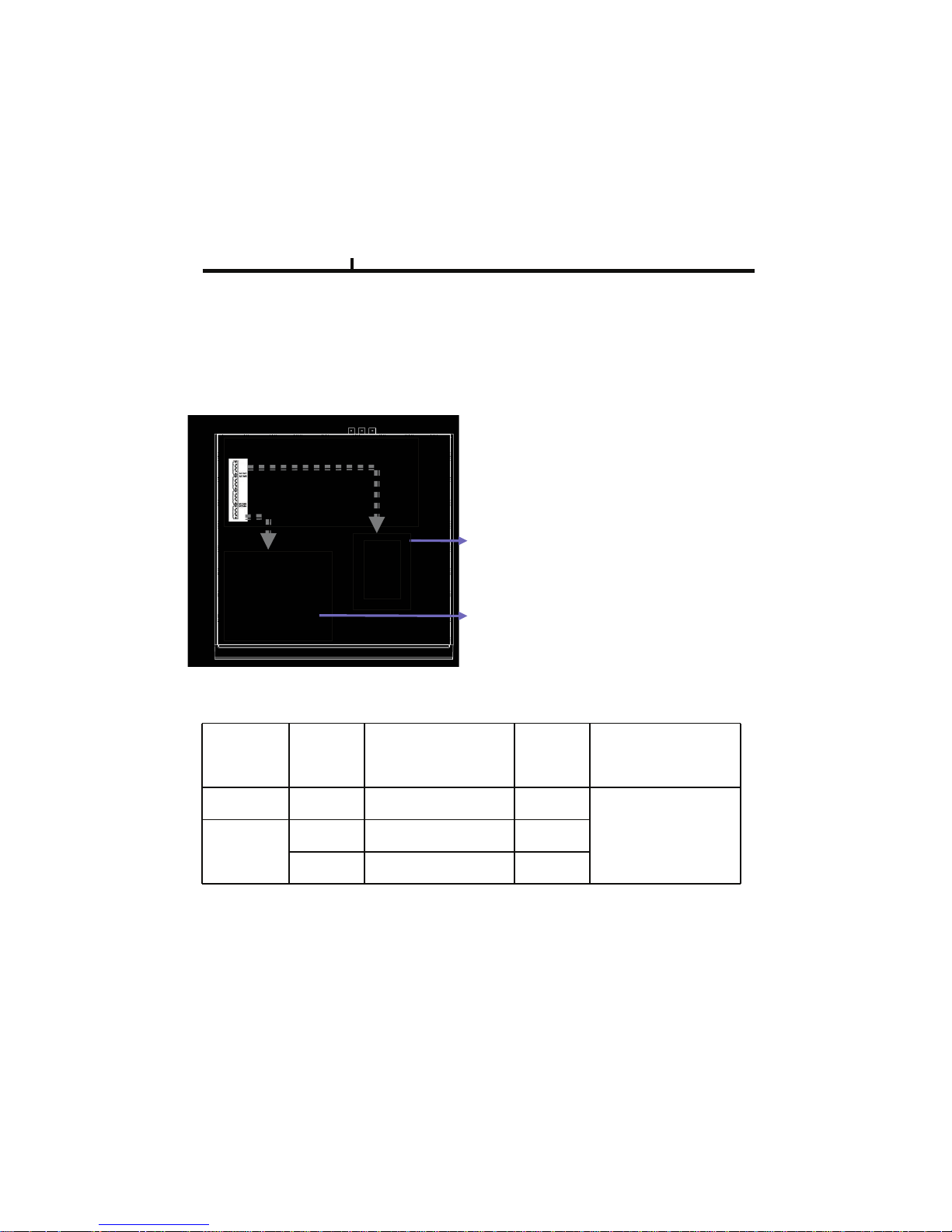
1. ODD(CD-RW/DVD-RW) devices should be installed as “Secondary Slave”.
2. HDD for system needs to be installed as “Primary”.
Guide Chart for installing several HDDs
Installation Guide for HDD & ODD devices (E-IDE Type)
Description
18
Installed HDD
HDD x 1 HDD#1
HDD#1
HDD x 2
HDD#2
PRIMARY
PRIMARY
PRIMARY
JF 1 : PRIMARY
MASTER : HDD#1
SLAVE : HDD#2
JF 4 : SECONDARY
HDD
System
SLAVE : ODD(CD/DVD)
ODD(CD-RW/DVD-RW)
Device
IDE Connector IDE Connector
MASTER
MASTER
SLAVE
JF1 SYSTEM
JF 1 SYSTEM
JF 1
SECONDARY
SLAVE
JF 4
Page 19
Chapter II
1**
7!8"
91!:*
HDD
Installation Guide for HDD & ODD devices (SATA Type)
Description
1. ODD(CD-RW/DVD-RW) devices should be installed as “SATA 4”.
2. HDD for system needs to be installed as “SATA 1”.
%!&!'#(#)**+'
19
%!&!,#(#)**+,
%!&!-#./#%!&!0#(#1**23*4*5*6
Guide Chart for installing several HDDs
Installed HDD HDD Position System
HDD x 1 HDD#1 SATA 1 SYSTEM
HDD#1 SATA 1 SYSTEM
HDD x 2
HDD#2 SATA 2
ODD(CD-RW/DVD-RW)
Device
SATA 4
Page 20
Chapter II
System On
• Put the power to the DVR.
• Turn on the power switch at the rear power button .
• It takes about 2minutes to boot (It may take more when network cable isn’t connected)
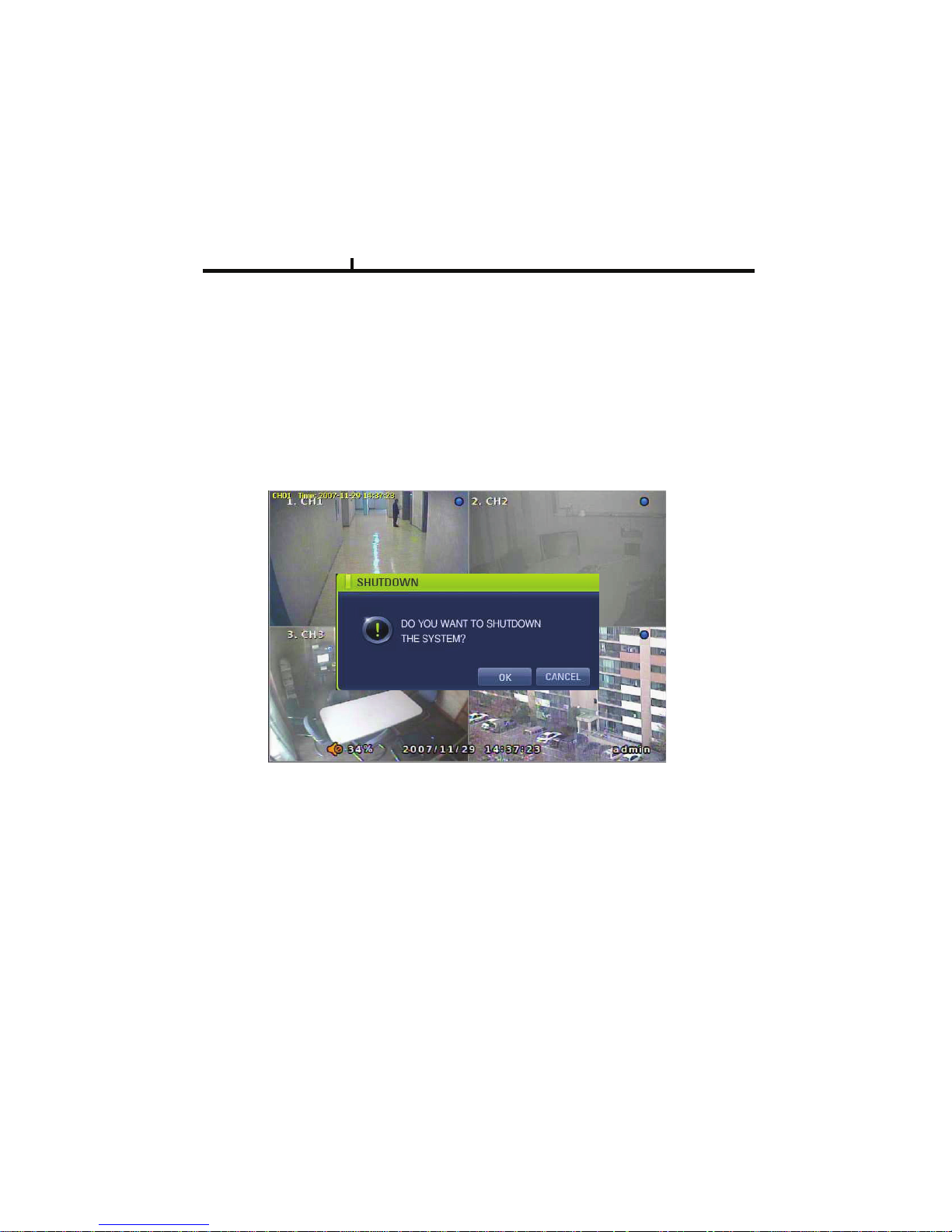
System Shutdown
•Select [SETUP > SYSTEM > SYSTEM SHUTDOWN] to shutdown system at login status
• Press “OK” button to confirm “Power off the system”, then turn off power switch in the rear.
20
Page 21

21
Chapter-III. Monitoring Screen
Page 22
1
2
Monitoring Screen
Chapter III
1
2
22
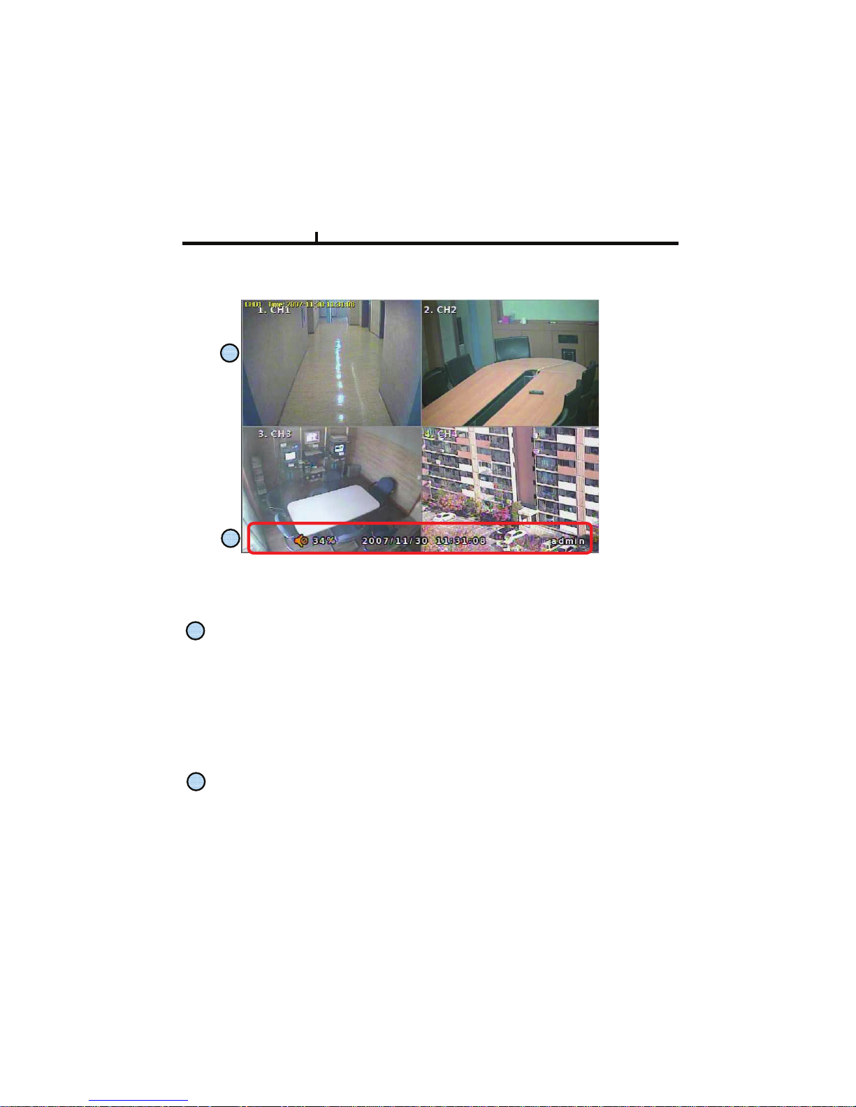
Monitoring screen : it monitors each channel.
<Screen Indication>
Left Up : Camera Name
P – Pan/tilt
A – Audio
Right Up : Record mode (Blue-Normal, Red-Event)
Motion status
Central : Video Loss, Hidden Camera
Status Bar : DVR status Indication
(Backup, HDD usage, Current Time, SEQUENCE, FREEZE, Login info. etc)
Page 23
Chapter III
1
2
3
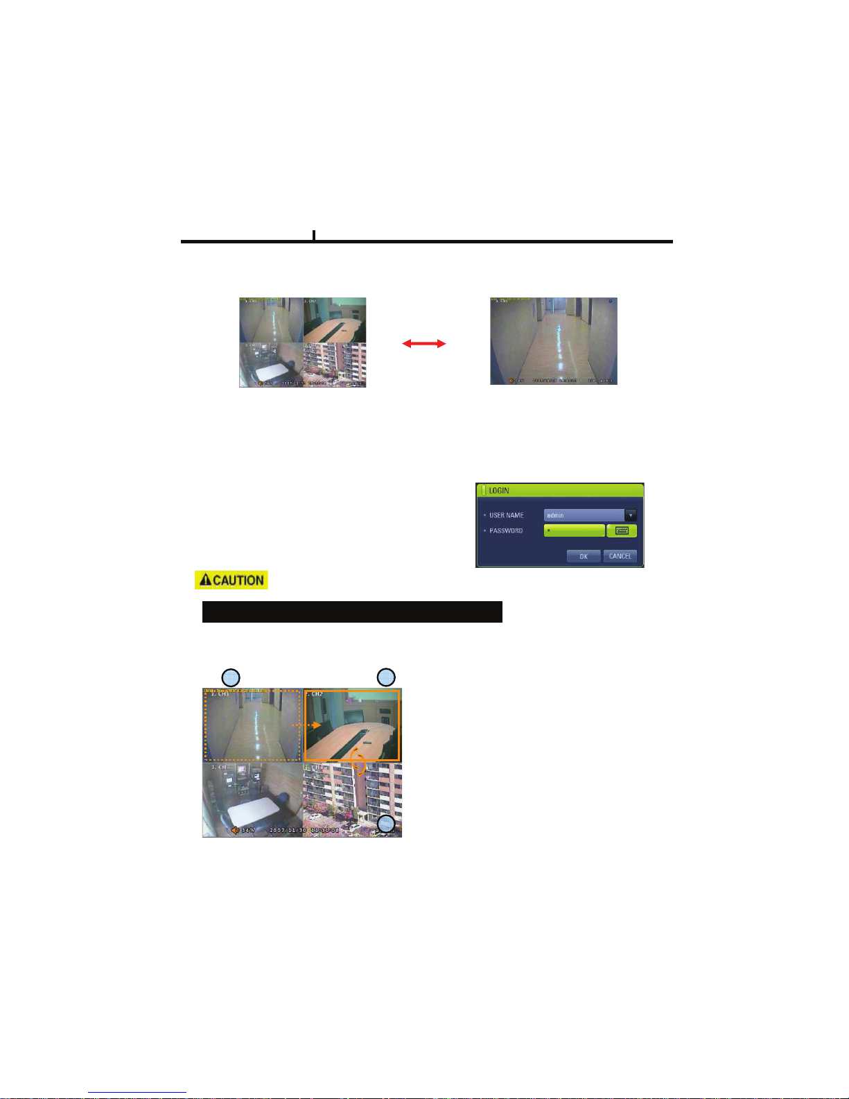
Screen Split
Press DISPLAY button or mouse menu: changed on 1 Æ4 by turn
Direct Channel
1) Press channel No. on the remote control or front panel.
2) Click the screen to watch specific channel using mouse.
LOG IN
Login to menu for setup
Default: ID –
PASSWORD - 1
It is recommended to change ID and PW for your safety.
admin
23
CAMERA ALLOCATION function (changing camera display position)
Ex) Switching camera No 2 and 4.
1)Making show up Menu by clicking mouse right
button or pressing menu key of remote controller
in monitoring status, then ETC Î select group
EDIT.
2)When box of orange color shows up on No.1
CH, by using key of up/down/left/right, move to
desired channel to switch
3)Enter channel no. you wish to switch.
4) To exit, press ESC or Enter
.
Page 24
24
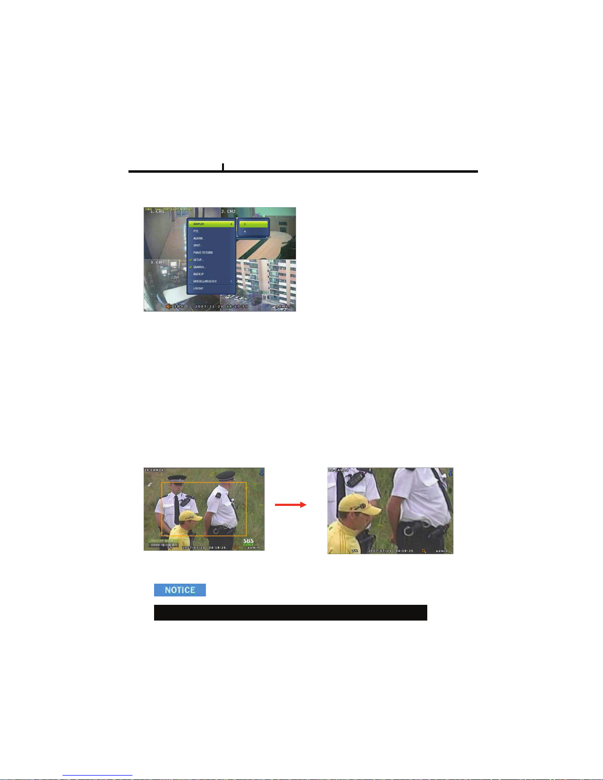
Menu Bar * Click MENU button or right button of mouse
DISPLAY
1, 4
: Split screen change (the same as DISPLAY button)
ZOOM
1 Full Live screen available only.
Select Zoom : Press zoom button and locate the box to magnify using direction keys
Move Zoom : It can be moved using direction key after press Enter.
Zoom screen may provide low quality or be shaken as formatted digitally.
<ZOOM selected screen>
<ZOOM screen>
Chapter III
SEQUENCE
Sequence camera group regularly
FREEZE
Pause the screen
MISCELLANUEOUS
Page 25
25
Chapter III
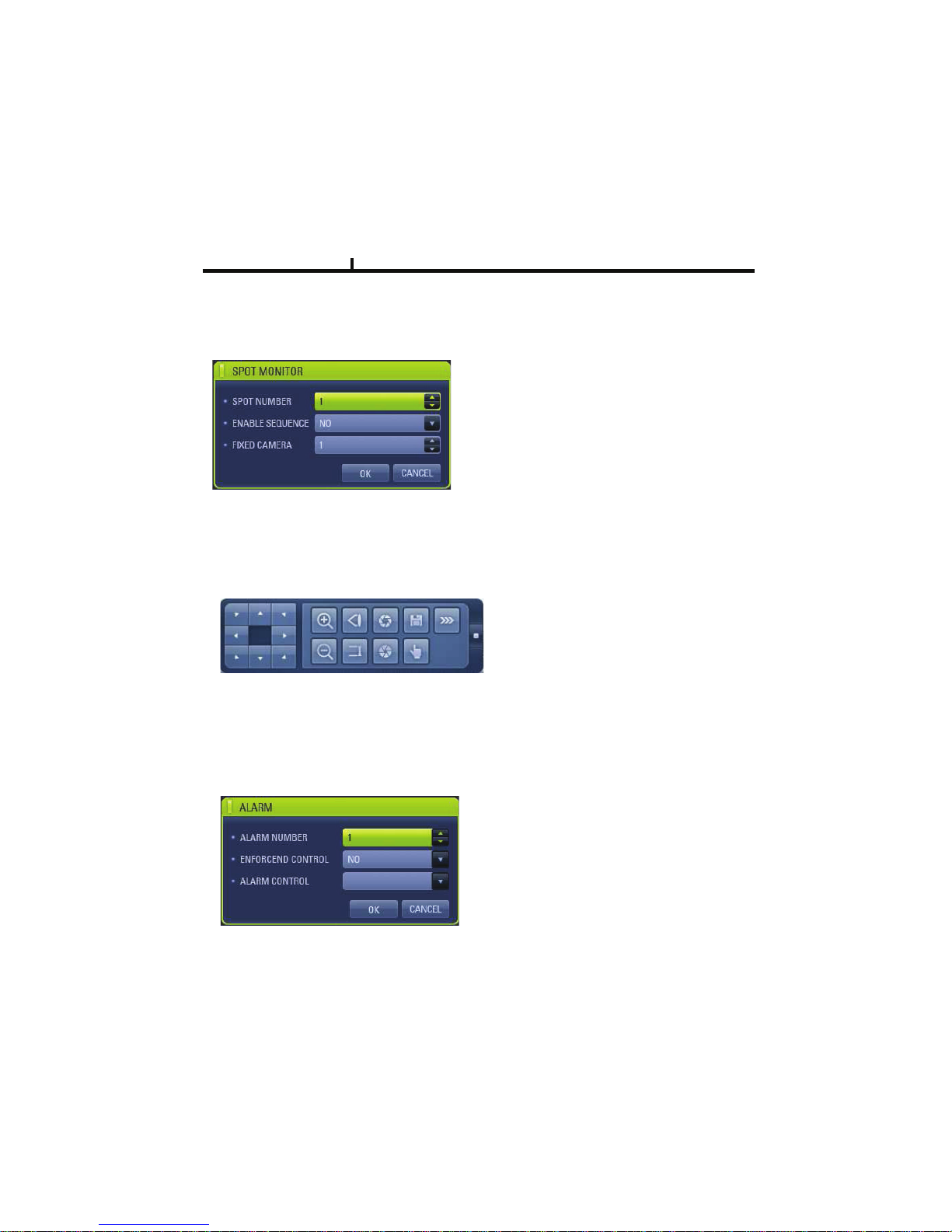
PTZ
Pan Tilt/Zoom/Focus/Iris Preset setting and moving functions are supported.
Each function can be different from each PTZ protocol.
ALARM
Control Alarm output function.
SPOT
1 spot monitors are supported and sequence / fix mode can be selected.
Select the Spot monitor in SETUP>DEVICE>SPOT MONITOR.
Page 26
26
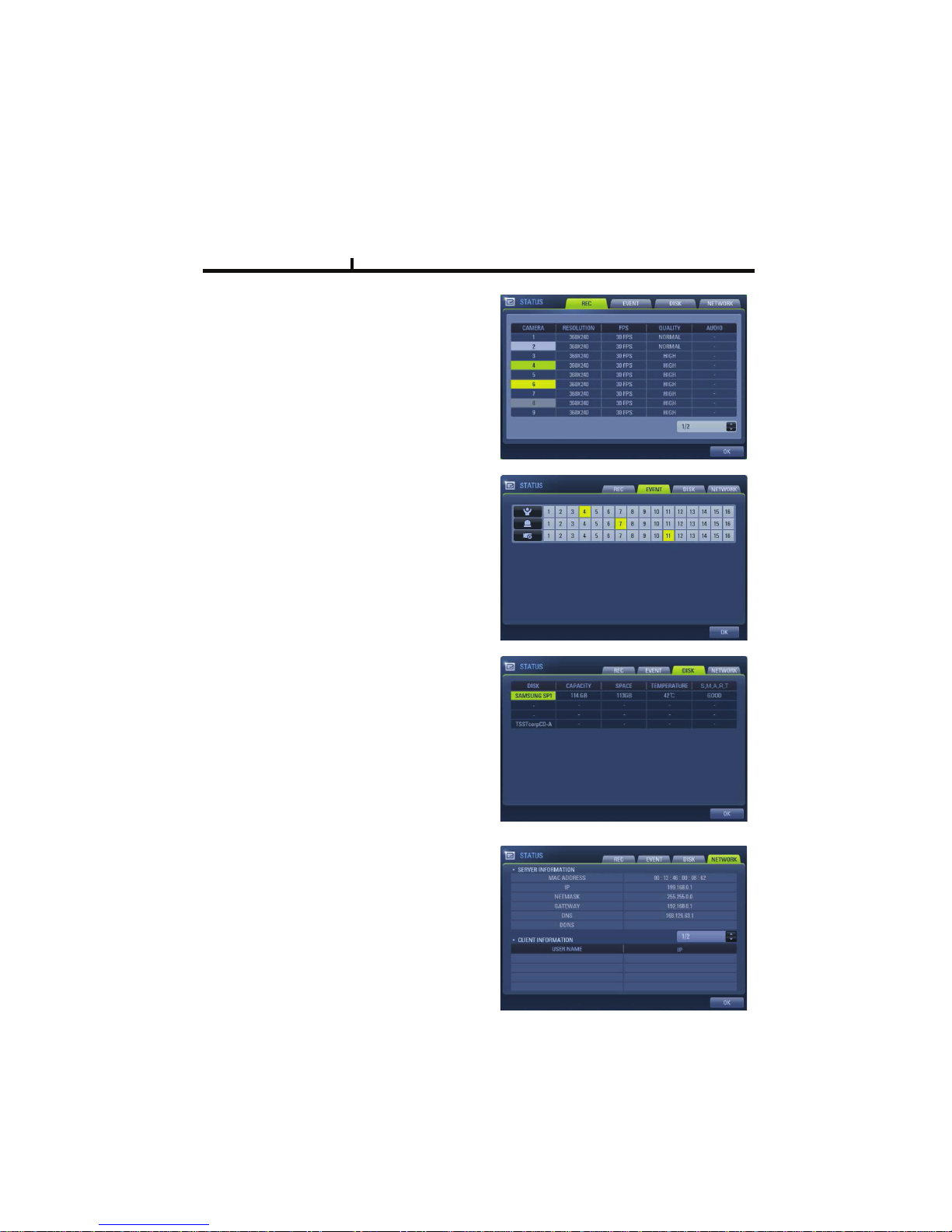
STATUS
RECORD
Displays current recording status
EVENT
Displays current event information (motion/alarm).
DISK
Displays current Disk information
NETWORK
Displays current network information.
Also displays current connected client information.
Chapter III
Page 27
27
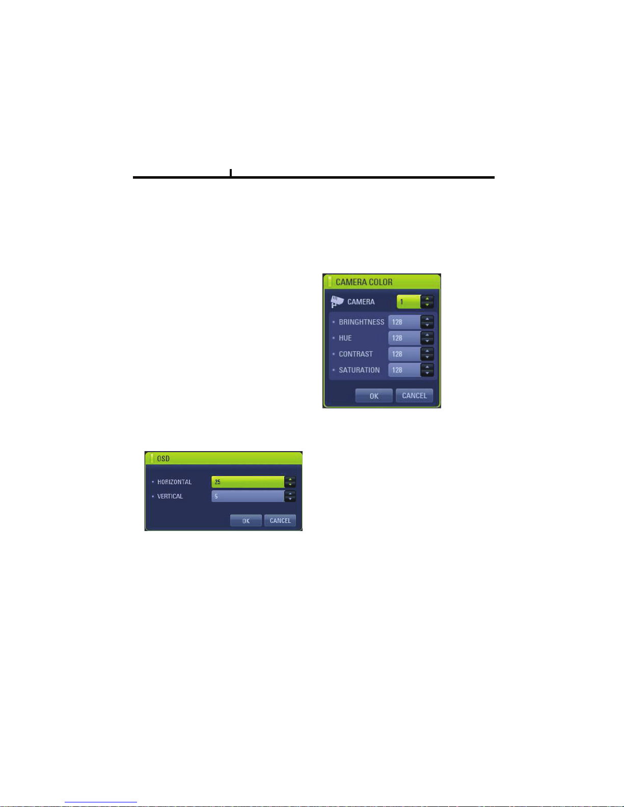
PANIC RECORD
Set recording mode in an emergency situation.
Press SETUP>RECORD> EVENT RECORD>FPS/QUALITY
SETUP
Select to enter into SETUP menu
CAMERA COLOR
Changes camera screen color
OSD
Changes OSD (On Screen Display)’s position.
SEARCH
Select to enter into SEARCH menu
Chapter III
Page 28
28
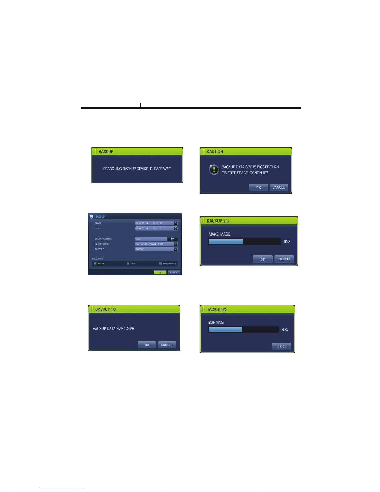
BACKUP
Select to backup recorded data.
1) Backup Device Search
2) Select data to backup
3) Calculate data size
4) Warning when data size is over
5) Make Image after pressing OK.
6) Burning to CD
Chapter III
Page 29

29
MUTE
Sound off
LOGOUT
Press SETUP>SYSTEM>USER
Chapter III
Page 30

30
Chapter-IV. SETUP
Page 31
Chapter IV
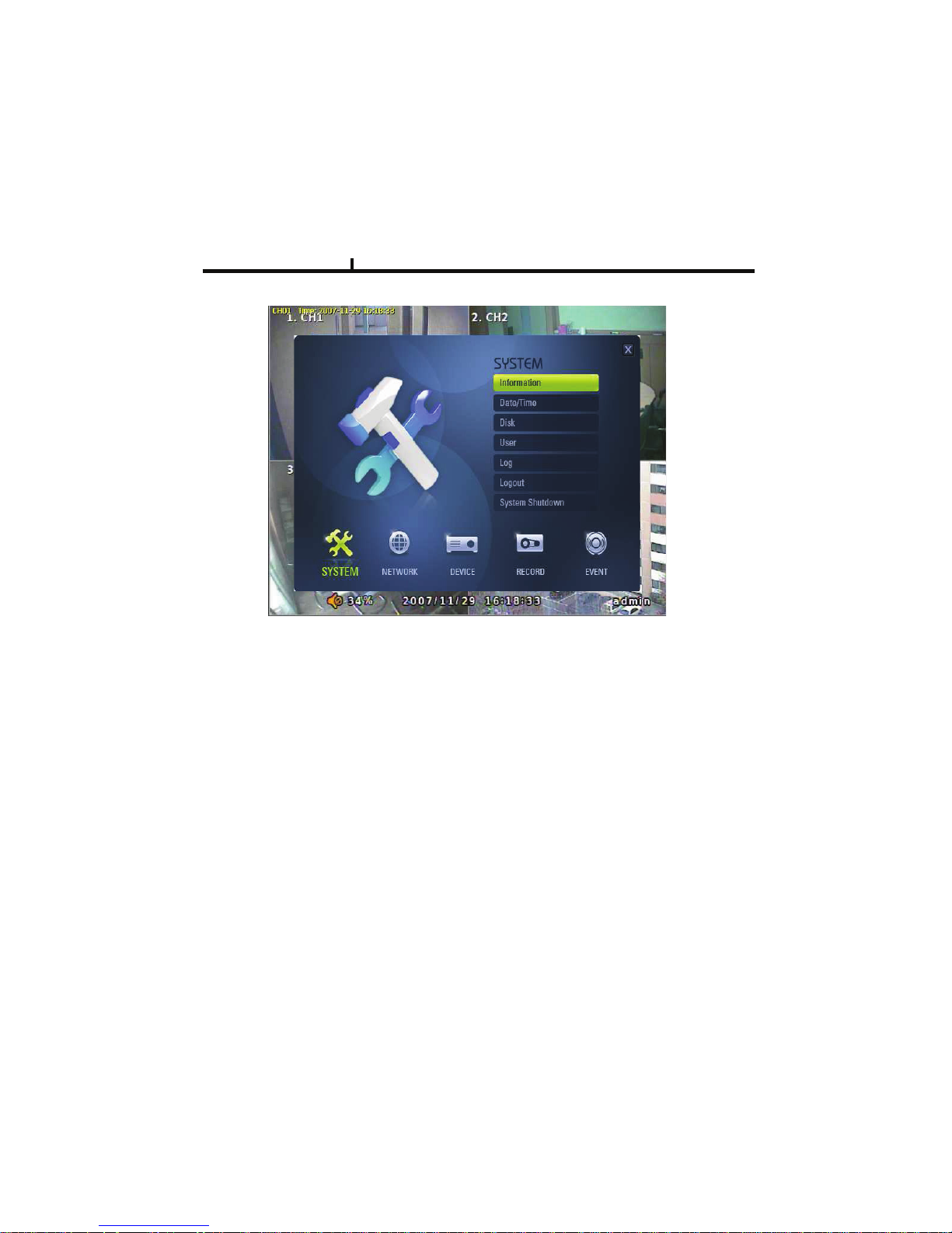
SETUP SCREEN
SYSTEM
Set up various system related items.
INFORMATION
DATE/TIME
DISK
USER
LOG
LOGOUT
SYSTEM SHUTDOWN
31
Page 32
32
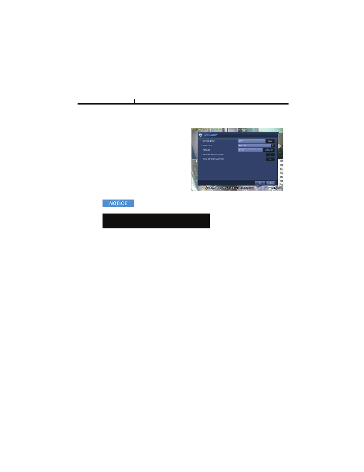
INFORMATION
DEVICE NAME: User can change the DVR
name on his own.
LANGUAGE : Select language.
VERSION : Shows S/W version info.
(With UPGRADE button, you can upgrade
the newest S/W version)
INFORMATION
Contact manufacturer or distributors for more
Upgraded version .
CONFIGURATION IMPORT : You can read setup values saved in USB or
Initialize the setup values
CONFIGURATION EXPORT : You can record setup values in USB equipment.
Chapter IV
Page 33
33
DATE/TIME
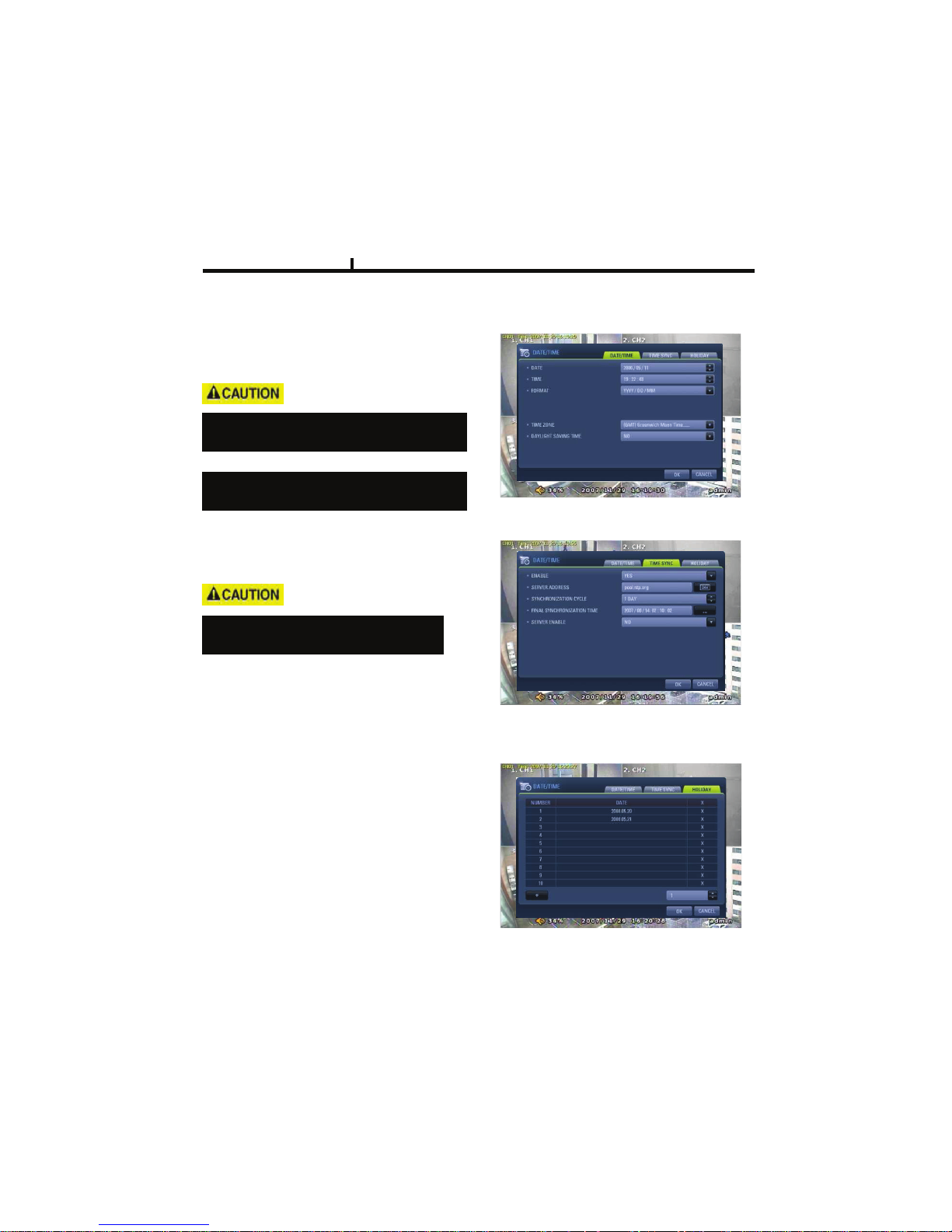
DATE/TIME
Set date, time & Time zone of System.
When you use it for the first time
Set these items in advance .
TIME SYN
Synchronize time with internet time server.
Set the GMT on the DATE/TIME list and
Adjust TIME SYNC.
HOLIDAY
In the schedule record setup , it automatically
converts normal date to holiday schedule.
It works when record is setup as schedule mode.
Chapter IV
Check “NO” of enable in the TIME SYNC
menu, user can change DATE/TIME
Page 34
34
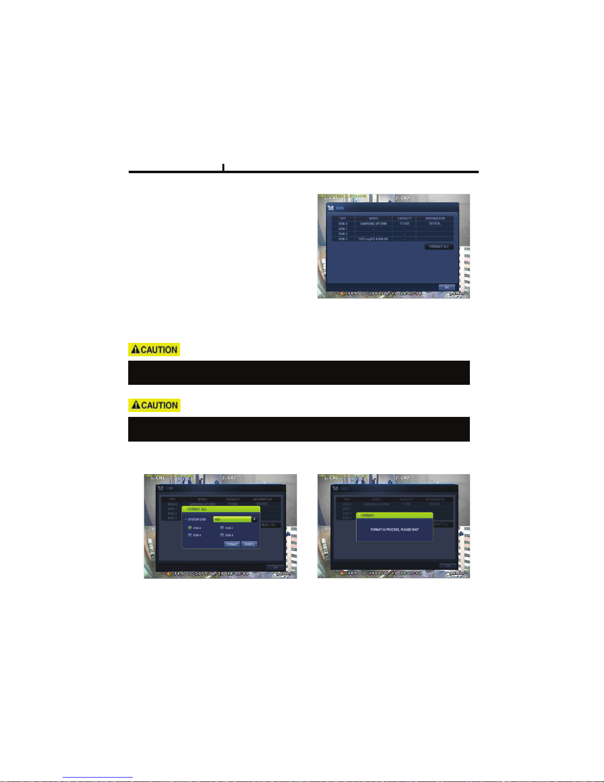
DISK
DISK TABLE
Shows current disk information connected to
system.
IMPORTED : DISK installed
RECORD : RECORD possible
SYSTEM : DISK allotted for SYSTEM
TOTAL DISK FORMAT
Format all connected HDD disks.
(When you select info column of connected DISK separately,
You can format DISK one by one.
One of DISKS should be a system disk for recording system logs & other TEMP file issuing
purposes.
<SYSTEM DISK selected Screen> <On FORMAT Screen>
Chapter IV
Backup devices such as CD-RW/DVD-RW need to be installed as Secondary Slave.
(JF 4 Connector. – Slave jumper setting)
Page 35
35
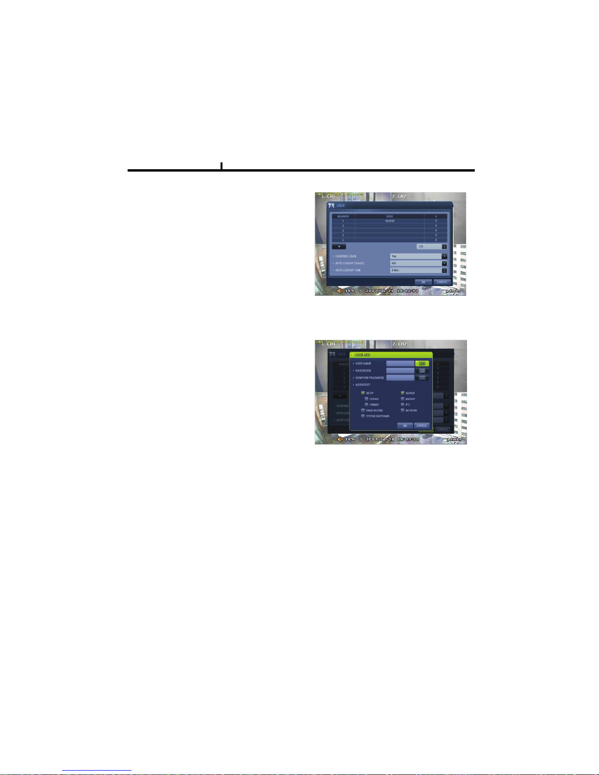
USER
USER
Shows currently registered user lists.
User accounts can be added or deleted.
+
add account with this button.
X Delete account with this button.
USER ADD
Possible to add user account
according to authority.
CONFIRM LOGIN
When YES selected, LOGIN needs to be confirmed every time to enter into setup /
system menu.
AUTO LOGOUT ENABLE
LOGOUT automatically after a certain period of time.
AUTO LOGOUT TIME
Set idle time to LOGOUT
Chapter IV
Page 36
36
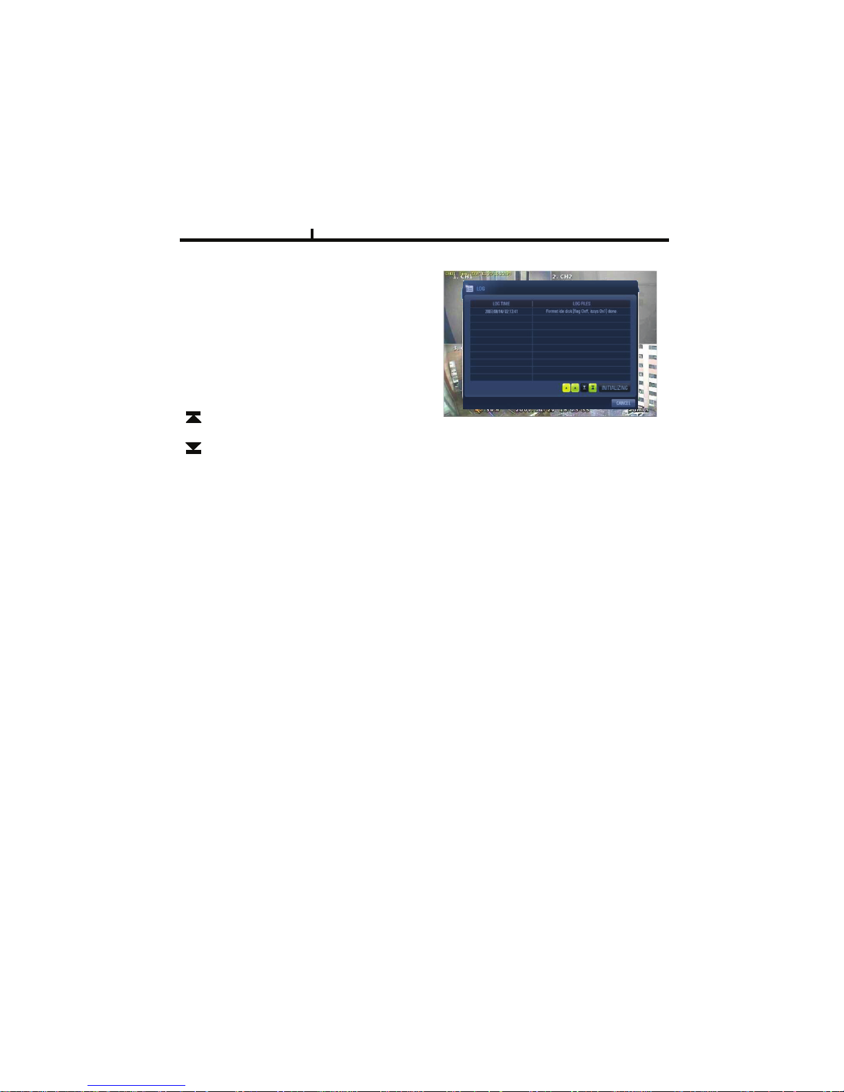
LOG
LOG
Shows all log infos on SYSTEM and other events
CLEAR : Remove all log info.
UP/DOWN button : Move to next/previous log info
page by page .
Move to first part of LOG info.
Move to Last part of LOG info.
LOGOUT
LOGOUT function when exiting set up
SYSTEM SHUTDOWN
SYSTEM ends.
The same as POWER OFF button of front or remote control.
Chapter IV
Page 37
37
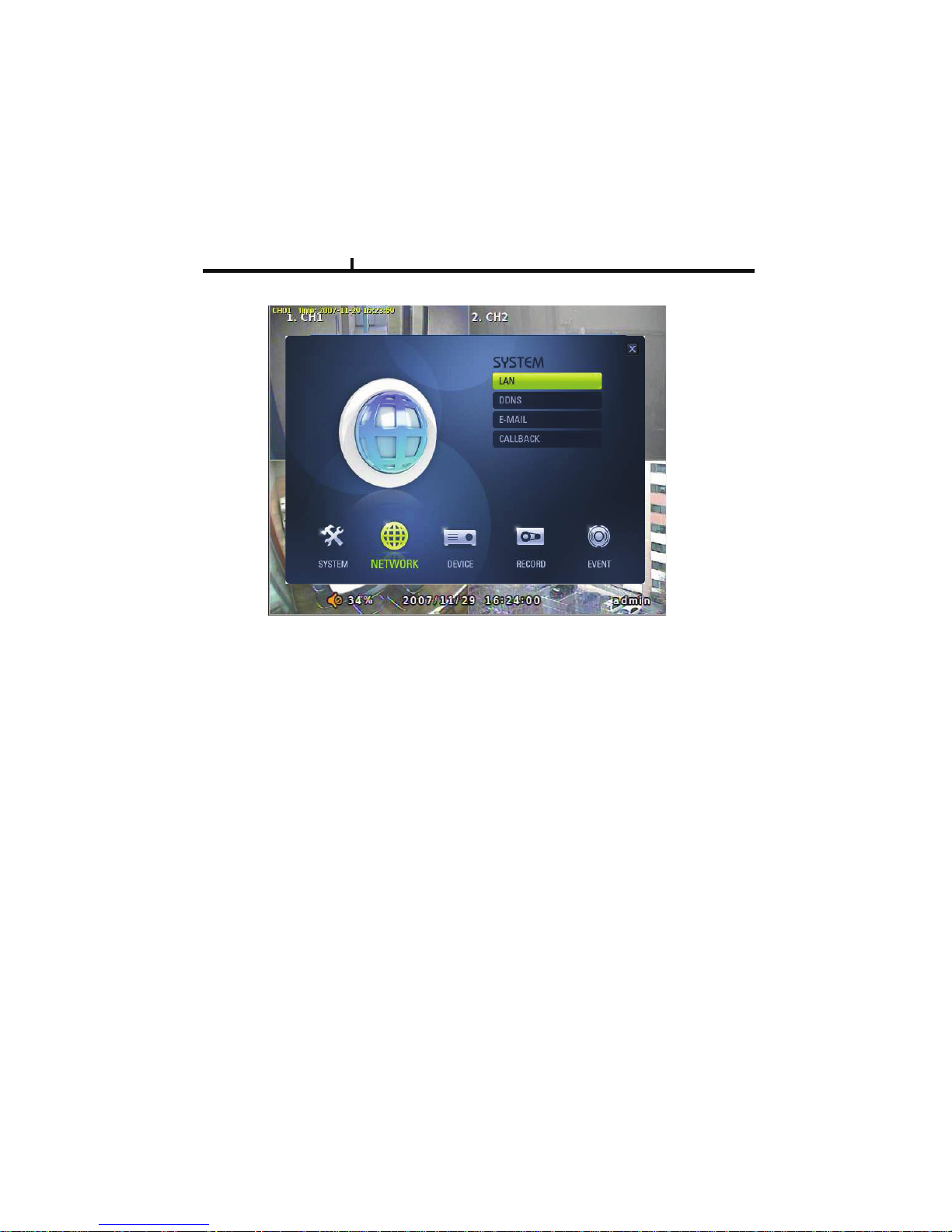
NETWORK
Set up various NETWORK items
LAN
DDNS
E-MAIL
CALLBACK
NETWORK
Chapter IV
Page 38
38
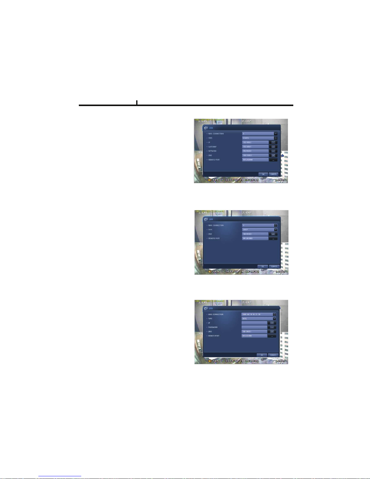
LAN
STATIC TYPE
Select in case of STATIC IP.
All setting values of IP, GATEWAY, NETMASK
Need to be set manually.
MAX CONNECTION
Shows maximum numbers of
Connectable users.
(Up to 4)
DHCP TYPE
Select during automatic DHCP IP.
User set DNS only.
(under the situation of DHCP server operating mode)
ADSL TYPE
In case USER ID, P/W are needed to input
such as PPPoE of ADSL line
Chapter IV
Page 39
39
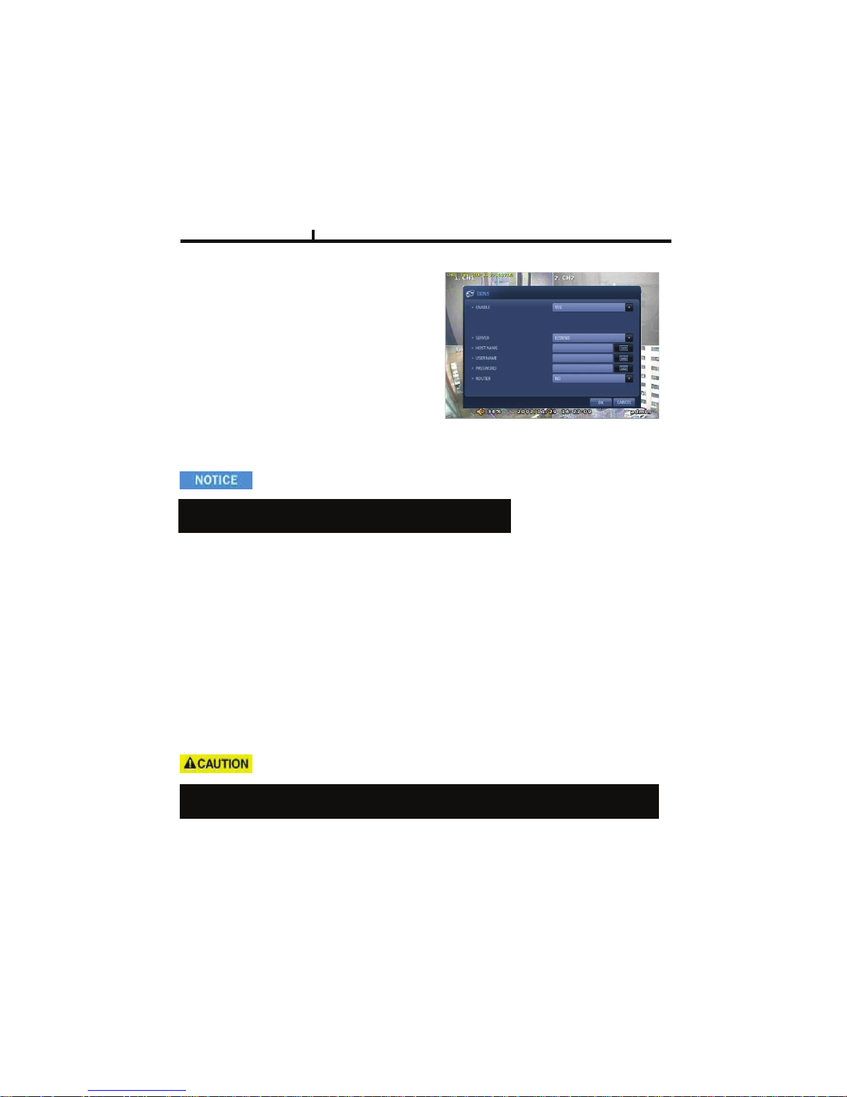
DDNS(DYNAMIC DNS)
ENABLE
Select if you want DDNS
This is under the situation of Dynamic IP
Network.
SERVER
Select DDNS server
EZDDNS : Specialized DDNS server operated by Manufacturer
Î www.ezddns.com
DYNDNS: DDNS common server
Recommended to use EZDDNS Server rather than DYNDNS as DYNDNS is not optimized
The system.
In order to use DDNS service
Account & HOSTNAME should be registered in the server first.
HOSTNAME
User name of IP ADDRESS ON Dynamic IP circumstance.
It is the same name as registered on DDNS server.
USERNAME / PASSWORD
Type the user name & pas word registered on DDNS service.
ROUTER
Check if NETWORK is through ROUTER or IP sharer .
Chapter IV
Page 40
40
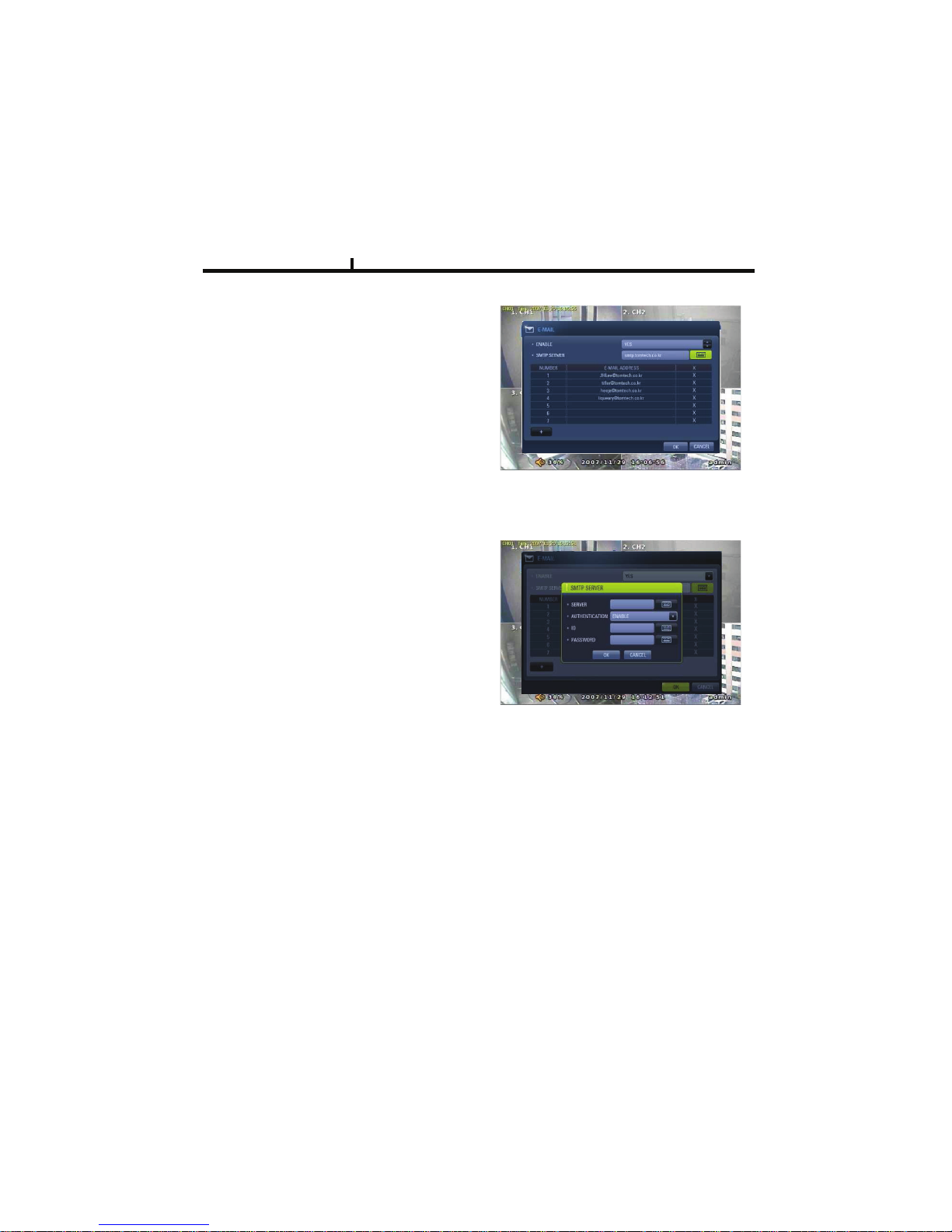
E-MAIL
ENABLE
Select when you need E-MAIL transmission.
ALL event information is sent to admin’s
E-mails.
SMTP SERVER
Write the MAIL sending SMTP server name.
AUTH ENABLE
Check when you need account
authority.
ID / PASSWORD
Input account & password .
Chapter IV
SENDER
Write the mail account of sender.
Page 41
41
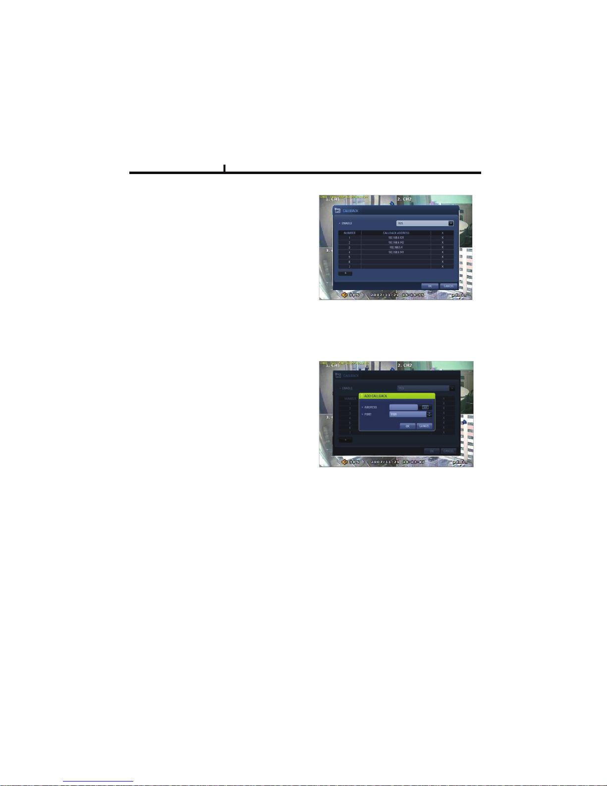
CALLBACK
ENABLE
Check to use CALLBACK function .
All event or specific information are sent to
“Agent” Program which is installed on P.C
CALLBACK ADD
Register IP address of P.C for callback
function
Chapter IV
Page 42
42
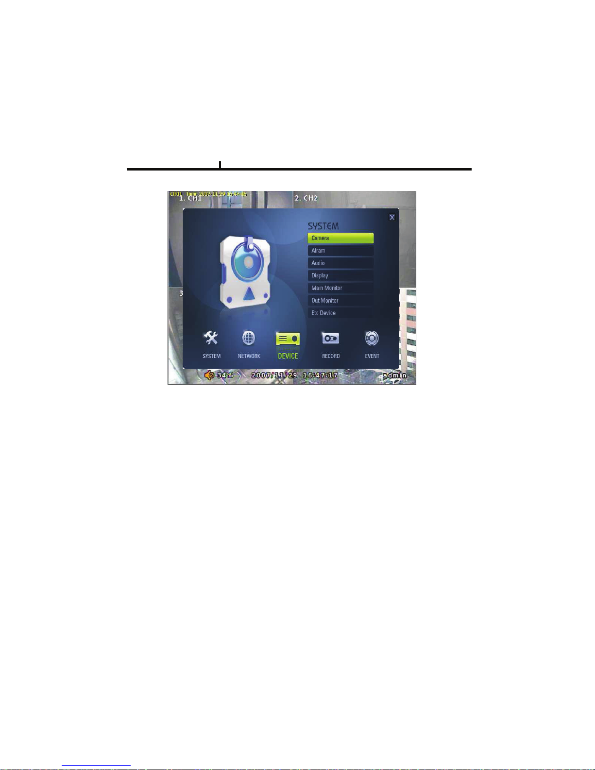
DEVICE
DEVICE
These are item lists for the control of CAMERA, ALARM .
CAMERA
ALARM
DISPLAY
MAIN MONITOR
SPOT MONITOR
MISCELLANEOUS
Chapter IV
Page 43
43
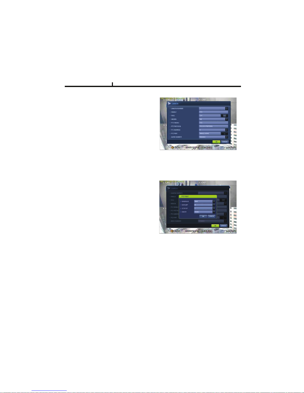
CAMERA
ENABLE
Check if you want to use current camera
TITLE
Can change the camera name.
HIDDEN
Doesn’t show the screen on live mode
Even though it records and runs normally.
PTZ ENABLE
Check if you want to use PTZ function.
PTZ PROTOCOL
Select PTZ PROTOCOL.
Various of protocol information including
PELCO-D are implemented.
If you can not find one, please contact manufacturer
PTZ ADDRESS
When you use many of same PTZ equipments
You can name on these PTZ sites.
Site numbers can be from 0 to 255.
PTZ PORT
Adjustable related protocol BAUDRATE, DATA BIT.
Chapter IV
Page 44
44
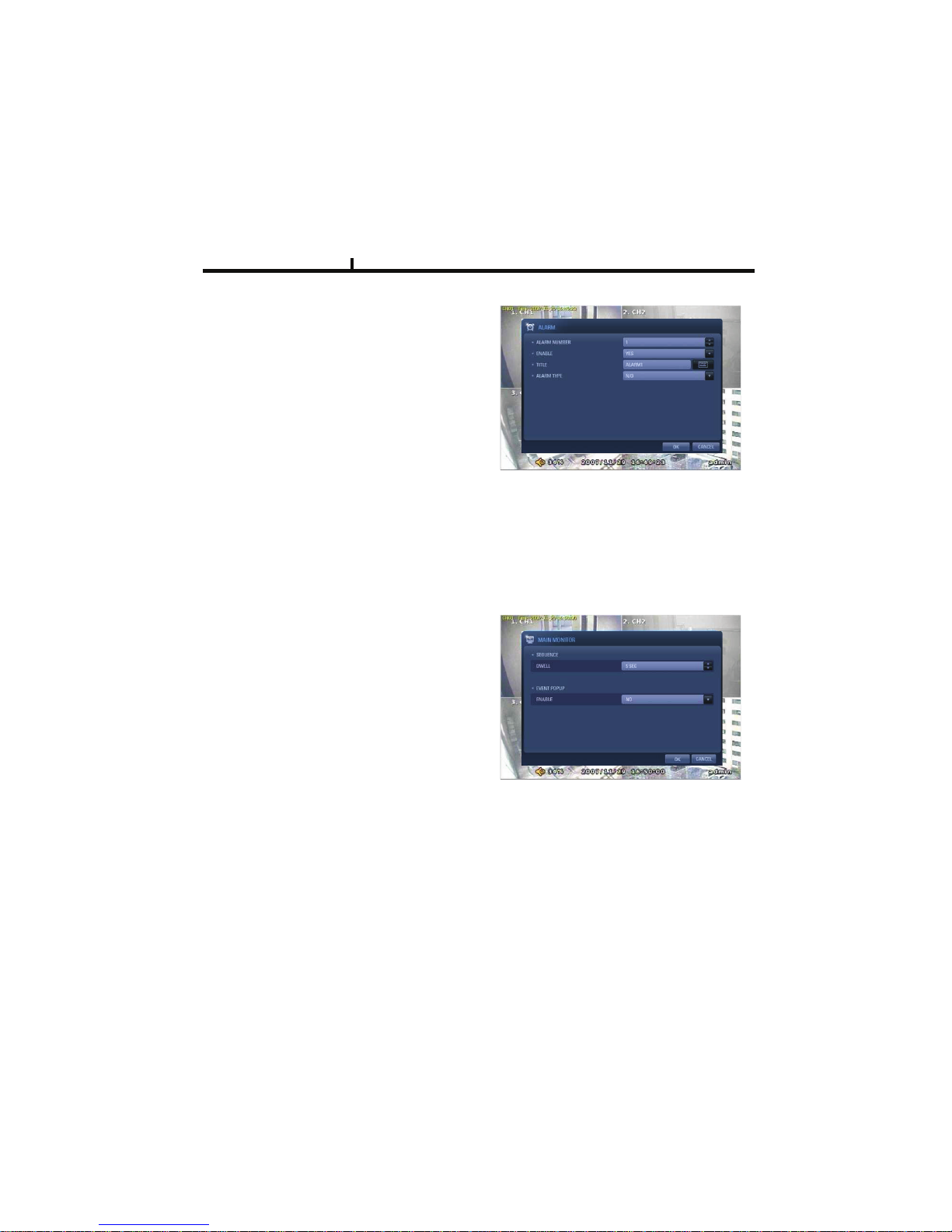
ALARM
ENABLE
Check if you use specific ALARM.
TITLE
Changes connected ALARM names.
ALARM TYPE
Select specific ALARM TYPE.
(NORMAL OPEN, NORMAL CLOSE)
MAIN MONITOR
Set up SEQUENCE, EVENT POPUP
of main monitor.
SEQUENCE
Set up the screen switching times.
EVENT POPUP
Check if you want event pop up function.
Chapter IV
Page 45
45
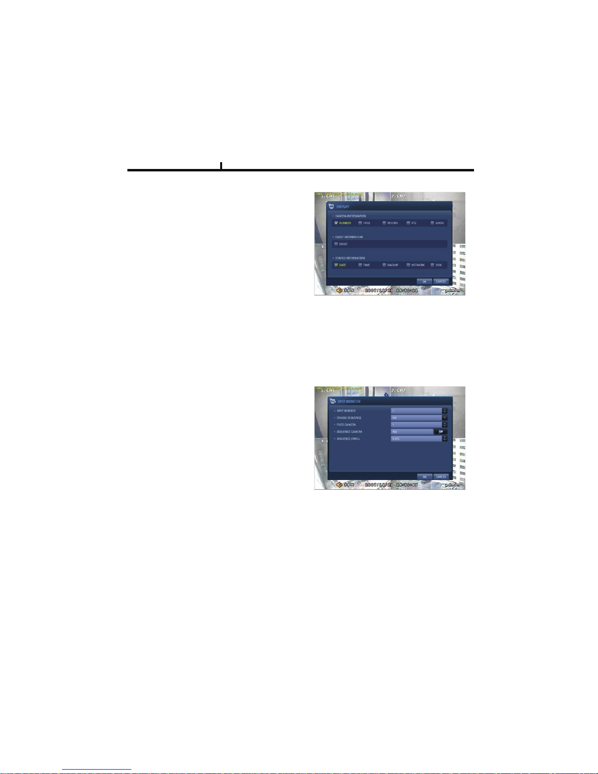
DISPLAY
Shows all OSD display details.
CAMERA INFOMATION
Selects the display of CAMERA NO, TITLE
EVENT INFOMATION
Select OSD display for the EVENT.
STATUS INFORMATION
Shows various status of OSD.
SPOT MONITOR
Set up functions of SPOT MONITOR.
SPOT NUMBER
Select SPOT output numbers.
SPOT SEQUENCE ENABLE
Select SPOT switching channel.
FIXED CAMERA
Select the camera number not to switch .
SEQUENCE CAMERA
Select which camera to switch.
SEQUENCE DWELL
Adjust switching times .
Chapter IV
Page 46
46
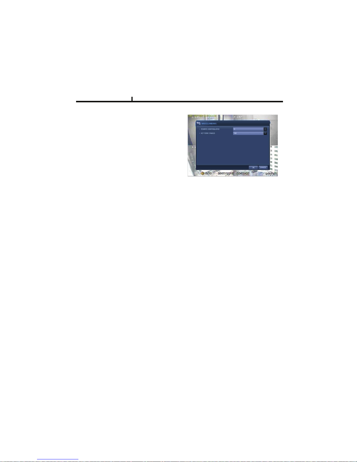
MISCELLANEOUS
Control of remote controller/key related functions.
REMOTE CONTROLLER ID
Designate remote control ID.
It is useful when many DVRs installed
at the same place .
KEY TONE ENABLE
Select button volume on the front panel.
Chapter IV
Page 47
47
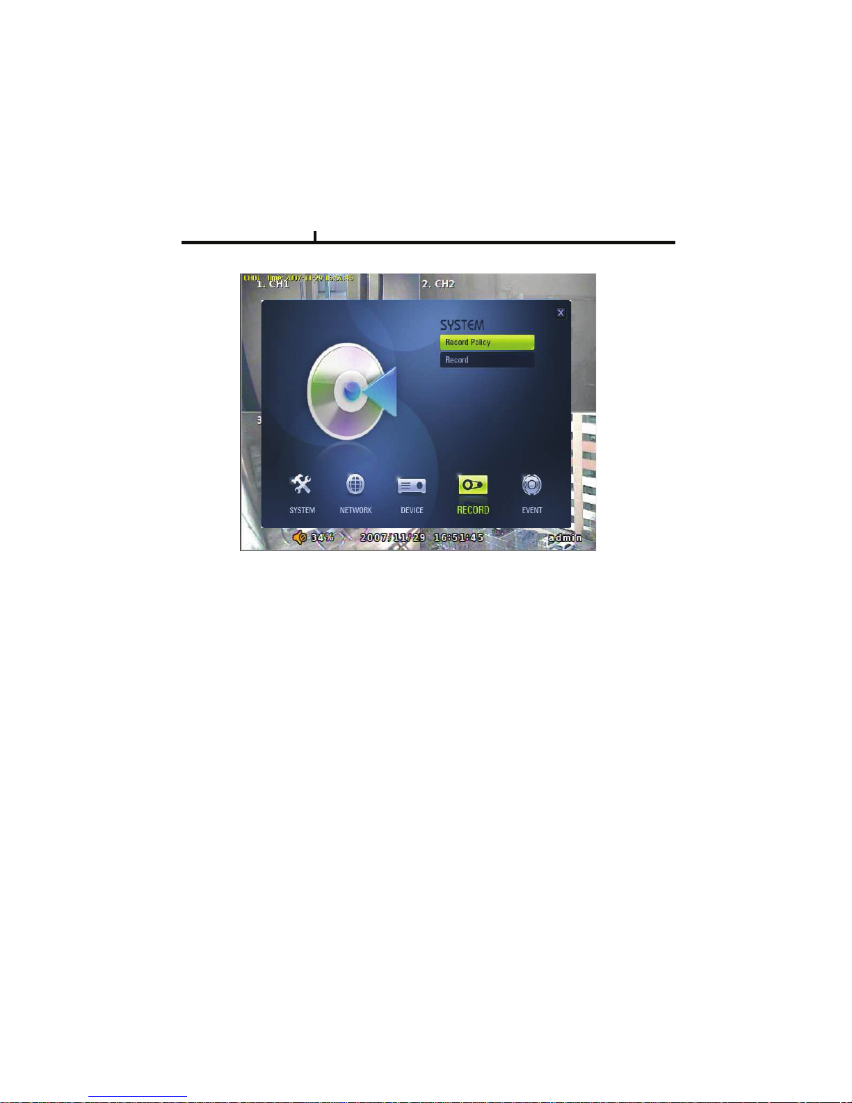
RECORD
These are control lists of recording related functions.
RECORD POLICY
RECORD
RECORD
Chapter IV
Page 48
48
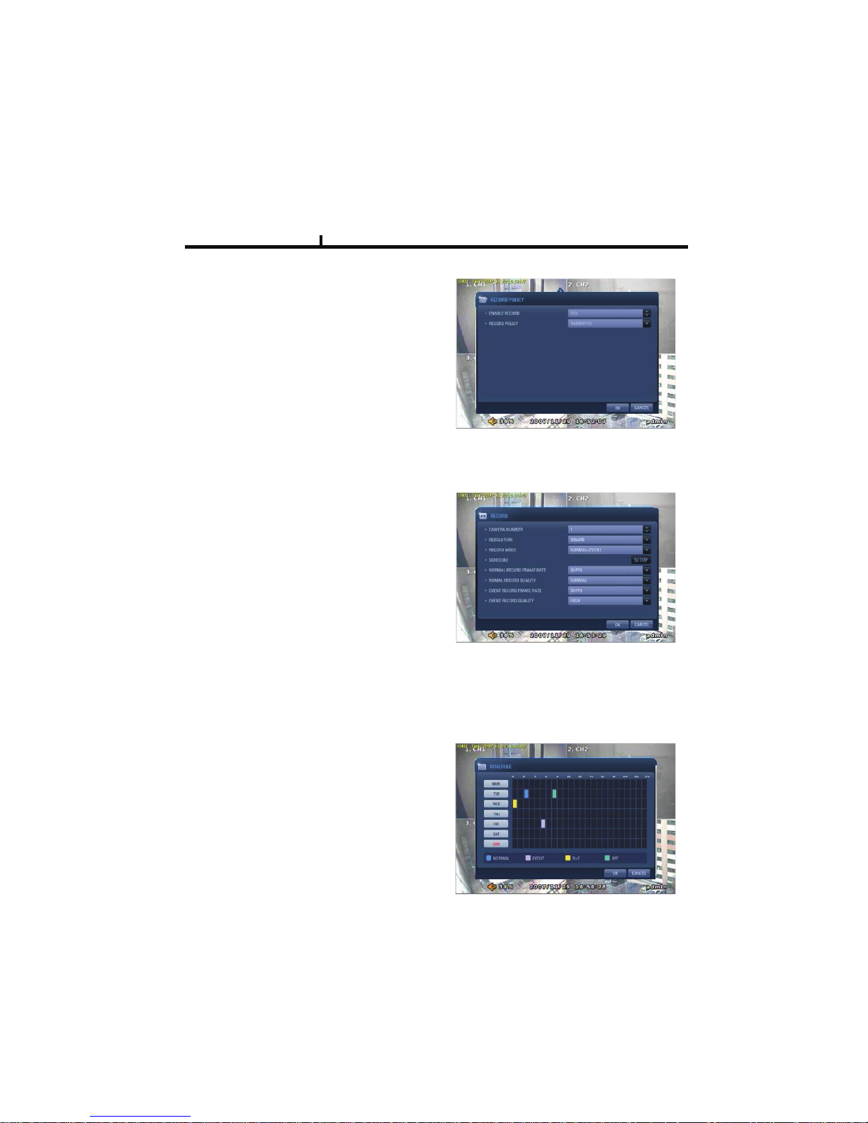
RECORD POLICY
Select RECORD types.
- Two types (Single Record, Overwrite)
RECORD
Set up specific record type per each camera.
RESOLUTION
Set up resolution.
-360*240(CIF)
-720*240(HALF-D1)
-720*480(D1)
RECORD MODE
Set up record type.
NORMAL+EVENT is focused record mode.
NORMAL/EVENT RECORD FPS
Set up how many frames to record.
NORMAL/EVENT RECORD QUALITY
Set up record quality.
SCHEDULE
Set each week’s schedule.
Chapter IV
Page 49
49
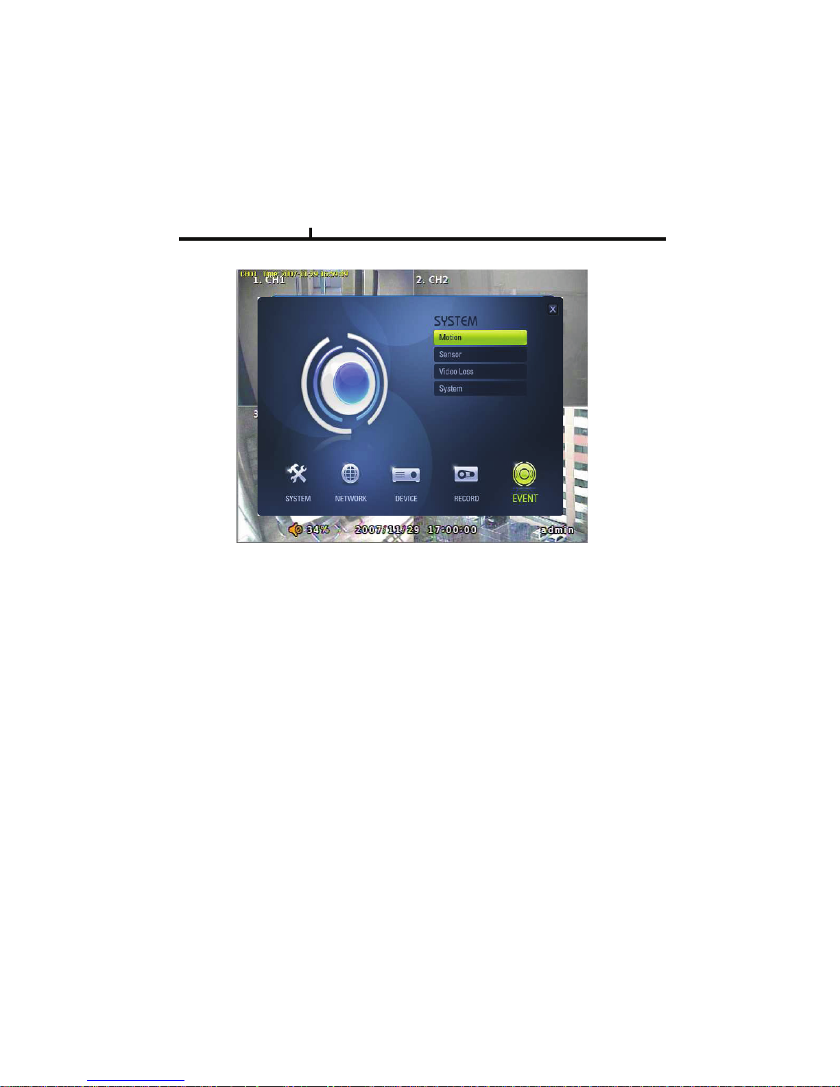
EVENT
EVENT
This is for the control of all event items such as MOTION, SENSOR.
MOTION
SENSOR
VIDEO LOSS
SYSTEM
Chapter IV
Page 50
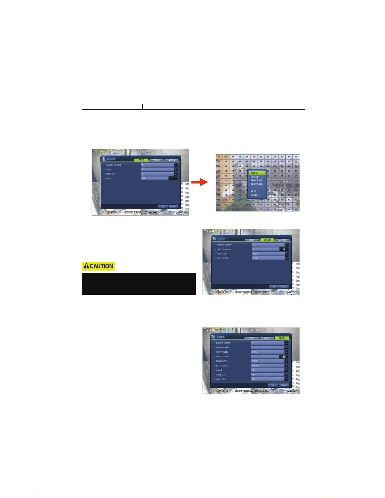
50
MOTION
SETUP
Set up the MOTION area & sensor.
Click mouse right or MENU KEY button
to see motion area window
RECORD
Set pre& post record mode.
ACTION
Setting up list for how to act after EVENT.
- POPUP CAMERA/DWELL
:Set popup channel & time.
- ALARM/BUZZER DWELL
:Set alarm & buzzer time.
- E-MAIL
:Select EVENT info to be sent by e-mail.
- CALLBACK
:Select EVENT info to be sent to AGENT.
- WRITE LOG
:Select to write LOG info.
When record frames are less, PRE/POST
RECORD need to be set a lot more for
correct record search.
Chapter IV
Page 51
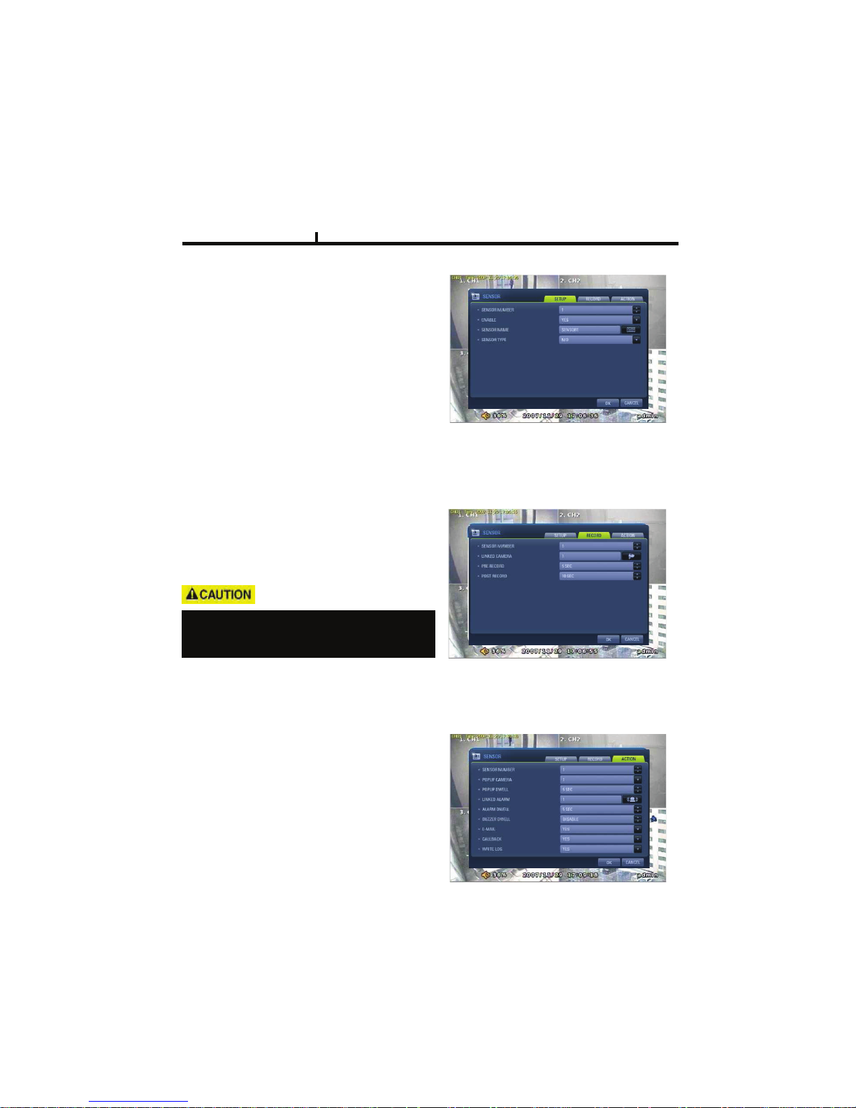
51
SENSOR
SETUP
Set the SENSOR name & TYPE.
NORMAL OPEN : Normally it opens
and sends signals when detects sensors.
NORMAL CLOSE : Normally it closes,
and it sends SIGNAL when detects sensors.
RECORD
Set Connecting camera,
Pre, post record.
ACTION
Setting up list for how to act after EVENT.
- POPUP CAMERA/DWELL
:Set popup channel & time.
- ALARM/BUZZER DWELL
:Set alarm & buzzer time.
- E-MAIL
:Select EVENT info to be sent by e-mail.
- CALLBACK
:Select EVENT info to be sent to AGENT.
- WRITE LOG
:Select to write LOG info.
Chapter IV
When record frames are less, PRE/POST
RECORD need to be set a lot more for
correct record search.
Page 52
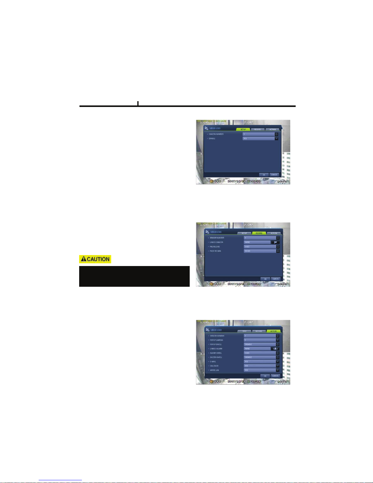
52
VIDEO LOSS
VIDEO LOSS can be an event type and
can set camera record and action.
RECORD
Set connecting camera Pre& post record.
SETUP
Select whether you want VIDEO LOSS
Function or not.
Chapter IV
ACTION
Setting up list for how to act after EVENT.
- POPUP CAMERA/DWELL
:Set popup channel & time.
- ALARM/BUZZER DWELL
:Set alarm & buzzer time.
- E-MAIL
:Select EVENT info to be sent by e-mail.
- CALLBACK
:Select EVENT info to be sent to AGENT.
- WRITE LOG
:Select to write LOG info.
When record frames are less, PRE/POST
RECORD need to be set a lot more for
correct record search.
Page 53
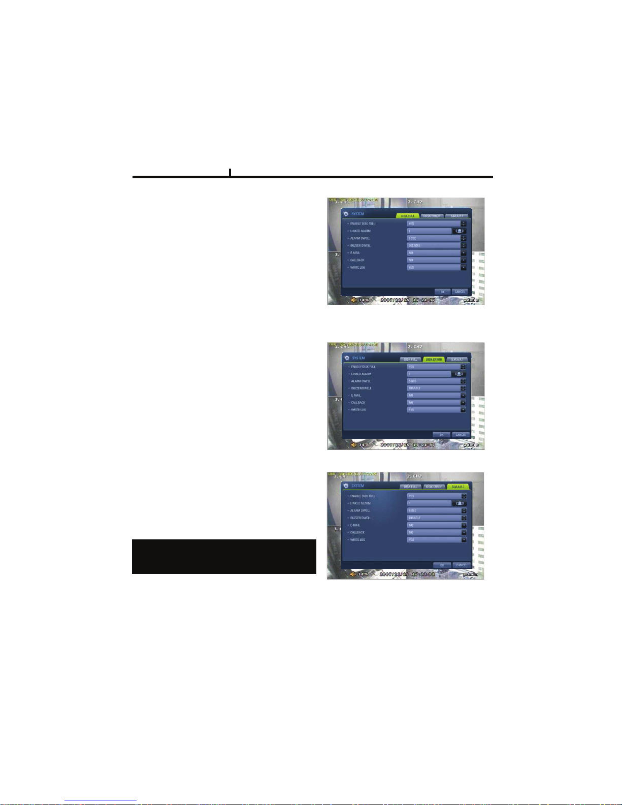
53
SYSTEM
Sets how to operate event related with
DISK mainly.
DISK FULL
Sets when HDD is full of record.
S.M.A.R.T
Enables the system to prevent possible
malfunction of HDD by interfacing
between system and HDD.
Chapter IV
If you found “BAD HDD” mark in the
S.M.A.R.T function, please exchange HDD as
soon as possible
DISK ERROR
Sets when there is an error on HDD.
Page 54

54
Chapter-V. SEARCH
Page 55
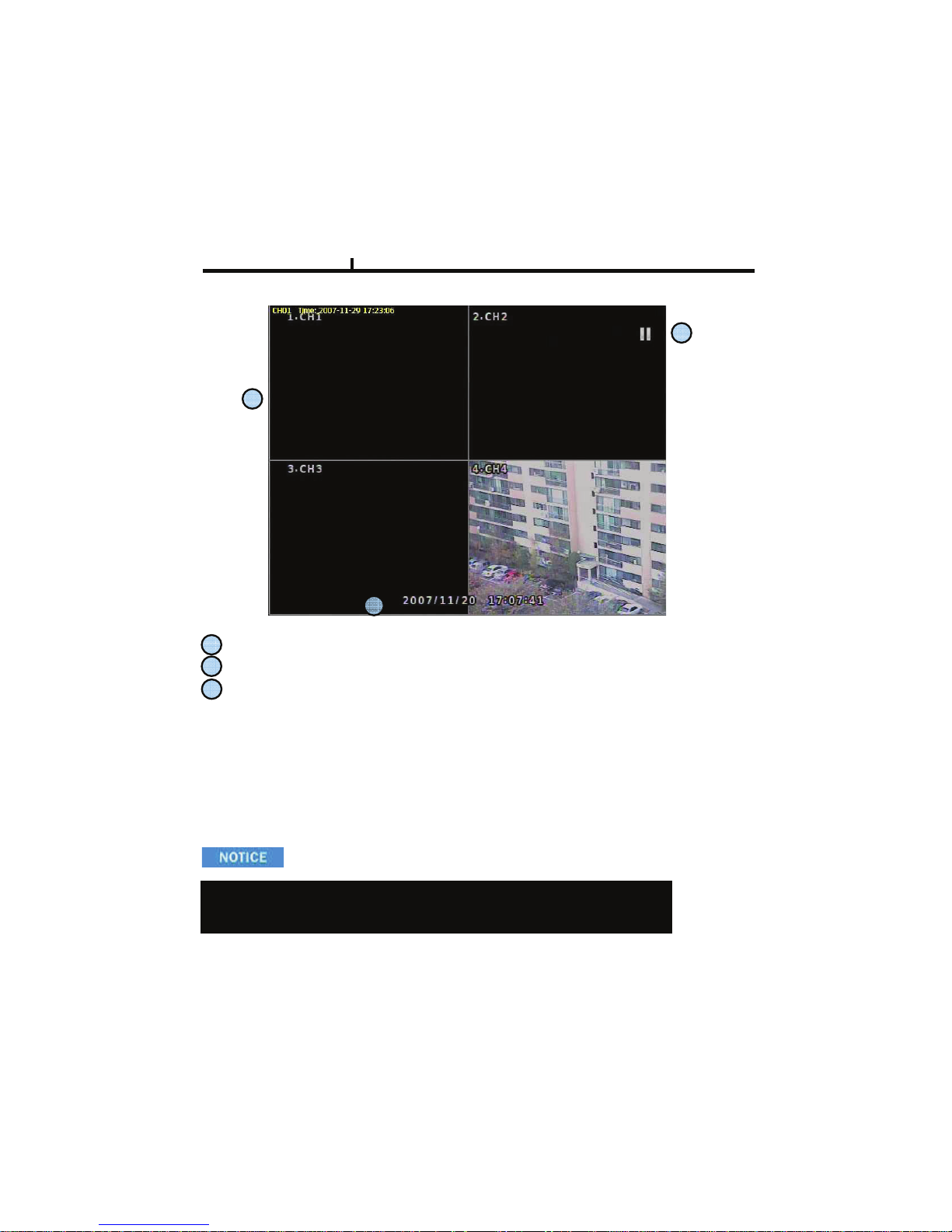
55
Playback Screen : Record Playback
Playback Time : Playback Time Display
Display Status
Playback Icon
Pause ( )
Playback (!)
Multiple Playback(; ;, ; ; ;, ; ; ; ;)
1
2
1
2
3
3
SEARCH
It randomly shows the first searched record file when it goes to SEARCH MODE.
This type is the same as on event search , so it is possibly not to shows
The exact record file searched .
Chapter V
Page 56
56
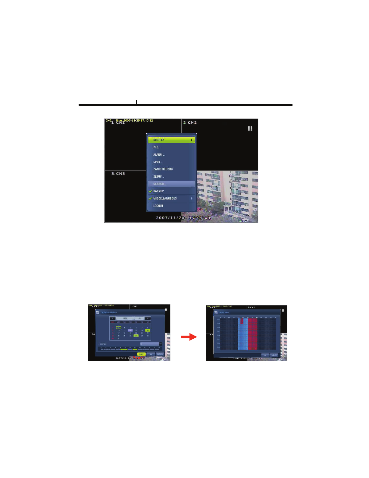
DISPLAY
Select screen division mode. (1,4 spirit)
CALENDAR SEARCH
Select date , hour, minutes, seconds in turn on calendar search.
When you click MINUTE, you can find specific record status as right below.
SEARCH MENU
Chapter V
Page 57
57
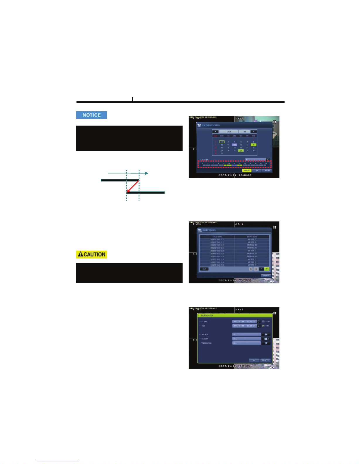
EVENT SEARCH
It shows all EVENT record list.
If you click related EVENT,
It plays that event promptly.
SEARCH KEY
Can be selectable on EVENT search.
-START/END
:Set EVENT search start, end time.
-MOTION/SENSOR/VIDEO LOSS
:Selectable per each camera
Chapter V
It may not be the same channel image as
shown on EVENT LIST because it shows the
first display image recorded at that time zone.
Section is
Generated and maintained recording data that
occurs duplicating data returning previous time by
any cause during DVR operating
Section#1:
Sectoin#2:
Time progress
Page 58
58
FIRST
Move to first part of recorded DATA.
LAST
Move to last part of recorded DATA.
BOOKMARK
Sets automatically starting time during back up.
It is useful to set a bookmark as starting time
while search the data.
Chapter V
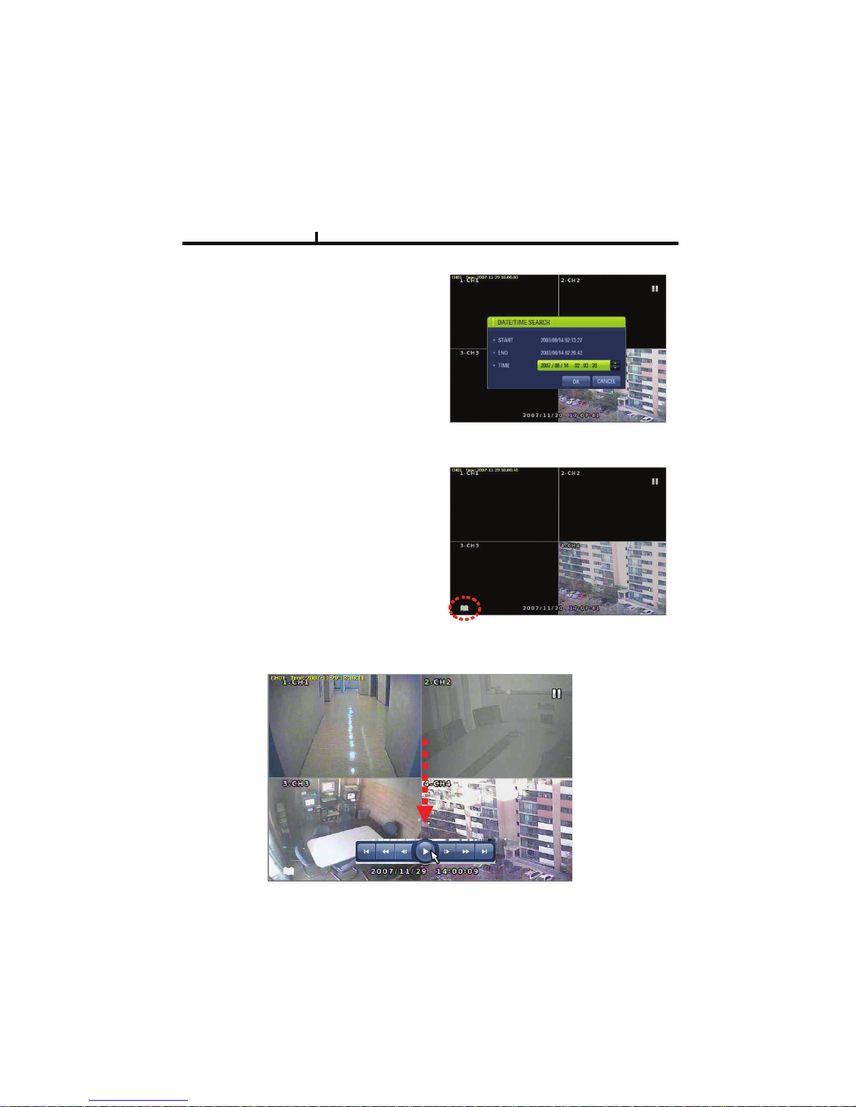
PLAYBACK USER INERFACE
Playback buttons appears when locate the mouse pointer at the bottom of screen
DATE/TIME SEARCH
Search data by Date/Time .
You can search the event promptly
When you know the exact event time.
Page 59
59
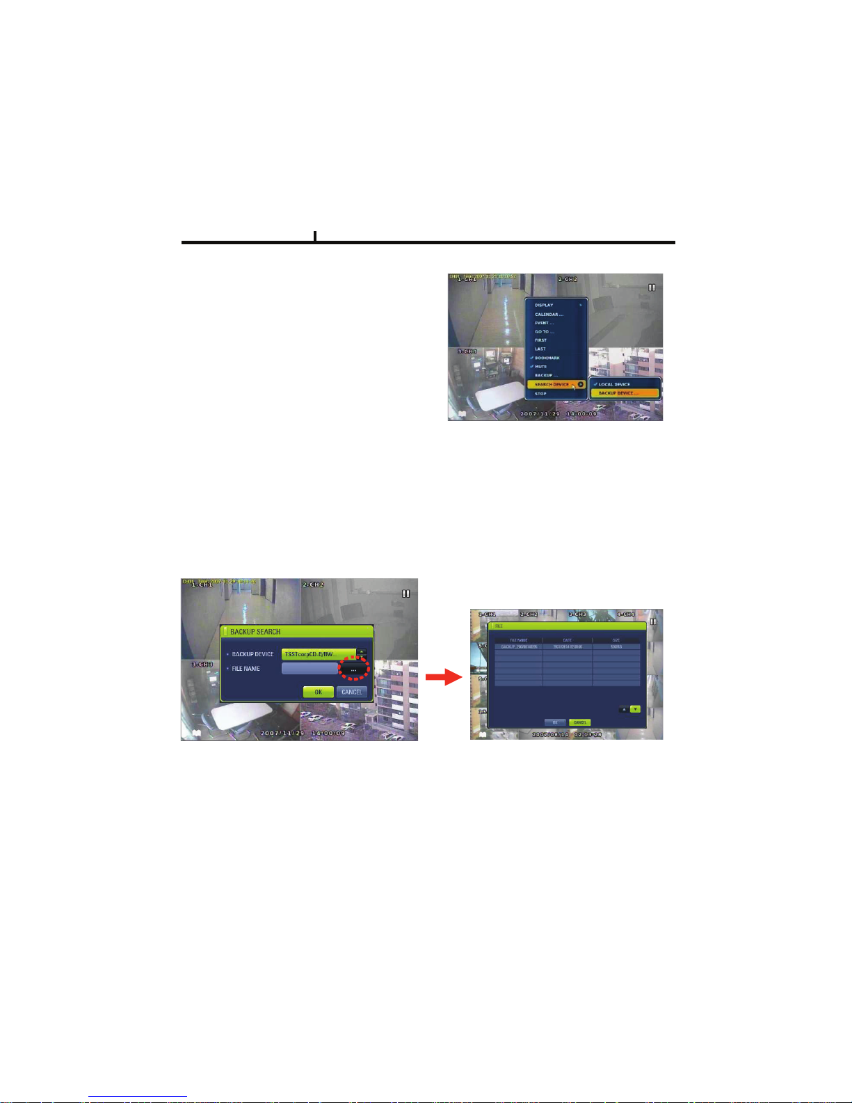
LOCAL DEVICE
Search the data of internal DISK.
BACKUP DEVICE
Search backup device (Select when you play the backup data.)
If there are various back up devices , you can select a specific one .
DEVICE
Search internal or external
SYSTEM DISK .
Chapter V
Page 60

Chapter-VI. Client program
60
Page 61
Chapter VI
1
4
2
3
5
6
10
8 9
7
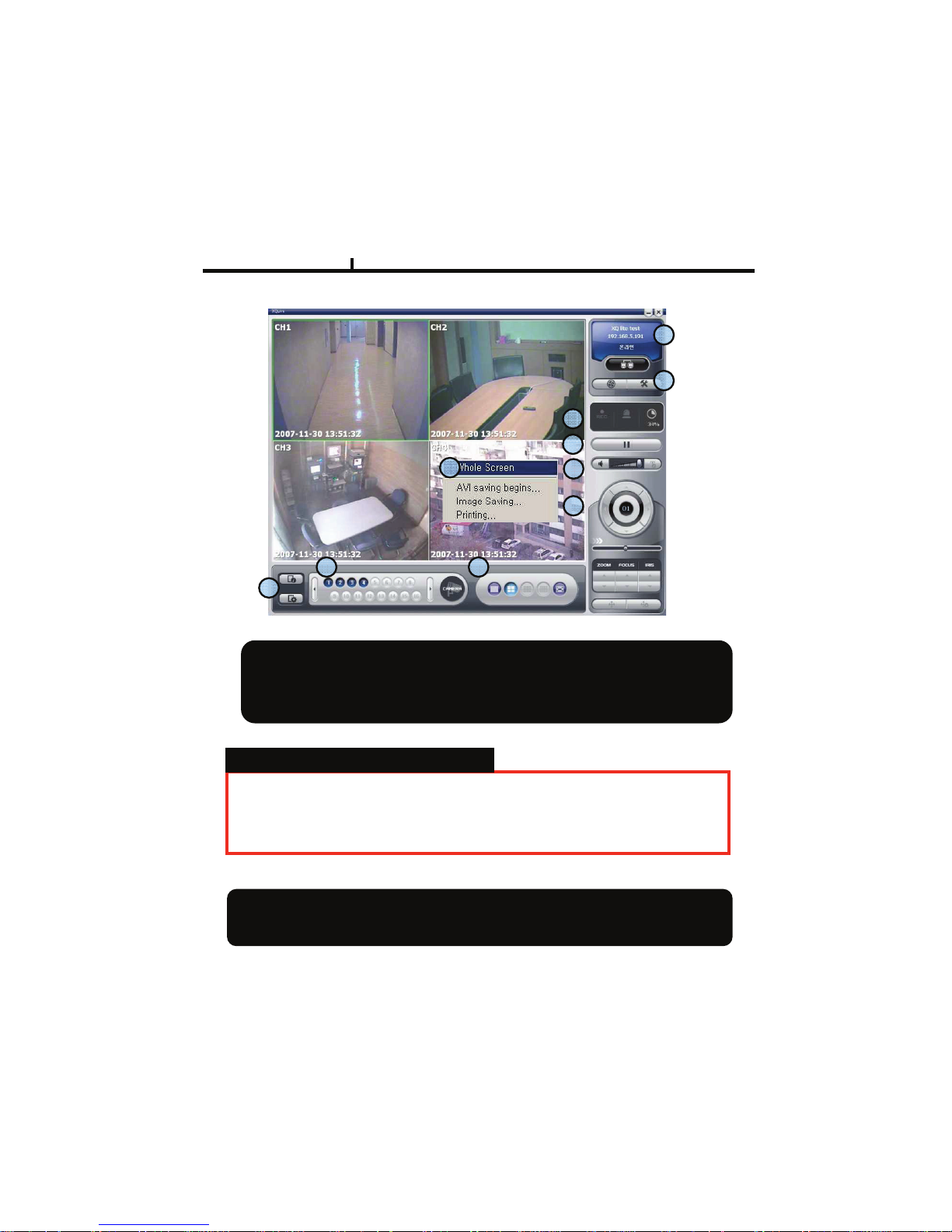
REMOTE
<REMOTE PROGRAM IS?>
With connected to DVR remotely, it is to perform Remote Monitoring, Remote
Search, Remote Backup etc. (Please install remote program from the program
CD)
61
Environment conditions for Remote Program
1. INTEL P-4
2. 256M or higher main memory(512M recommend)
3. WINDOWS O/S(WIN 2000, XP, Vista(32bit))
4. 32MB VGA card supports RGB (ATI series recommend)
5. At least 10Mbps network speed (Max 100Mbps support)
Please note that some buttons and graphics may not be activated at this moment.
Those inactivated buttons will be used later when system upgrades and expands
Page 62
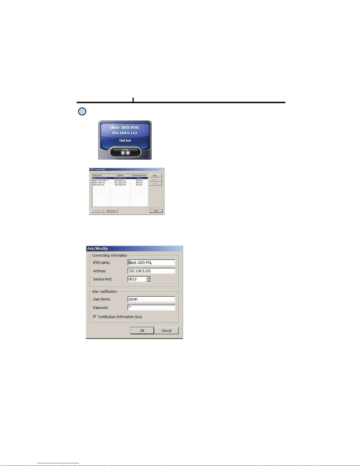
<New Connection/Modify Dialogue Window>
DVR name :
Specify a name that you can easily
identify.
Address :
Specify assigned IP address to
connect DVR (Type the Host name of
REAL IP or DDNS.)
1
Connection information and Button
Shows DVR’s name, IP address and connection status.
DVR connection button.
<DVR Connection Window>
Add
Modify
Delete
: Enter IP address and user authentication
to connect DVR
: Modify IP address and user authentication
of the existing list
: Delete existing use.
Chapter VI
62
Page 63
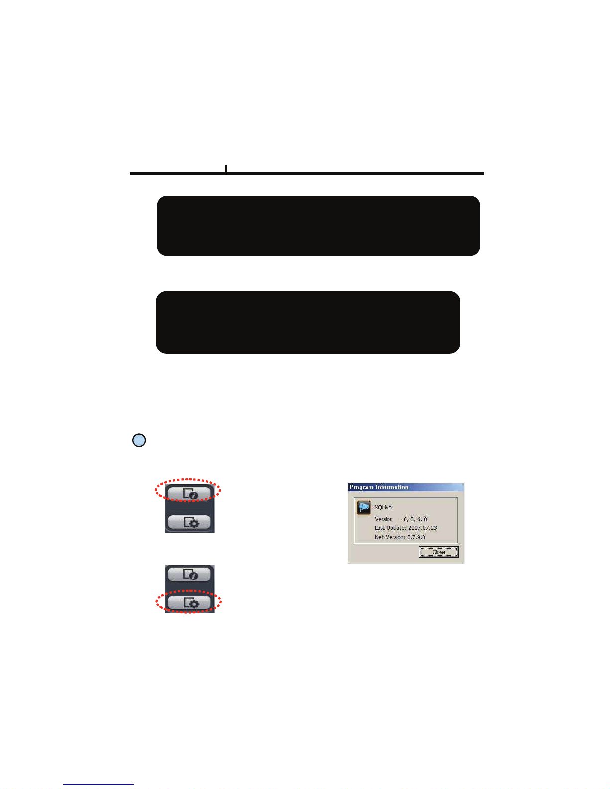
2
Program Information :
Shows Remote Program’s
information.
Program Setup :
Sets up Remote Program.
( Language, Display Output, Resolution, Save Path, Network
Speed Etc)
<Program Information Window>
<What is IP address?>
A set of address system that is used to find out destination in network access via
Internet or LAN.
IP address is divided into REAL IP and VIRTUAL IP, and REAL IP must be sent on
DVR for the access from remote site via internet. You can be assigned with REAL IP
Or DDNS service ID (Hostname of Dynamic Domain Name Server).
Service Port :Set this the same as the service port assigned to DVR.
<What is service port?>
Function to make the virtual IP available to the devices such PC or DVR with
Automatic connection to the specified service port when remote access is made
To router via the router or IP Share of one REAL IP. (But this function is available
Only when router or IP Share supports it.)
User Name : Type the user name authorized in DVR
Password : Type the password authorized in DVR
Save Authentication Information :Save Authentication Information
Chapter VI
Program Information and Set up
63
Page 64
3
Status Icon
Status icon of connected DVR
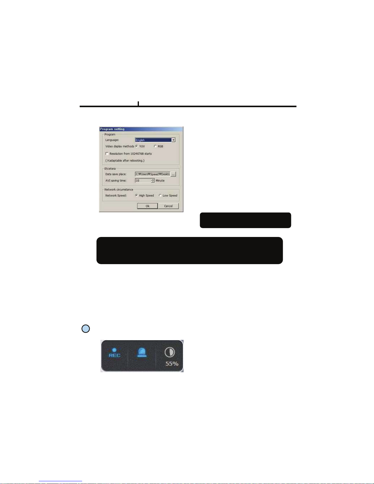
Language :
To choose program’s language.
Video Display :
YUV mode : According to your PC
graphic card ability, the support can be
decided. This mode shows faster,
clear ability of image transmission than
RGB mode.
RGB mode : It is widely compatible
with most graphic cards, and select
this when YUV mode is not supported..
Resolution from 1024X768 starts :
It always shows 1024 x768 when you
check..
<Program Setup Window>
<<<< Above setting value will apply after
restart of the program.
Data Save Place :Sets ups basic path of AVI file to save.
AVI Saving time : Sets up saving time of AVI file from remote.
Network Speed :
High Speed : System sends off images at high speed possible.
Low Speed : System sends off images at normal speed in consideration of stability.
<Recommended Graphic Card>
ATI series : Radeon7000series (More then 32M), RADEON series…
NVIDIA series : M64series(More then 32M), GEFORCE series…
Etc : VGA card to support YUV mode YUV…
Chapter VI
64
Page 65
65
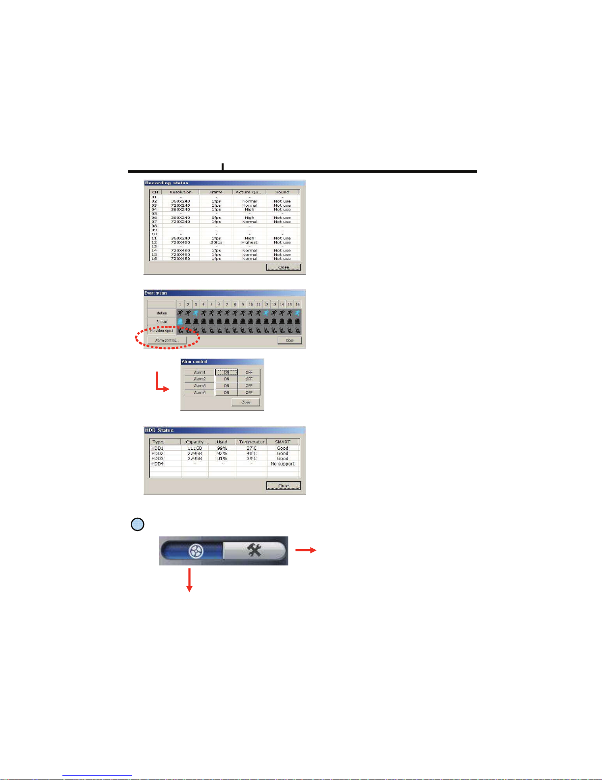
<Event Status>
<HDD Status>
Shows DVR’s event status and you can
check the status of Motion, Sensor,
Video Loss at real time.
<Alarm Control>
You can On/Off the DVR’s alarm if you press
the Alarm control button.
Shows the connected DVR HDD status.
You can check temperature and status
at real time.
<Recording Status>
Shows and check the recording status
4
REMOTE SEARCH Execution and Set Up
REMOTE SEARCH Execution
Set Up Execution
Pressing each button operates
REMOTE SEARCH or Set Up.
REMOTE (LIVE) and REMOTE
SEARCH are made up in separate
program.
Chapter VI
Page 66
Remote Set Up <Camera>
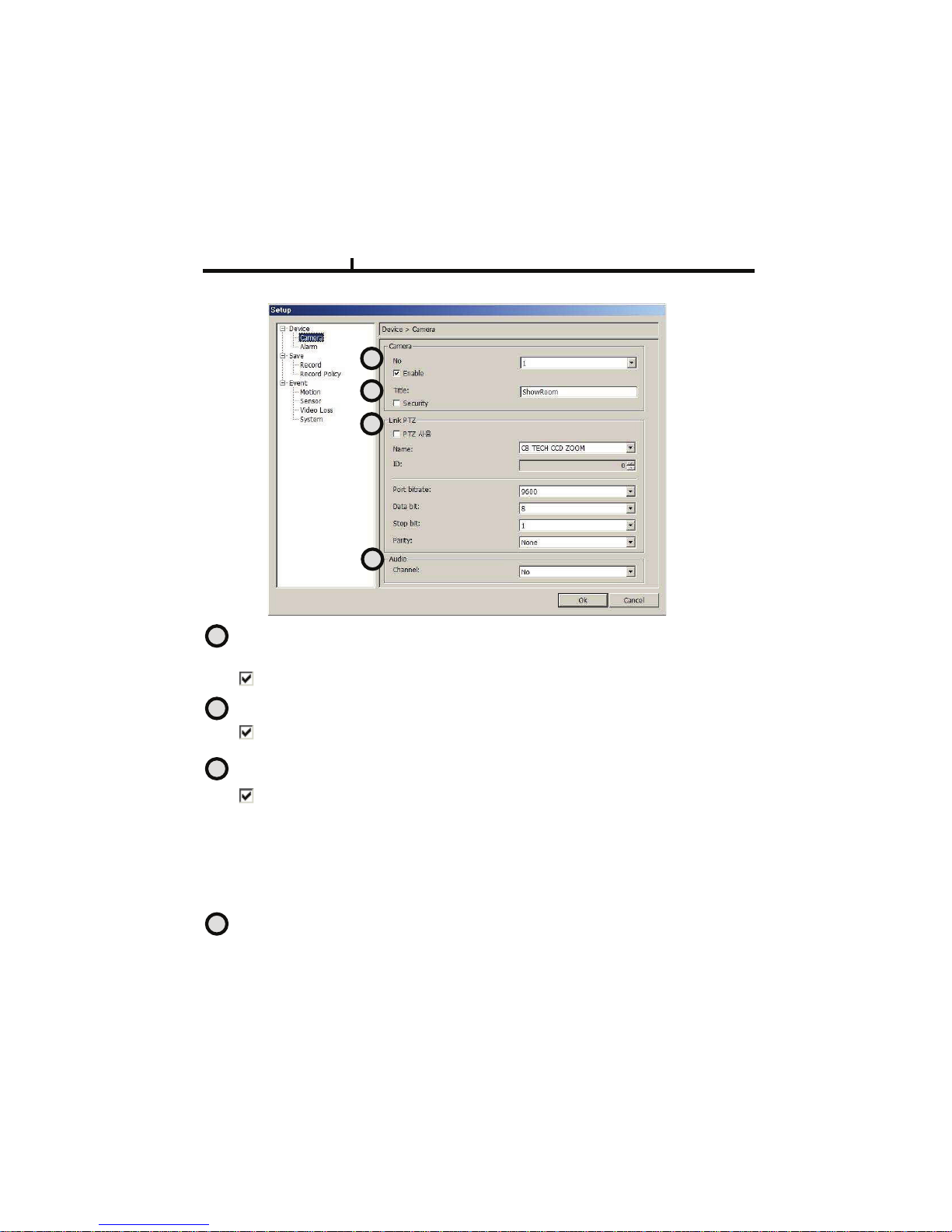
Enable : Selection item to use camera, Removing the check stops using that channel.
No : Item to select camera No
To set up all the camera equally, Choose “select all”
Security : When checked, It displays ‘Hidden’ on monitor. (though it keeps recording)
Title : Item to revise/type the camera name.
PTZ address: Item to assign PAN TILT address per camera.
Name :Item to check PTZ Camera’s model name.
ID : Item to select PTZ address per camera.
Port bit rate : Item to select the PTZ’s port bit rate.
Data bit :Item to select data bit.
Stop bit : Item to select Stop bit.
Parity : Item to select Parity.
Link PTZ : Sets up PTZ camera.
Audio : Item to select which audio channel to be used among total 4 audio inputs.
1
2
3
4
1
2
3
4
Chapter VI
66
Page 67
No : 8=>?#=.#@>A>B=#!AC/?#".D
&.#@>=#EF#CAA#=G>#BC?>/C#>HECAAIJ#3G..@>#“@>A>B=#CAA”
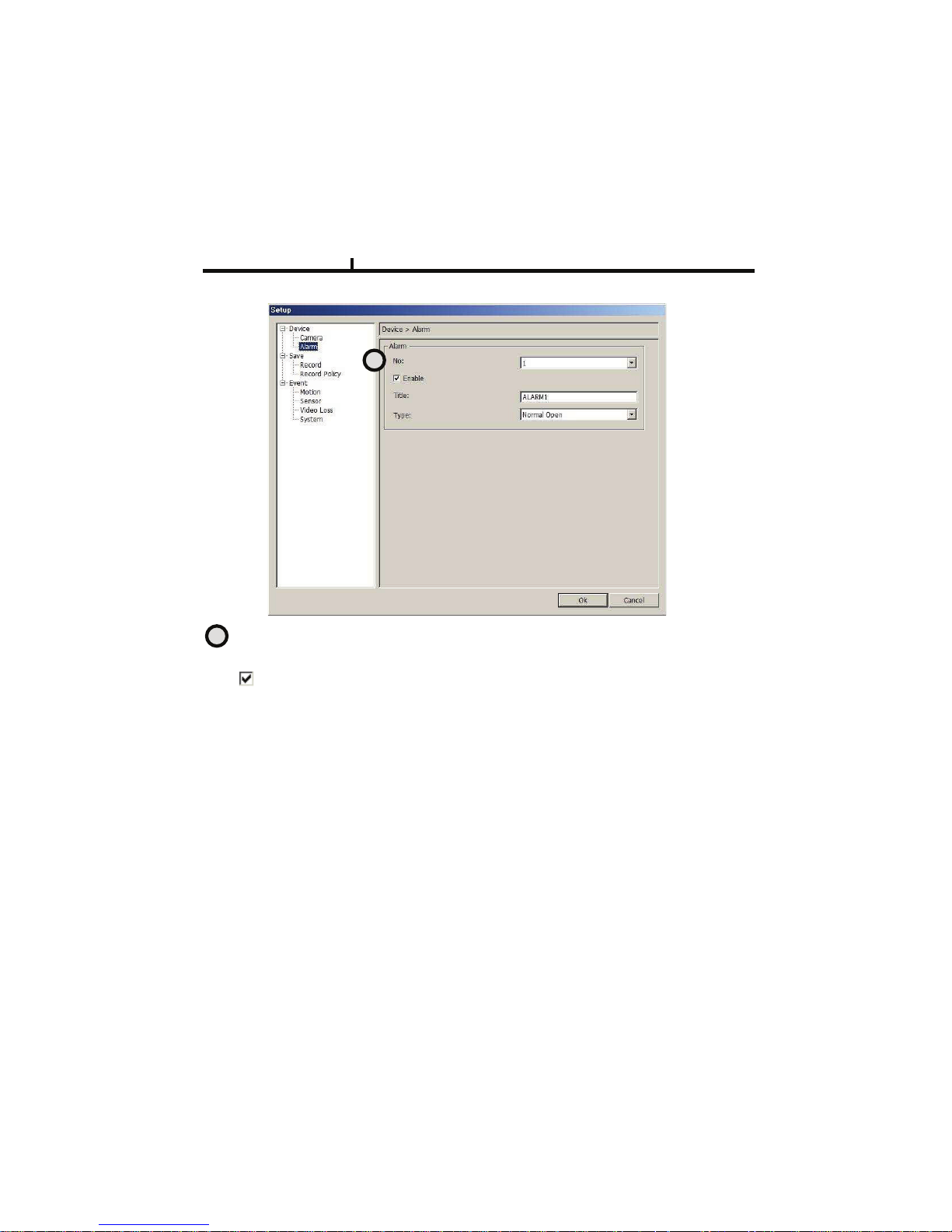
Enable : 8=>?#=.#@>A>B=#=.#E@>#!AC/?J#:>?.KLMN#=G>#BG>BO#@=.F@#E@LMN#=GC= BGCMM>AD
Title : Item to type Alarm’s name.
Type : Item to select Alarm’s type.
- Normal Open : Type of alarm open in general situation.
- Normal Close : &IF>#.P#CAC/?#BA.@>#LM#N>M>/CA#@L=EC=L.MD
1
1
Chapter VI
Remote Setup <Alarm>
67
Page 68
Remote Set Up <Record>
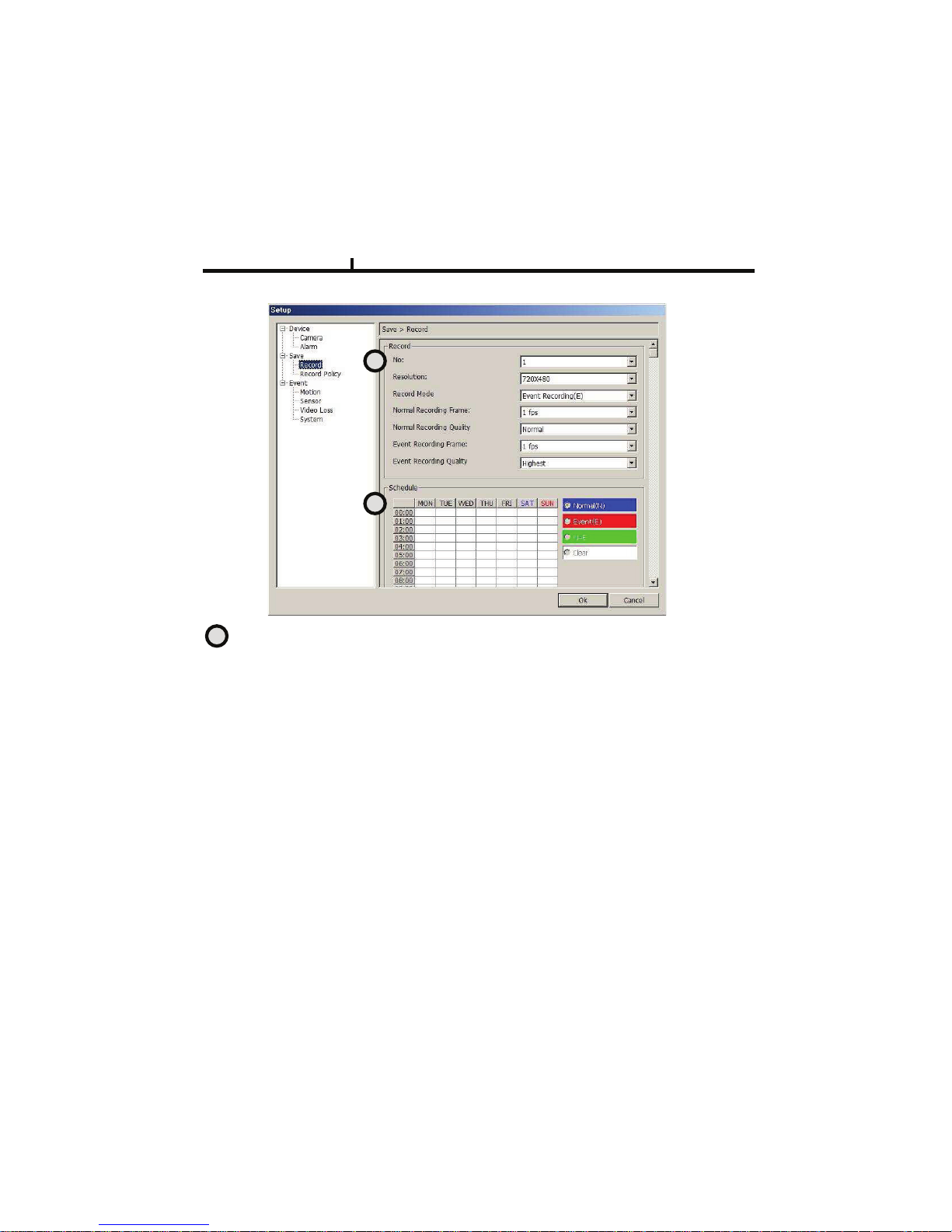
No : Item to select Camera No.
&.#@>=#EF#CAA#=G>#BC?>/C#>HECAAIJ#3G..@>#“@>A>B=#CAA”
.
Resolution : Item to change the resolution.
- NTSC : 720X480, 720X240, 360X240
- PAL : 720X576, 720X288, 360X288
Normal Record Frame :Item to select normal record frame.
Normal Record Quality : Item to select normal record quality.
Event Record Frame :Item to select Event (Motion + Sensor + Video Loss) record speed.
Event Record Quality : Item to select Event (Motion + Sensor + Video Loss) record quality.
Schedule : Item to select record schedule.
- Normal : Always Record
- Event : Motion, Sensor, Video Loss
- N + E : Always + Event Record
- Clear : Delete the current record schedule.
1
2
1
Chapter VI
68
Page 69
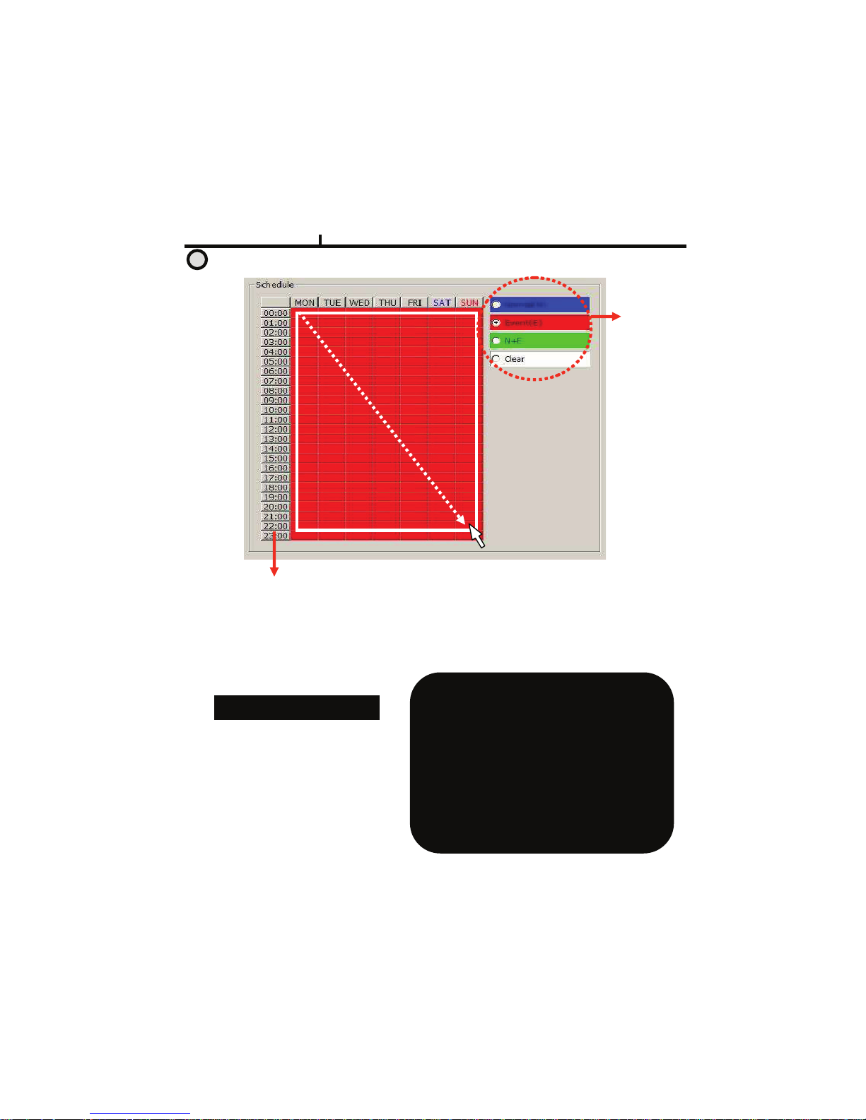
1. Select the
Record Mode
2.Select Day/Time
< Schedule of Record>
It is the list of selection in which schedule to
use in operating the relevant camera channel.
First select the item you need among
Normal time, Event and Normal time + Event.
Then drag mouse from the wanted position
on time line.
<<<< To edit schedule record,
you need to set record as schedule mode.
Schedule Indication by color
Normal(N) : (Blue)
Event(E) : (Red)
Normal(N) + Event(E) : (Green)
Clear (No Record) : (White)
2
Chapter VI
69
Remote Set Up <Record (Timetable)>
Page 70
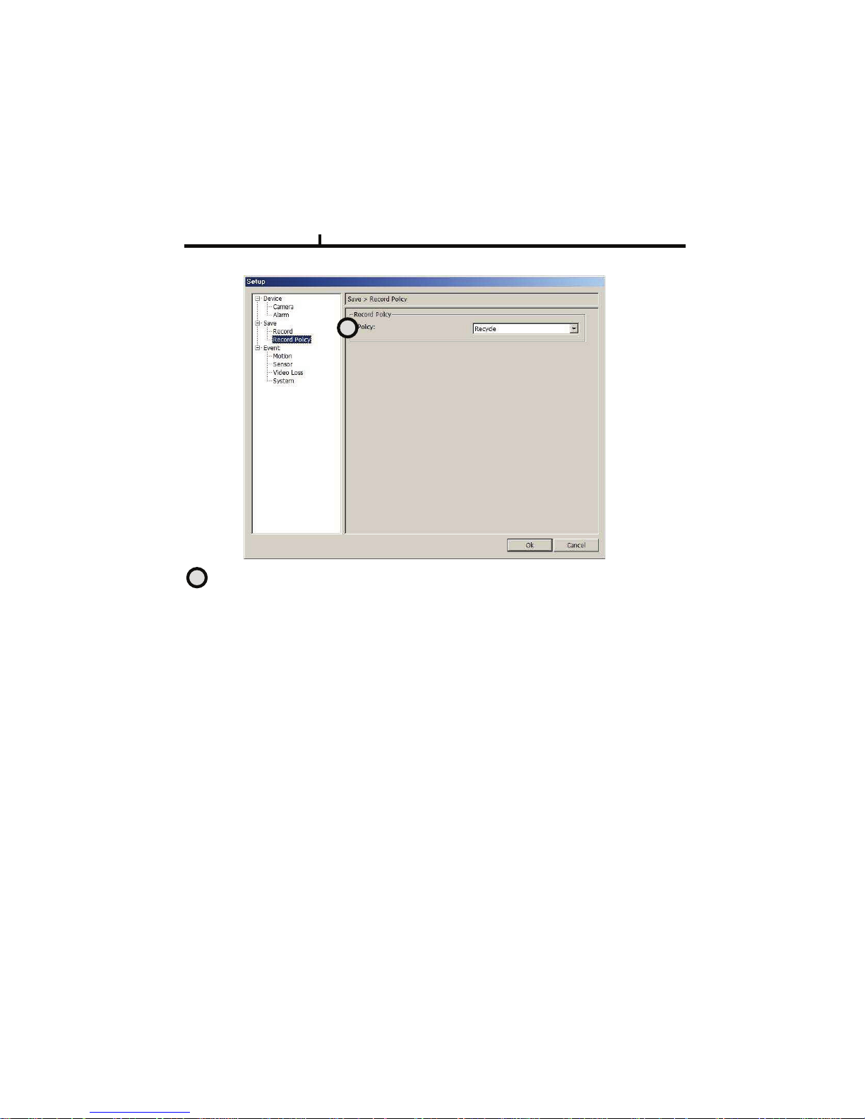
Record Policy: Item to select record policy
Remote Set Up <Record Policy>
Overwrite : When HDD capacity is almost consumed, It erases old data and record new.
Single Record : To stop recording on 100% of HDD capacity.
1
1
Chapter VI
70
Page 71
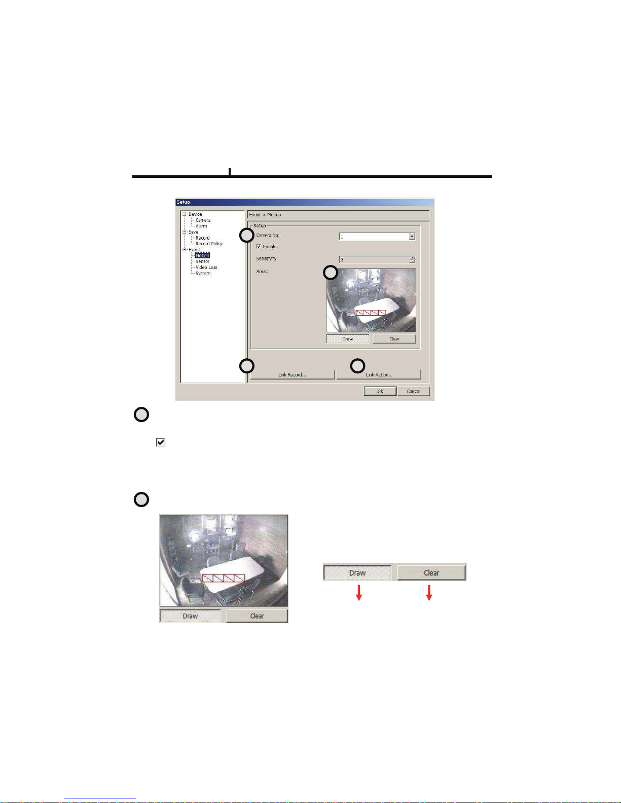
Camera No : Item to select Camera No.
&.#@>=#EF#CAA#=G>#BC?>/C#>HECAAIJ#3G..@>#“@>A>B=#CAA”
Enable : S>A>B=@#=.#E@>#?.=L.M#@>M@./J#:>?.KLMN#=G>#BG>BO#@=.F@#E@LMN#=GC= BGCMM>AD
Sensitivity : Adjusts the sensitivity in motion detection.
There are 5 steps and as the number increase, it gets more sensitive.
Area : Item to select motion area.
Area is selected when drag the mouse on the
image.
<Set Up Area Tool>
Area Draw
button
Area Clear
Button
Remote Set Up <Motion>
1
2
3 4
1
2
Chapter VI
71
Page 72
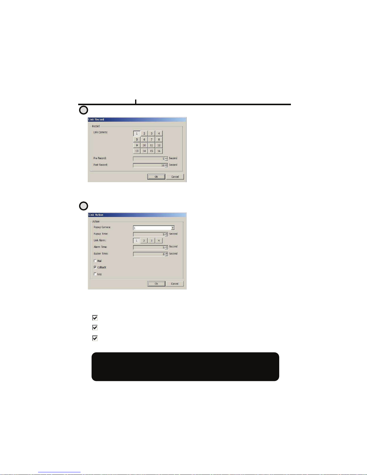
Remote Set Up <Motion (Link Record)>
Pre Record : Sets pre-event recording time. (Max 5 second)
Post Record : Sets post-event recording time. (Max 60 second)
Link Camera :
Selects which channel to record when
motion is detected on the relevant
channel.
<<<< Multiple selection possible
Remote Set Up <Motion (Link Action)>
Popup Camera :
Selects which channel to Popup when
motion is detected on the relevant
channel.
<<<< It works when the Popup setting is
‘Yes’ on DVR.
Popup Time :
Sets Popup time
Link Alarm :
Select Alarm to be linked when motion
Is detected.
<<<< Multiple selection possible
Alarm Time : Sets Alarm output time. (Max 30 second)
Buzzer Time : Sets buzzer output time in DVR. (Max 30 second)
Mail : When motion is detected, the log is sent to the selected e-mail.
Call Back : When motion is detected, the log is sent to the selected IP address.
Log : Item to save Log writing when motion detected.
(It is not recorded on the system Log but used for event search.)
Motion detection function is a mode to detect in accordance with the amount of color
Changes of image. So, please be careful that DVR keeps recording as continuous
motion when the image of camera is blinking caused by light problem or camera
Auto Iris problem.
3
4
Chapter VI
72
Page 73
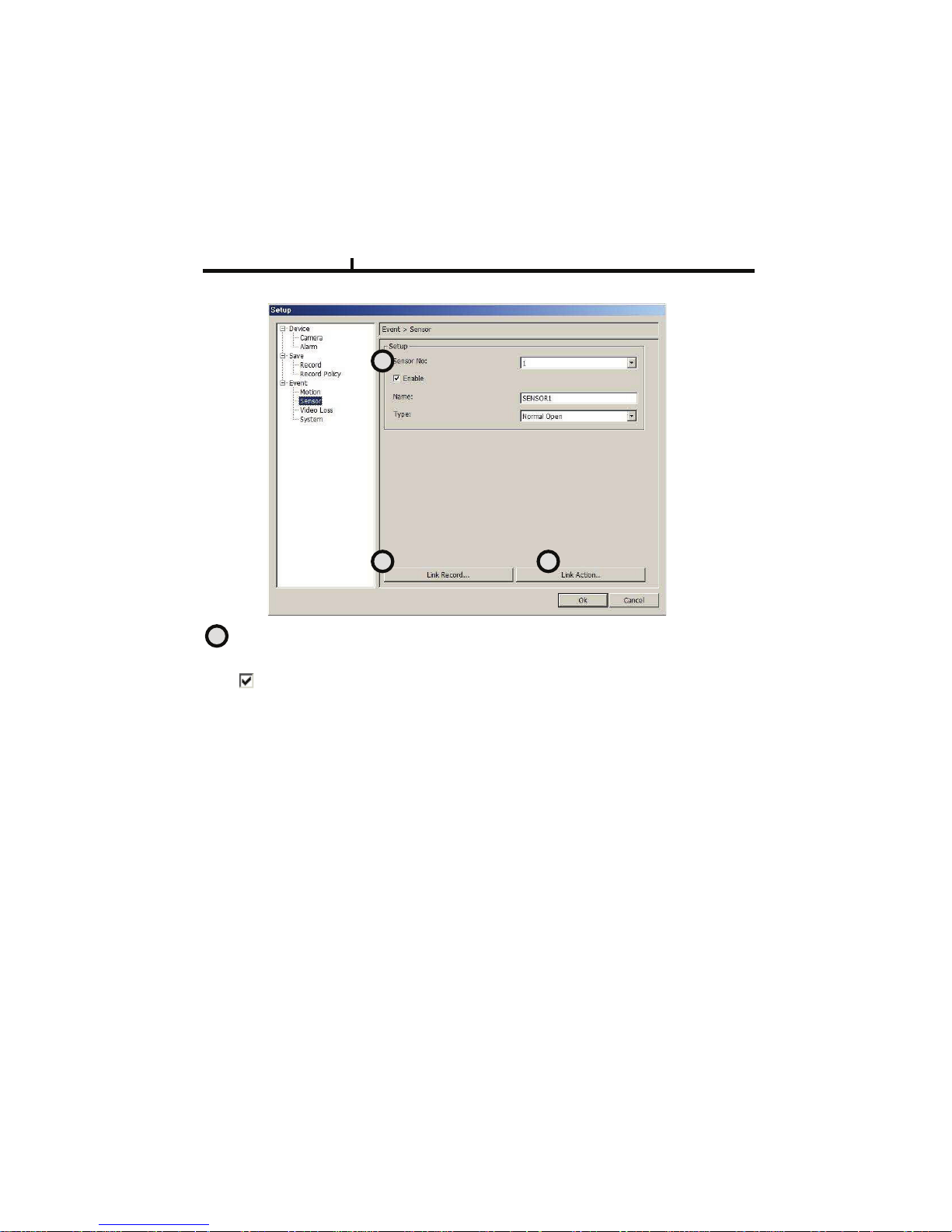
Remote Set Up <Sensor>
Sensor No : Sets sensor No.
To set up all the camera equally, Choose “select all”
.
Enable : Selects to use sensor, Removing the check stop using relevant sensor.
Title : Item to select sensor’s name.
Type : Item to select sensor type.
- Normal Open : Type of Alarm open in general situation.
- Normal Close : Type of Alarm close in general situation.
1
2 3
1
Chapter VI
73
Page 74
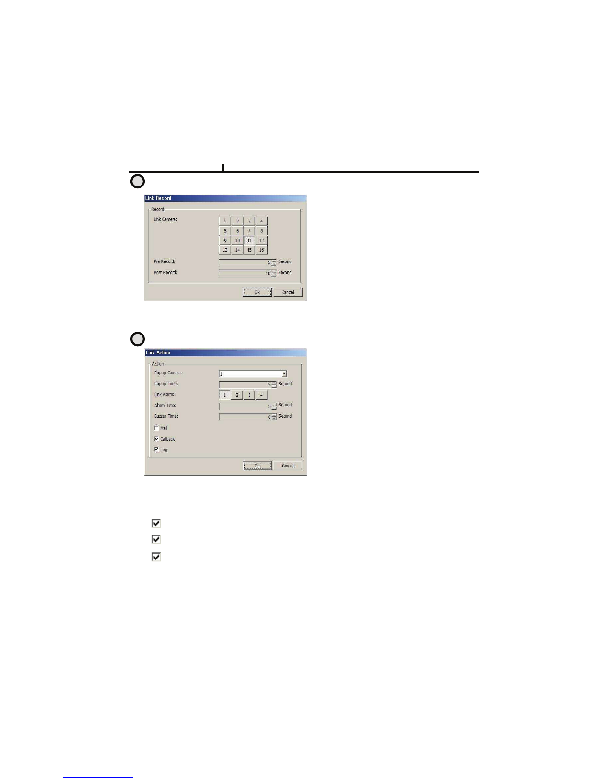
Remote Set Up <Sensor (Link Record)>
Remote Set Up <Sensor (Link Action)>
Link Camera :
%>A>B=@#QGLBG#BGCMM>A#=.#/>B./R#QG>M#
@>M@./#L@#R>=>B=>R#.M#=G>#/>A>KCM=#
BGCMM>AD
<<<< 7EA=LFA>#@>A>B=L.M#F.@@LSA>
7EA=LFA>#@>A>B=L.M#F.@@LSA>7EA=LFA>#@>A>B=L.M#F.@@LSA>
7EA=LFA>#@>A>B=L.M#F.@@LSA>
Pre Record : Sets up pre recording time. (Max 5 second)
Post Record : Sets up post recording time. (Max 60 second)
Popup Camera :
%>A>B=@#QGLBG#BGCMM>A#=.#T.FEF#QG>M#
@>M@./#L@#R>=>B=>R#.M#=G>#/>A>KCM=#
BGCMM>A.
<<<< 8=#Q./O@#QG>M#=G>#T.FEF#@>==LMN#L@#
8=#Q./O@#QG>M#=G>#T.FEF#@>==LMN#L@#8=#Q./O@#QG>M#=G>#T.FEF#@>==LMN#L@#
8=#Q./O@#QG>M#=G>#T.FEF#@>==LMN#L@#
‘U>@
U>@U>@
U>@’ .M#*5:
.M#*5:.M#*5:
.M#*5:.
Popup Time :
%>A>B=@#T.FEF#=L?>.
Link Alarm :
%>A>B=@#!AC/?#=.#S>#ALMO>R#QG>M#@>M@./#
L@#R>=>B=>RD#
<<<< 7EA=LFA>#@>A>B=L.M#F.@@LSA>
7EA=LFA>#@>A>B=L.M#F.@@LSA>7EA=LFA>#@>A>B=L.M#F.@@LSA>
7EA=LFA>#@>A>B=L.M#F.@@LSA>
Alarm Time : Selects Alarm output time. (Max 30 second)
Buzzer Time : Selects buzzer output time. (Max 30 second)
Mail : When sensor is detected, the log is sent to the selected e-mail.
Call Back : When sensor is detected, the log is sent to the selected IP address
Log : Item to save Log writing when sensor detected
(It is not recorded on the system Log but used for event search.)
2
3
Chapter VI
74
Page 75
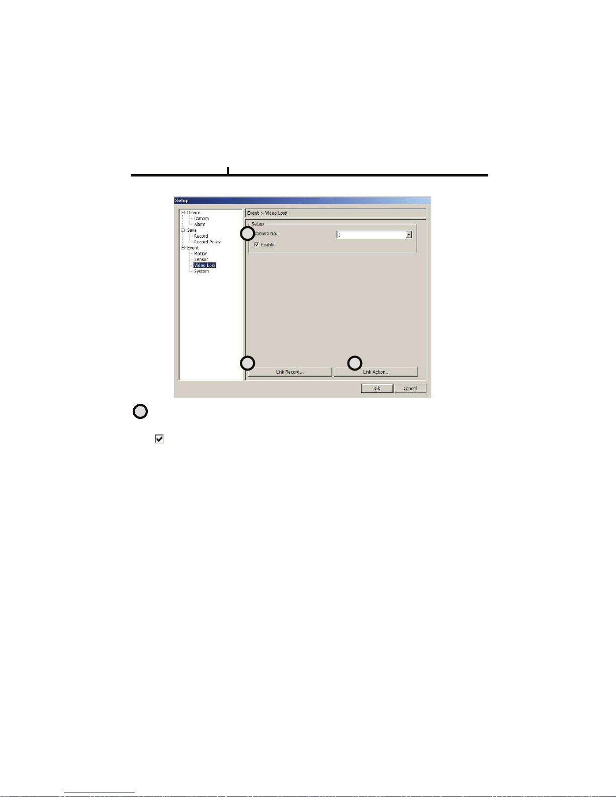
Remote Set Up <Video Loss>
Camera No : 8=>?#=.#@>A>B=#BC?>/C#".D
&.#@>=#EF#CAA#=G>#BC?>/C#>HECAAIJ#3G..@>#“@>A>B=#CAA”
Enable : Selects to use Video Loss.
1
2 3
1
Chapter VI
75
Page 76
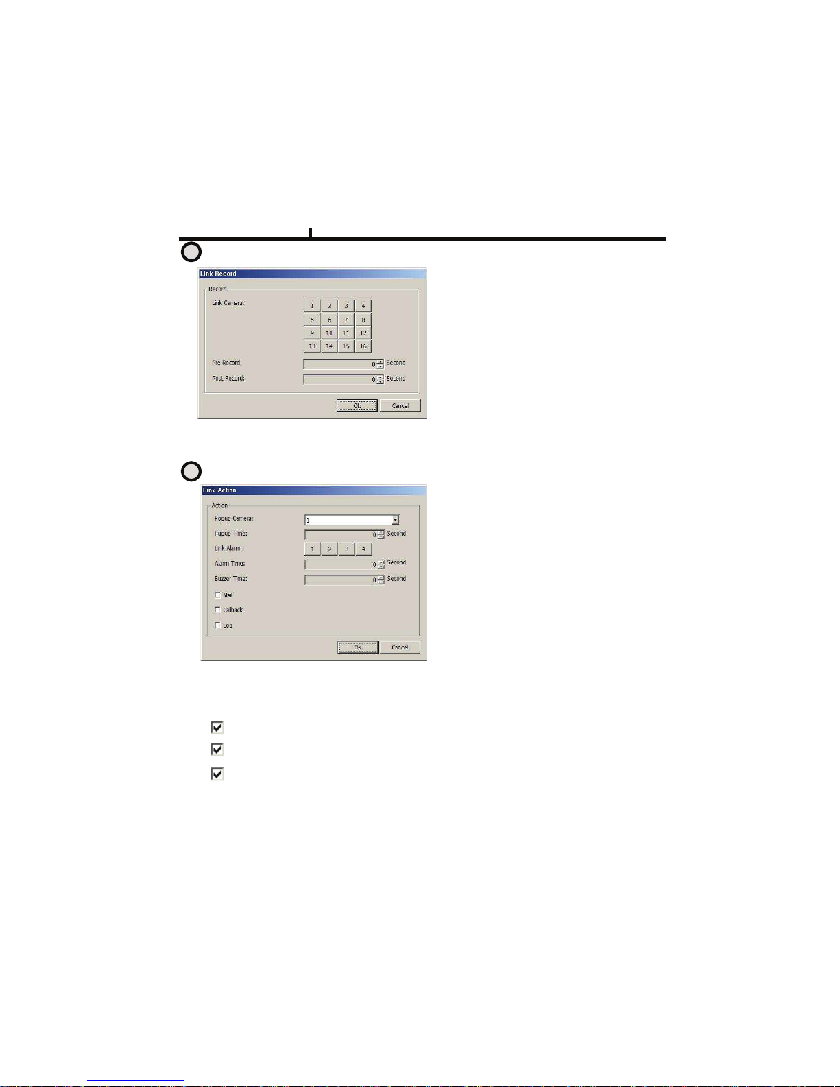
Remote Set Up <Video Loss( Link Record)>
Remote Set Up <Video Loss (Link Action)>
Link Camera :
Selects which channel to record when
video loss is detected on the relevant
channel.
<<<< Multiple selection possible
Pre Record : Sets up pre recording time. (Max 5 second)
Post Record : Sets up post recording time. (Max 60 second)
Popup Camera :
Selects which channel to Popup when
video loss is detected on the relevant
channel.
<<<< It works when the Popup setting is
‘Yes’ on DVR.
Popup Time :
Selects Popup time.
Link Alarm :
Selects Alarm to be linked when video
loss.
<<<< Multiple selection possible
Alarm Time : Selects Alarm output time (Max 30 second)
Buzzer Time :Selects buzzer output time (Max 60 second)
Mail : When video loss occurred, the log is sent to the selected e-mail
Call Back : When video loss occurred, the log is sent to the selected IP address.
Log : Item to save Log writing when video loss occurred.
(It is not recorded on the system Log but used for event search.)
2
3
Chapter VI
76
Page 77
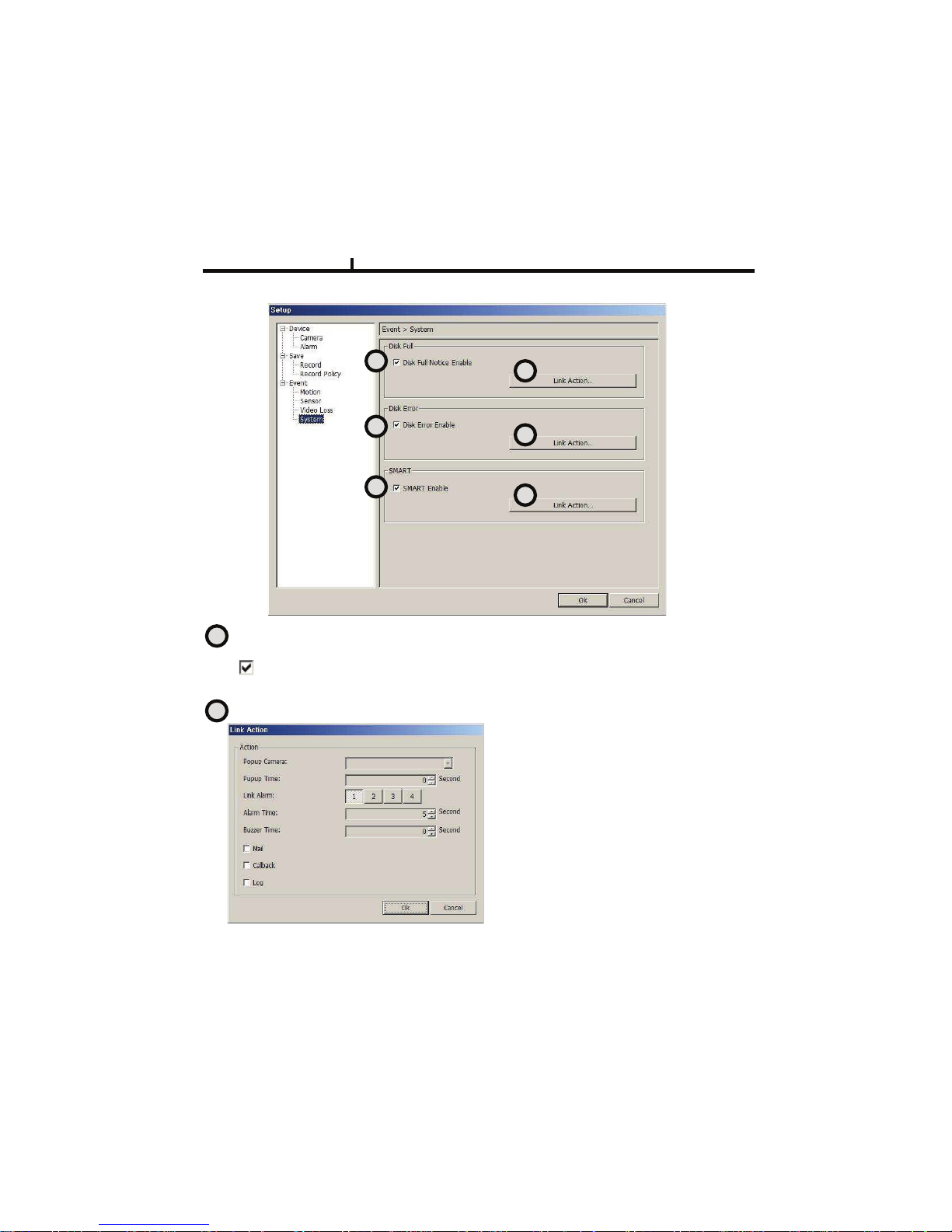
Remote Set Up <System>
DISK FULL : List for all installed HDD disks.
Disk Full Notice Enable : Activate Disk Full Notice when installed disks are full.
Remote Set Up <Disk Full (Link Action)>
Popup Camera :
Not available as of now
Popup Time :
Not available as of now
Link Alarm :
Selects which Alarm to be linked when all
installed HDD disks are full.
<<<< Multiple selection possible
Alarm Time : Selects Alarm output time. (Max 30 second)
Buzzer Time : Selects buzzer output time (Max 30 second)
1
3
5
2
4
6
1
2
Chapter VI
77
Page 78
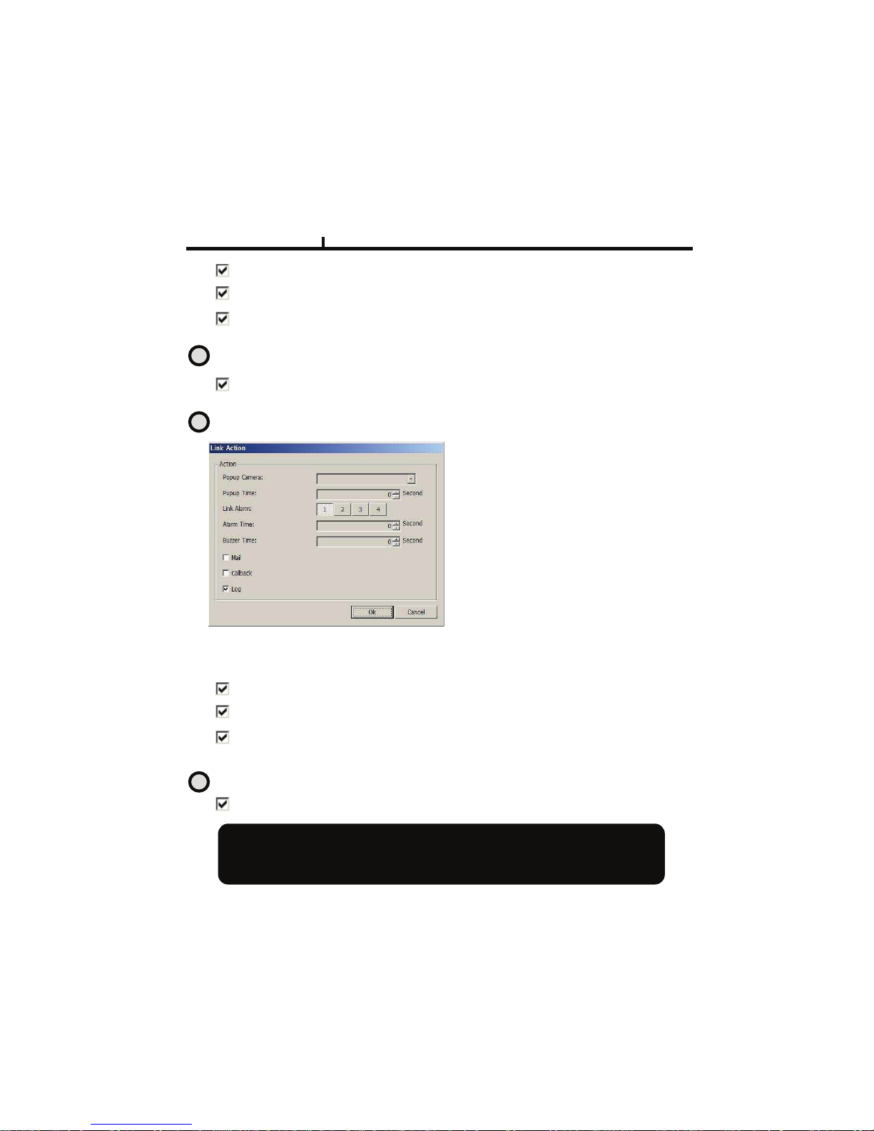
Mail : When all installed HDD disks are full, the log is sent to the selected e-mail
Call Back : When HDDs are full, the log is sent to the selected IP address.
Log : Selects to save Log writing when installed HDDs are full.
(It is not recorded on the system Log, but used for event search.)
Disk Error : Shows data error on all of the HDDs installed. (Additional function soon)
Enable Disk Error : When there is a disk error, it is linked to action.
Remote Set Up <Disk Error (Disk Action)>
Popup Camera :
Not available at this moment
Popup Time :
Not available at this moment
Link Alarm :
Selects Alarm to be linked when HDD
error.
<<<< Multiple selection possible
Alarm Time : Sets Alarm output time (Max 30 second)
Buzzer Time : Sets buzzer output time (Max 30 second)
Mail : When HDD error occurs, the log is sent to the selected e-mail
Call Back : When HDD error occurs, the log is sent to the selected IP address.
Log : Selects to save Log writing when HDD error.
(It is not recorded on the system Log but used for event search.)
SMART
Enable SMART : Select to use SMART feature.
SMART Function??
It checks the physical errors and observes the HDD disk continuously such as
Temperature, I/O device errors and general conditions of the HDD disk.
3
4
5
Chapter VI
78
Page 79
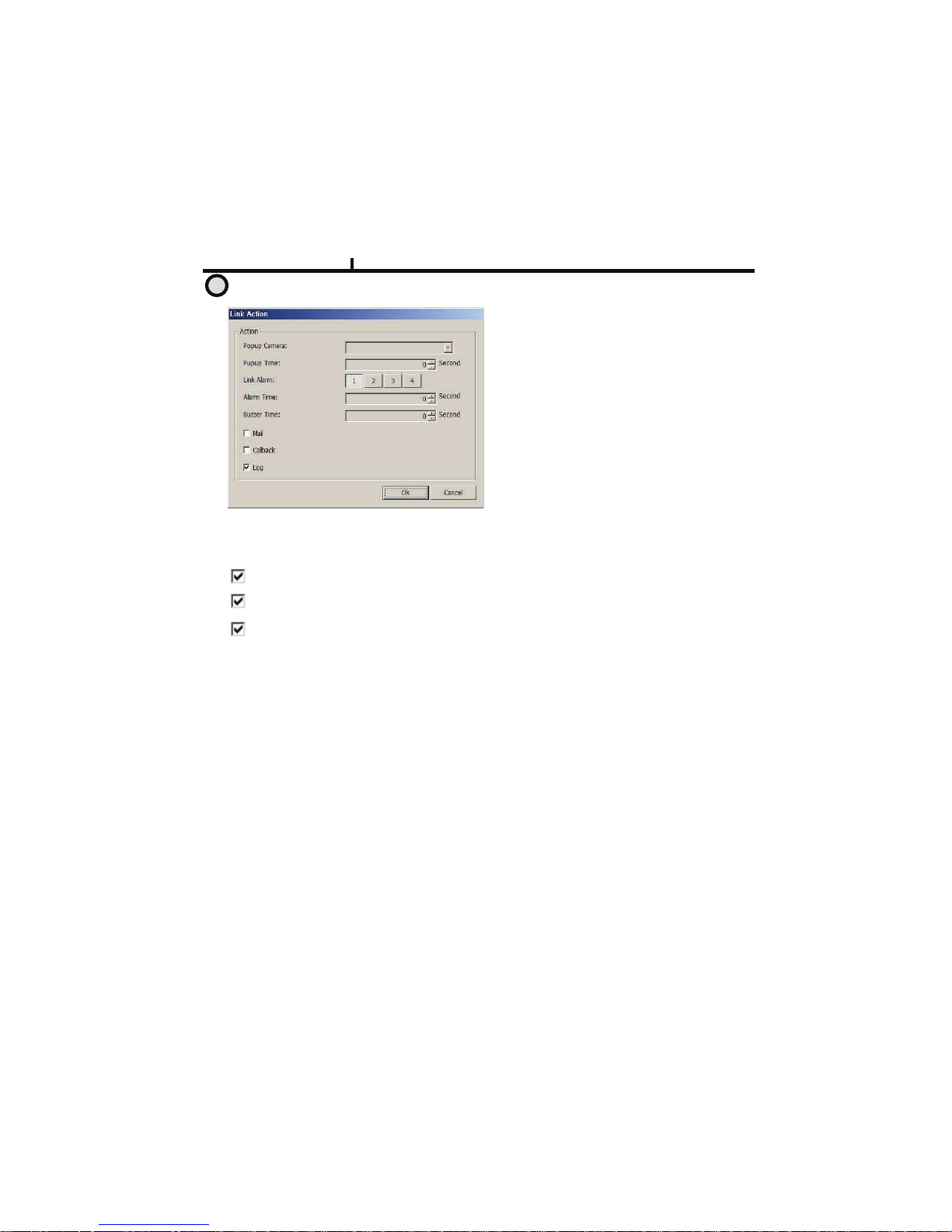
Remote Set Up <SMART (Link Action)>
Popup Camera :
Not available at this moment
Popup Time :
Not available at this moment
Link Alarm :
Selects which alarm to be linked
<<<< Multiple selection possible
!AC/?#&L?>###(#%>=@#!AC/?#.E=FE=#=L?>#27CV#-W#@>B.MR6
9EXX>/#&L?>#(#%>=@#9EXX>/#.E=FE=#=L?>#27CV#-W#@>B.MR6
Mail : When smart related problem occurs, the log is sent to the selected e-mail.
Call Back : When problem occurs, the log is sent to the selected IP address.
Log : Selects to save Log writing when smart related problem occurs
(It is not recorded on the system Log but used for event search.)
6
Chapter VI
79
Page 80
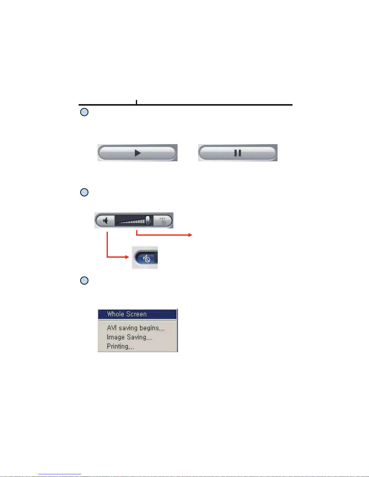
PLAY & PAUSE
Starts to play when pressed.
Starts or stops image transmission on the Remote Live screen.
This starts automatically when search or set in the setup menu.
Stops to play when pressed.
AUDIO Transmission
Controls Audio volume. Audio signal is sent on full screen mode only.
Mute Button :
Stops audio transmission.
Sound volume control gauge
Right Mouse Click Action
When the right button is clicked on Remote Live, the following menu below appears and the
following functions can be used.
Whole Screen : Hides the function
button and shows the image full
screen.
AVI Saving Begins :
Starts AVI saving of the channel
Selected.
Audio signal is saved on full
screen mode only.
Image Saving.. : Save image file of channel selected (Save JPEG or BMP)
Printing.. : Print current image of the channel.
Chapter VI
80
Page 81
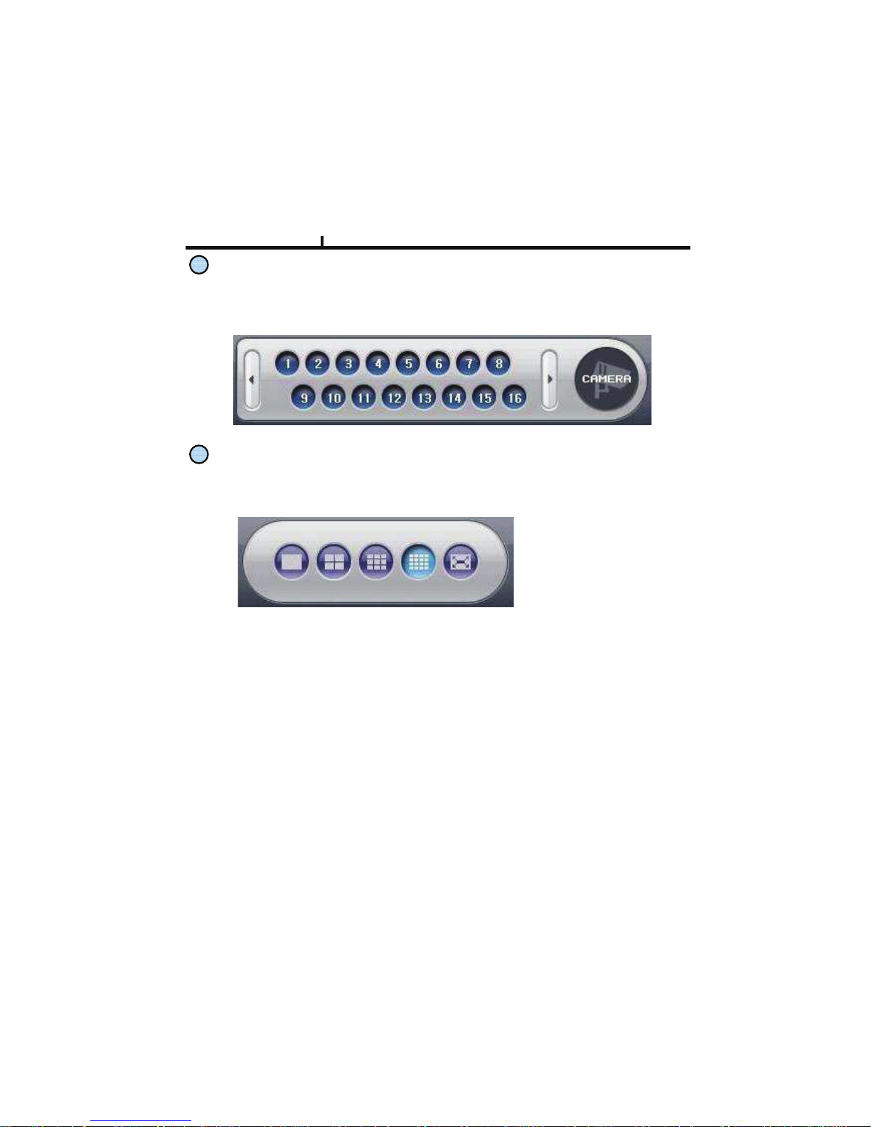
Channel Button
Moves to the channel selected and it has the same function as double click the left mouse
button on the selected channel.
Layout Modify Button
Screen Division Button : Selects desirable screen division.
Whole Screen : All buttons are hidden and the screen displays full.
Left double click of mouse returns to the previous screen from whole screen.
Chapter VI
81
Page 82
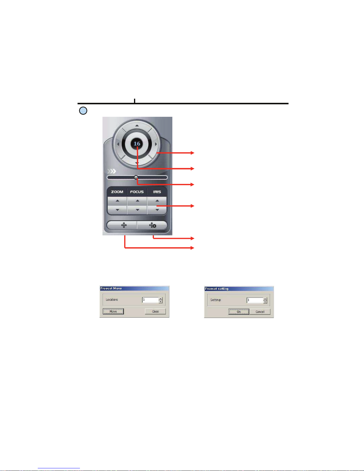
PTZ Operation
A camera supporting PTZ can be
used on Remote Viewer program.
Refer to PTZ support list
Direction Button :
Button to move top, bottom, left, right
Channel Indication :
Indicate current channel
Speed Control Button :
Button to control moving speed
Image Control Button :
Button to adjust Zoom, Focus, Iris
Pre set move button
Pre set save button
Preset Move: Move to saved preset No.
Preset Save : Save preset No.
<Preset Move> <Preset Save>
Chapter VI
82
Page 83
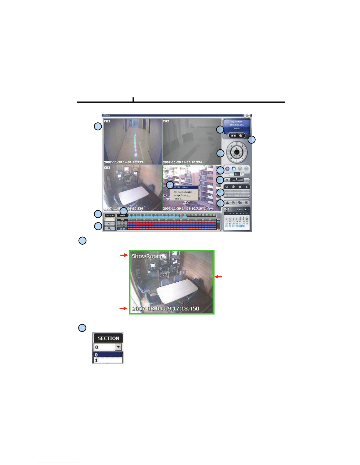
Camera Name
Recorded
Date/Time
Green Border Line :
Display the selected
camera.
Playback Display
SECTION
Selects section
Section is created when Date/Time is changed to former times.
Former Date/Time will be kept in section 0.
Newly set Date/Time will be kept in section 1……
Remote Search
Chapter VI
83
Page 84
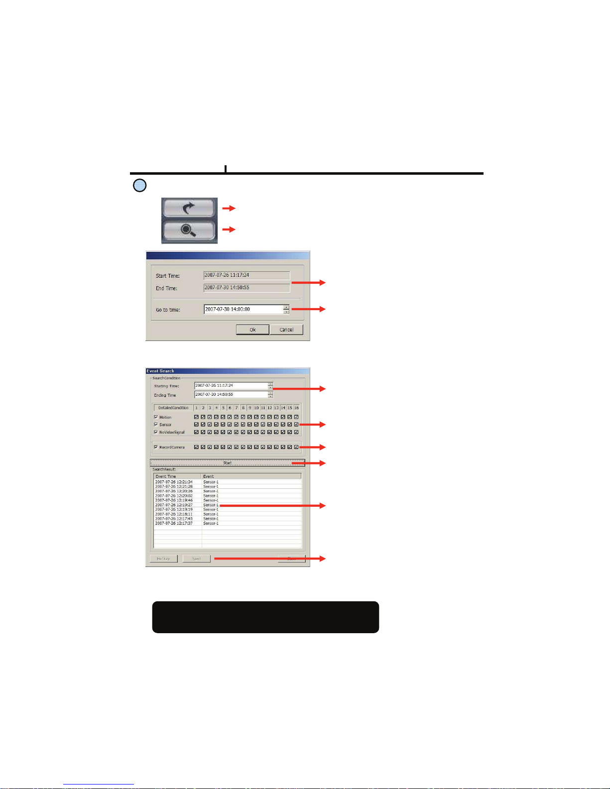
Move & Event Search
Move Button : Move to selected time
Event Search Button : Popup the event search window
<Move Window>
Shows start and end time of recorded
data.
Moves to the time to search and press
OK button.
<Event Search Window>
Select the time to event search
Select events in detail.
Select the camera to search.
Start event search. Click below Import
button to list events.
Shows current searched event lists.
Hotkey :Play the searched event.
Click Stop button first and select a
certain event list and click Hotkey to play
the event.
Import : Search the next event list.
10 lists are shown every time clicks
import buttton
Please make sure to select “WRITE LOG” of the system.
If not, event lists aren’t searched.
Chapter VI
84
Page 85
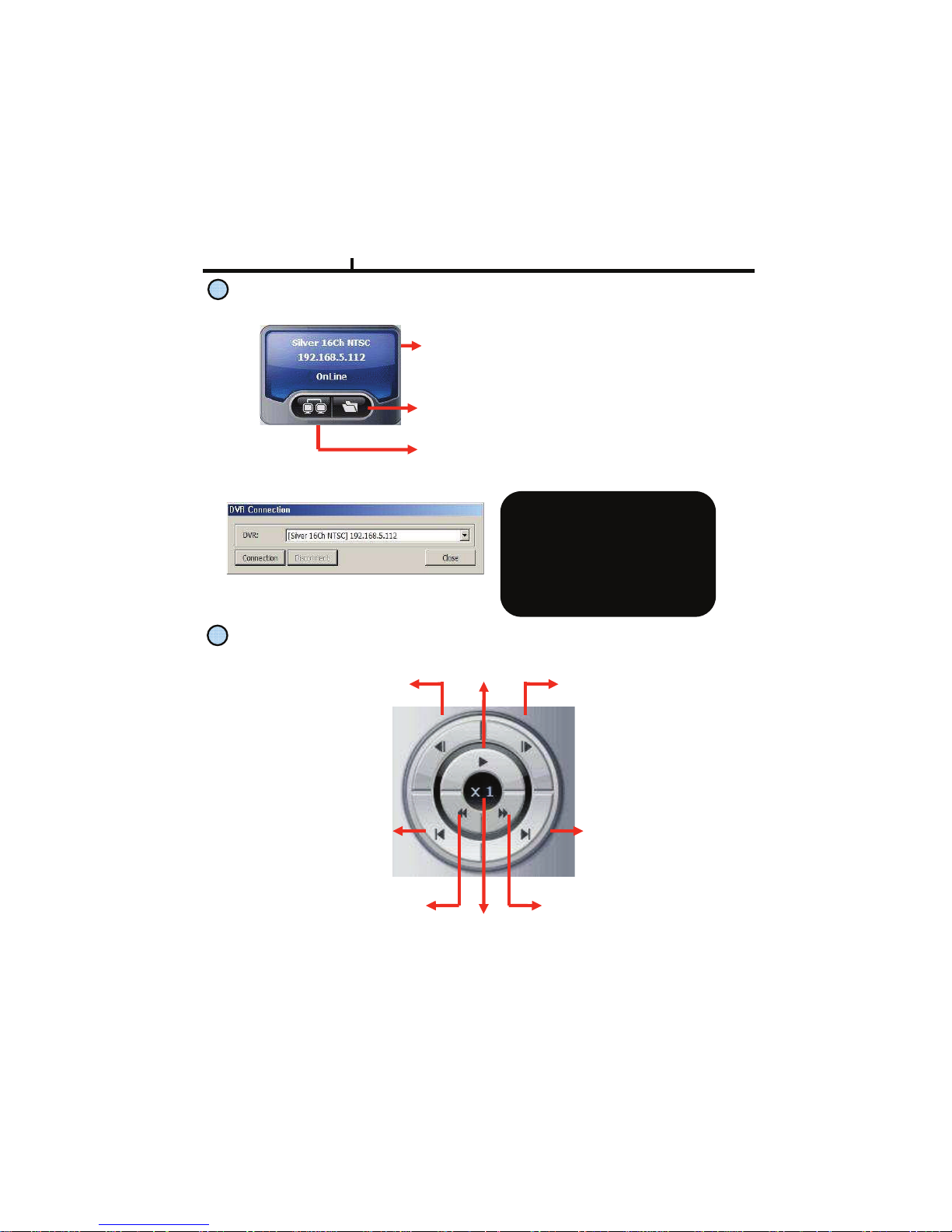
Connection Information and Button
!"#$%&'()’% *+,-.&/0&+112-%%&+*1&3#**-345#*&
%4+46%.
Connect/Disconnect Button :
Button to connect to other DVR in the saved list
<Connection List Window>
When many DVRs are registered
in the DVR list, each DVR can be
remotely searched without closing
The Remote Program.
The linked list s can’t be edited
while search.
Backup play button
Playback Button
Previous Frame :
Play previous frames
reverse direction
Next Frame :
Play next frames
forward direction
Play / Pause
Fast Rewind : Fast reverse
play every 1 minute
Fast Forward :
Fast play every 1 minute
End :
Move to end of record data
Starting :
Move to starting
of record data
Speed Control Bar
Chapter VI
85
Page 86
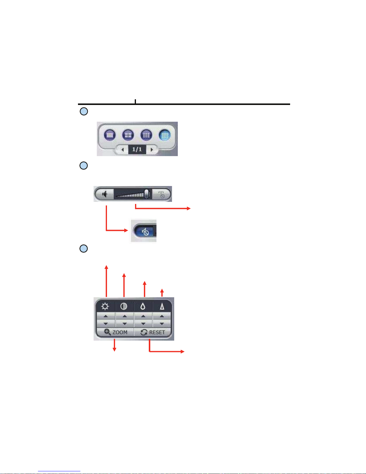
Screen Division Button
Screen Division Button
AUDIO Play
Controls audio volume. Audio signal is sent only on one full screen.
Mute Button :
Stops audio transmission
Sound volume control gauge
Image Control Button
Brightness adjustment button :
Adjusts the brightness of playing images.
Contrast adjustment button :
Adjust the contrast of playing images.
Sharpness adjustment button:
Adjust the sharpness of playing images.
Blurring adjustment button:
Adjusts the blurring of playing images.
Brightness
Contrast
Blurring
Sharpness
Reset button :
Initializes the adjusted image to original image.
Zoom Button :
Zoom the selected part
Chapter VI
86
Page 87
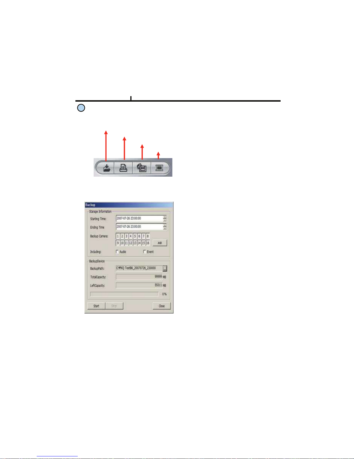
Saving Button
Backup
Print
Image Save
AVI Save
Back Up :
Backup the searched image as
compressed image file.
Print :
Print the searched images.
AVI Save :
Saves the searched images as AVI file.
Image Save :
Saves the searched images as Image File.
(Save JPEG or BMP)
Storage Information :
Select start and end time to backup
image.
Backup Camera :
Select the camera to backup
Including :
Selects audio and event to include.
Backup Path :
Selects the path to backup
Total Capacity :
Shows total capacity
Used Capacity :
Shows used capacity
Left Capacity :
Shows remaining capacity
<Backup Window>
Chapter VI
87
Page 88
88
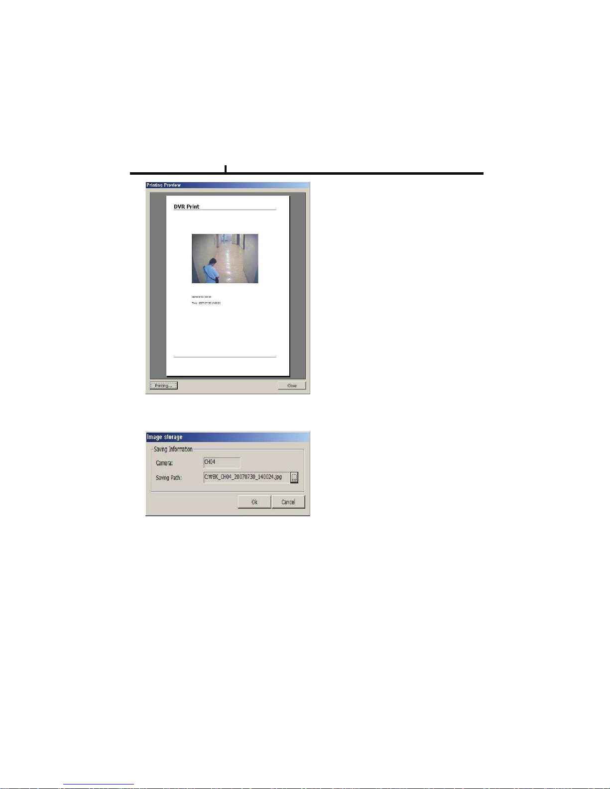
<Preview Window>
Preview :
Preview of the images to print,
which is printed with various information
written on the bottom of the image.
Image Format
JPG format :
Definition has a little loss due to loss
compression method, but archiving size
is small.
BMP format :
Archiving size is a bit big due to no
compression, but it can be saved as
higher definition than JPG.
<Image Save Window>
Saving Path :
Selects the path to backup.
Chapter VI
Page 89
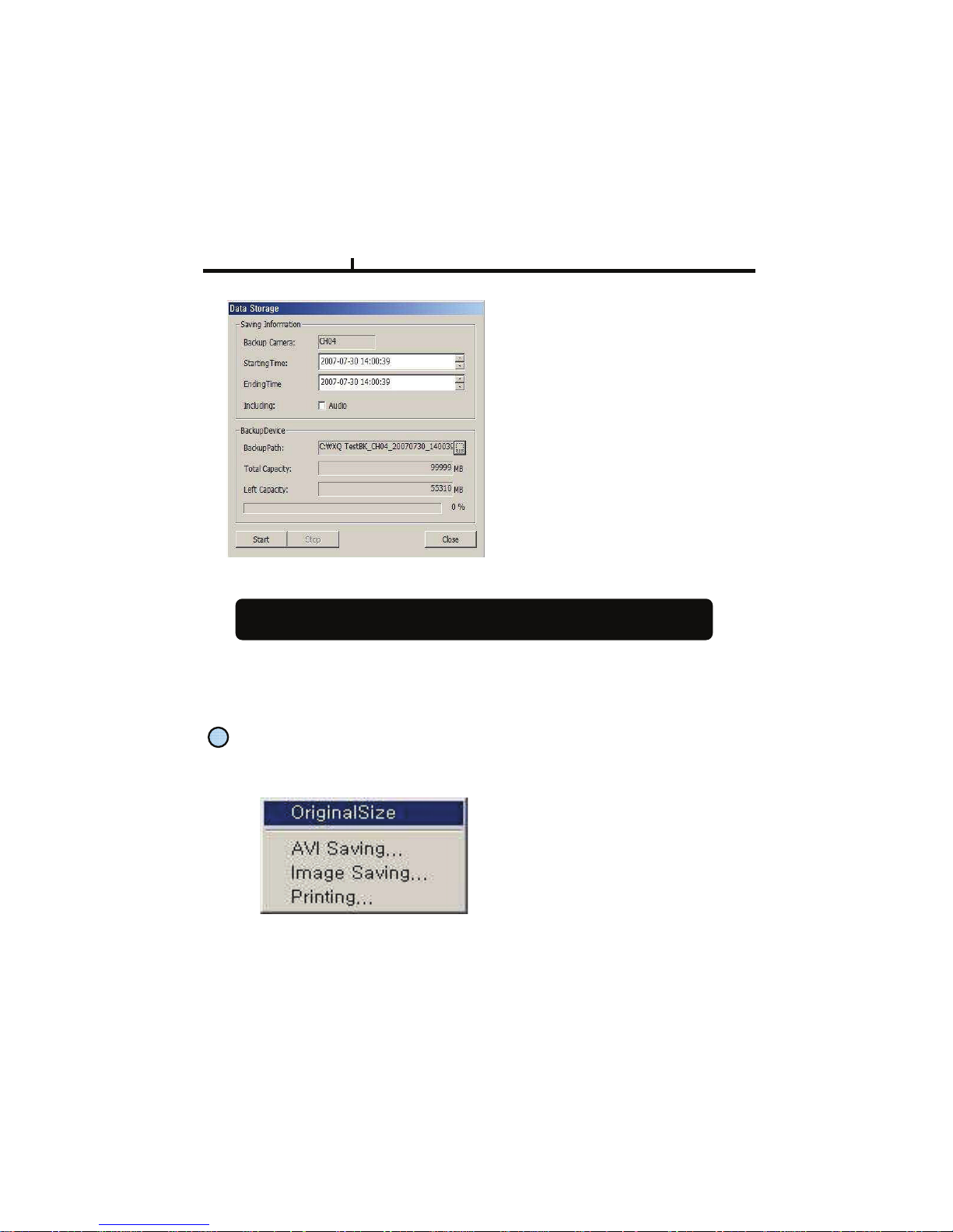
Storage Information
Selects camera No and start/end time to
save.
Including :
Selects audio to include.
Back Up Patch :
Selects the path to backup
Total Capacity :
Shows total capacity
Left Capacity :
Shows remaining capacity
Check “Caption option” of Media Player to display time/date of playing AVI file.
<AVI Save Window>
Right Mouse Click Action
When the right button is clicked, the following menu below appears and the following
functions can be used
Original Size : Shows original size.
AVI Saving :
Starts to save AVI file
Audio signal is save only on full
screen.
Image Saving.. : Save image of the selected camera (Save JPEG or BMP)
Printing.. : Print current image of the camera
Chapter VI
89
Page 90
11
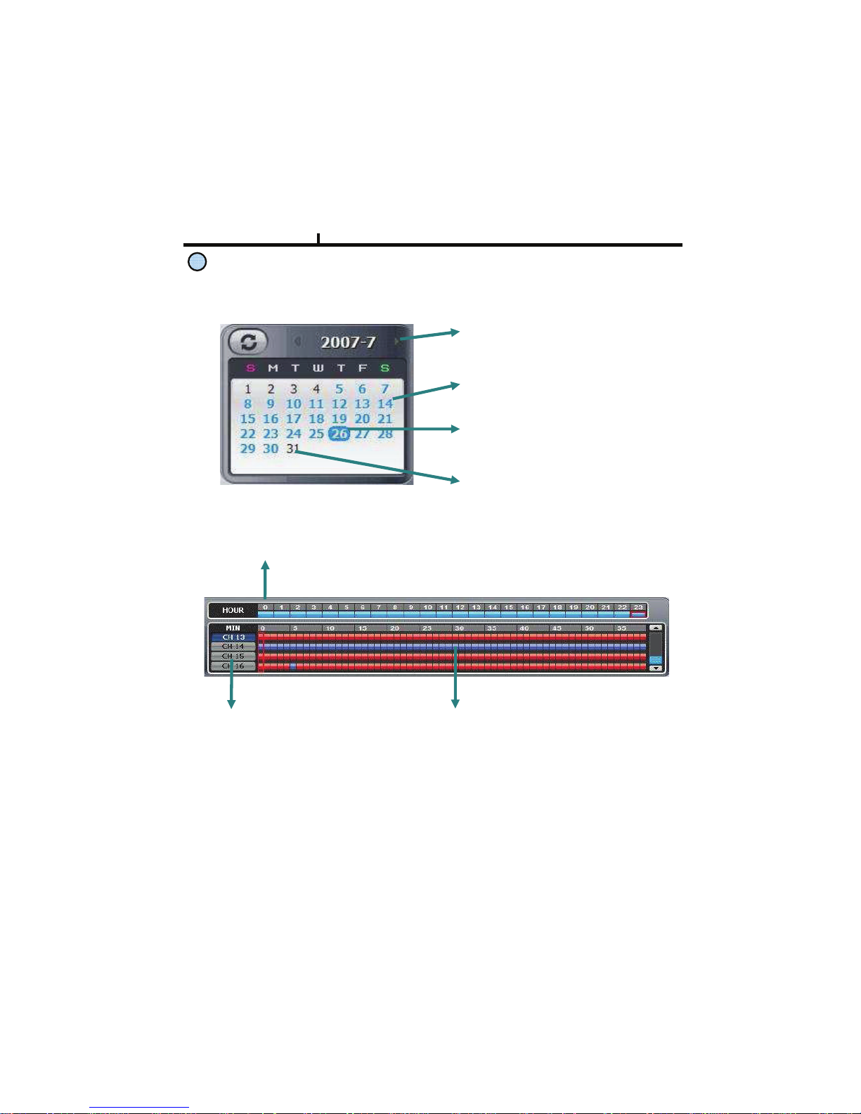
Time Table
Timeline Display : Displays in 24 hours system and one each line is 1 hour unit.
Camera Selection Button :
Select the camera.
Minute selection Pointer::
Select the minute.
Selects year/month/day and hour/minute to search the recorded data.
Year/Month Select Button :
Button to move previous and next month.
Recorded Date (Blue) :
Shows recorded date in blue.
Current Date (Blue Round) :
Shows current date in blue round.
No Recorded Date (Black) :
Shows no recorded data in black.
Chapter VI
90
Page 91
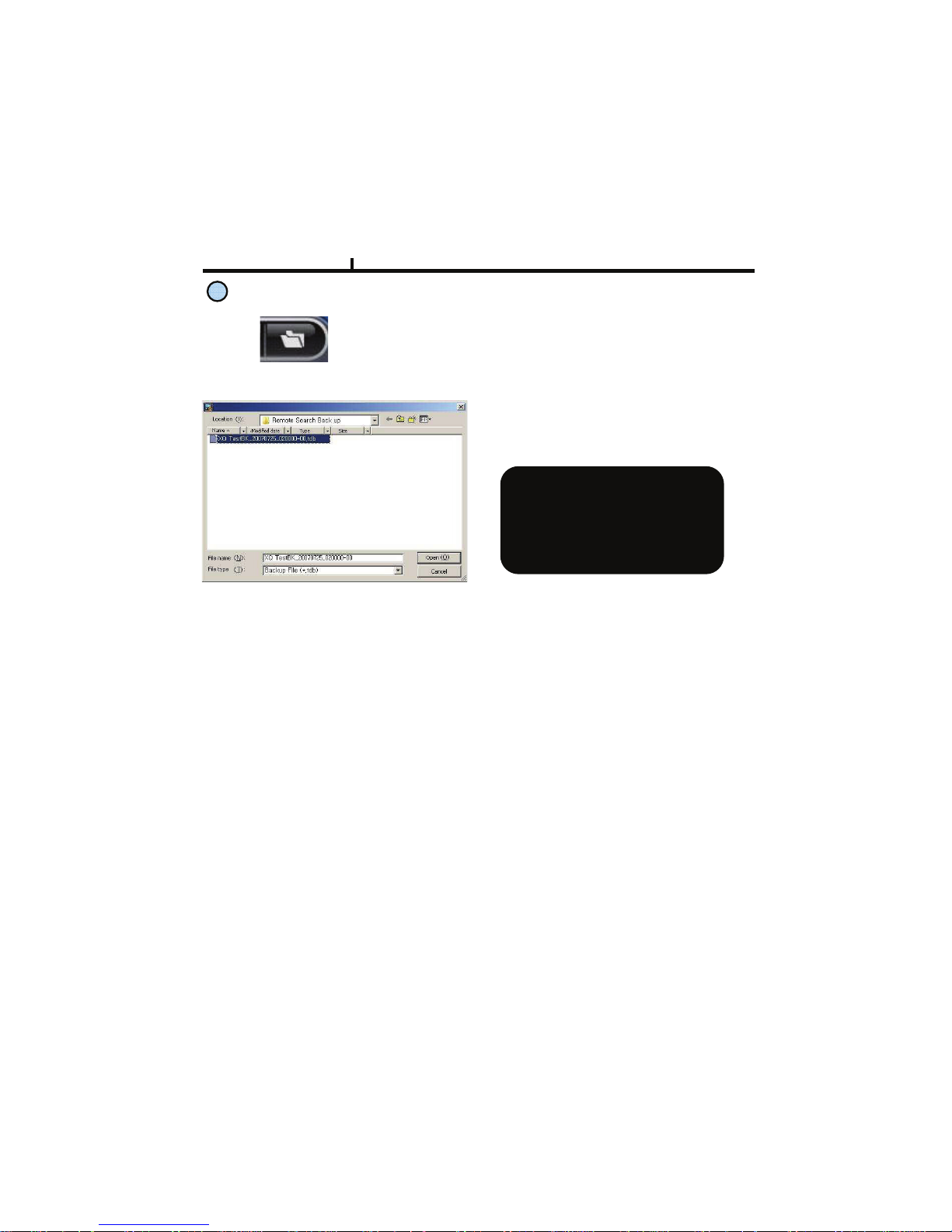
Backup Playback Button :
Click to backup playback
Select the backup data to play.
Backup playback can play a data
of Image file.
Windows Media Player can play a
data of AVI image files .
12
Chapter VI
91
Backup Playback
Page 92
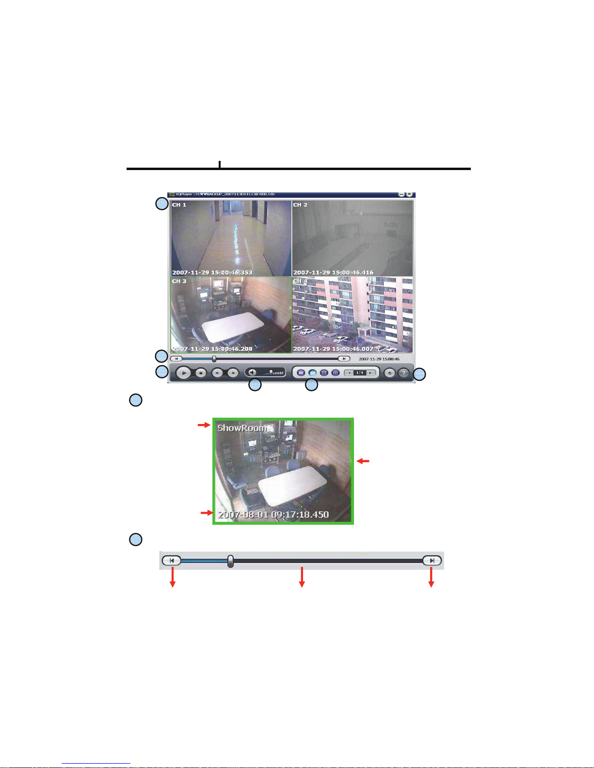
92
1
Camera Name
Recorded
Time/Date
Green border line :
Display the selected
camera.
Search screen
2
Starting/End
Move to end of record data
Move to starting record data
Play Progress Bar
PLAYER
Chapter VI
1
2
3
4 5
6
Page 93
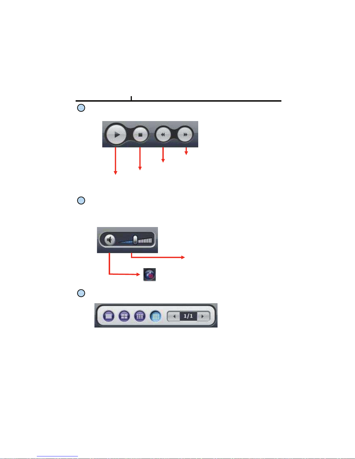
3
Play button
Play / Pause
Stop
Fast Forward
Fast Rewind
4
Sound volume Control Button
Mute Button :
Stops audio transmission
Sound volume control gauge
Audio signal is sent only on one full screen.
5
Layout Button
Layout button : Button to select screen division mode .
Chapter VI
93
Page 94
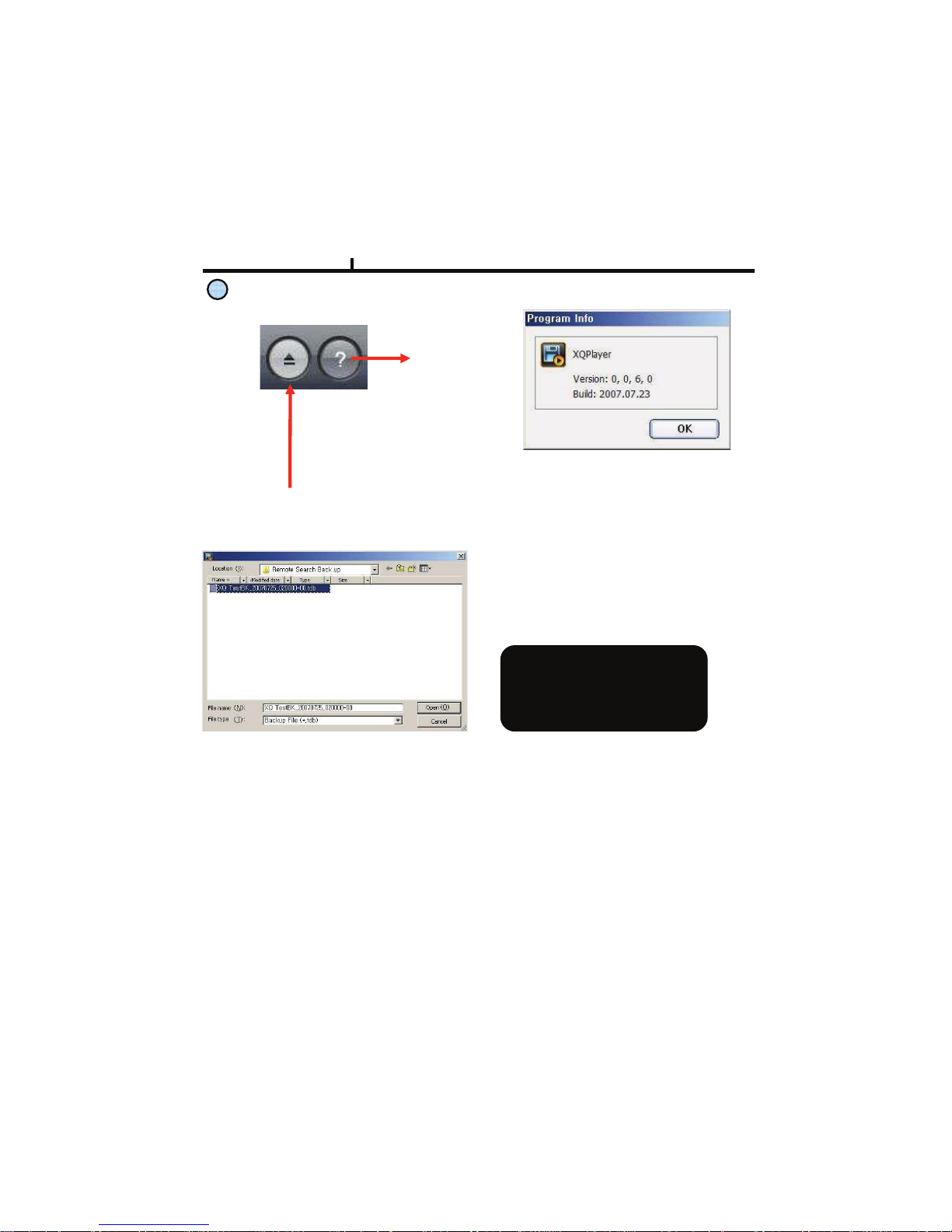
6
Call function/Program Info
Call Function Button :
Button to call in the back up file.
Information :
Shows program
information.
<Program Info Window>
Select the backup data to play
Backup playback can play a data
of Image file.
Windows Media Player can play
a data of AVI image files .
Chapter VI
94
Page 95

95
Chapter-VII. APPENDIX
Page 96
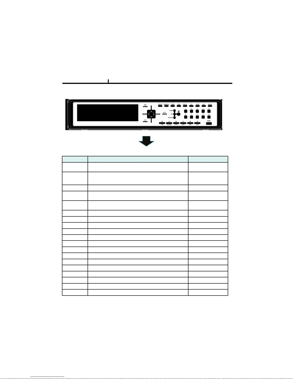
ITEM DETAIL REMARK
ESC
- Exit menu/mode
- Return to search mode during playback
ENTER
- Select each menu
- Confirm input setup value
- The Same function as mouse left click
SETUP
- Enter into Setup menu
BACKUP
- Backup menu in search mode
- Prompt backup in playback mode
MENU
- Menu setup
- The same as mouse right click
PTZ
- Enter into PTZ control mode
ALARM
- Enter into Alarm control mode
SPOT
- Spot monitor control
RECORD
- Panic Record On/Off
DISPLAY
- Display screen division mode
SEQUENCE
- Start/end sequence display mode
FREEZE
- Pause screen display
ZOOM
- Zoom In/Out screen display
BACK STEP
- Reverse step playback CALENDAR SEARCH
PLAY/PAUSE
- Play/pause LATEST SEARCH
STEP
- Step playback EVENT SEARCH
REW
- Rewind FIRST SEARCH
FF
- Fast forward LAST SEARCH
0 ~ 9
- 0 ~ 9
Chapter VII
Front Key Explain
96
Page 97
97
ITEM DETAIL REMARK
BACK STEP - Enter to calender search mode - Enter from search mode
PALY/PAUSE - Move to ending playback - Enter from search mode
STEP - Enter to event search mode - Enter from search mode
REW
- Starting to Playback data - Enter from search mode
FF - End to Playback data - Enter from search mode
Chapter VII
Hot Key to control the playback and display output on search display
Page 98
Product Warranty
98
02#1634&
7+,-
!-25+9&7:;
'-+9-2 >112-%% >112-%%
?6%4#,-2&
*+,-
Warranty period – 2 year
As warranty period is counted from the date of purchase, it is recommended that you
get the date of purchase to be written.
(If you are not sure about the date of purchase, the warranty period is counted from
the date when six months are passed from the date of manufacture.)
Free Service
We will recompense in accordance with free service or Consumer Damage
Compensation, Ministry of Finance and Economy’s Notification, in case there is any
failure of performance or function, which occurred naturally under normal use of
product within one year (warranty period) after purchasing the product.
.
Pay service
1. In case of failure due to consumer’s mistake
-in failure due to the careless handling, repair or conversion of the consumer
-in failure due to the repair by unqualified person instead of dealer or service
center engineer
-in failure or damage due to falling or such things during relocating after
installing
-in failure due to abnormality of used power or inferiority of the networks and
apparatus that is attached to this product
>112-%% >112-%%
8#1-9
'+4-&#<&
=623"+%-
2. In case of other reasons such as disasters (fire, salt damage, flood, landslip, etc.…)
 Loading...