

opticis Stretch DVI M1-201SA-TR User Manual

User’s Manual
(For M1-201SA-TR)
Doc No. : OE-D150316-201SA / Rev2.9
Stretch DVI
TM
Manual Contents
__________________________________________
Manual Contents 1-0
Welcome! Product Description 1-1
System Requirements for Setup 1-2
Installation 1-3
Troubleshooting, Maintenance, Technical Support 1-5
Product Specifications 1-6
Warranty Information 1-8
Warning 1-9
Regulatory Statements 1-10
Pictorials
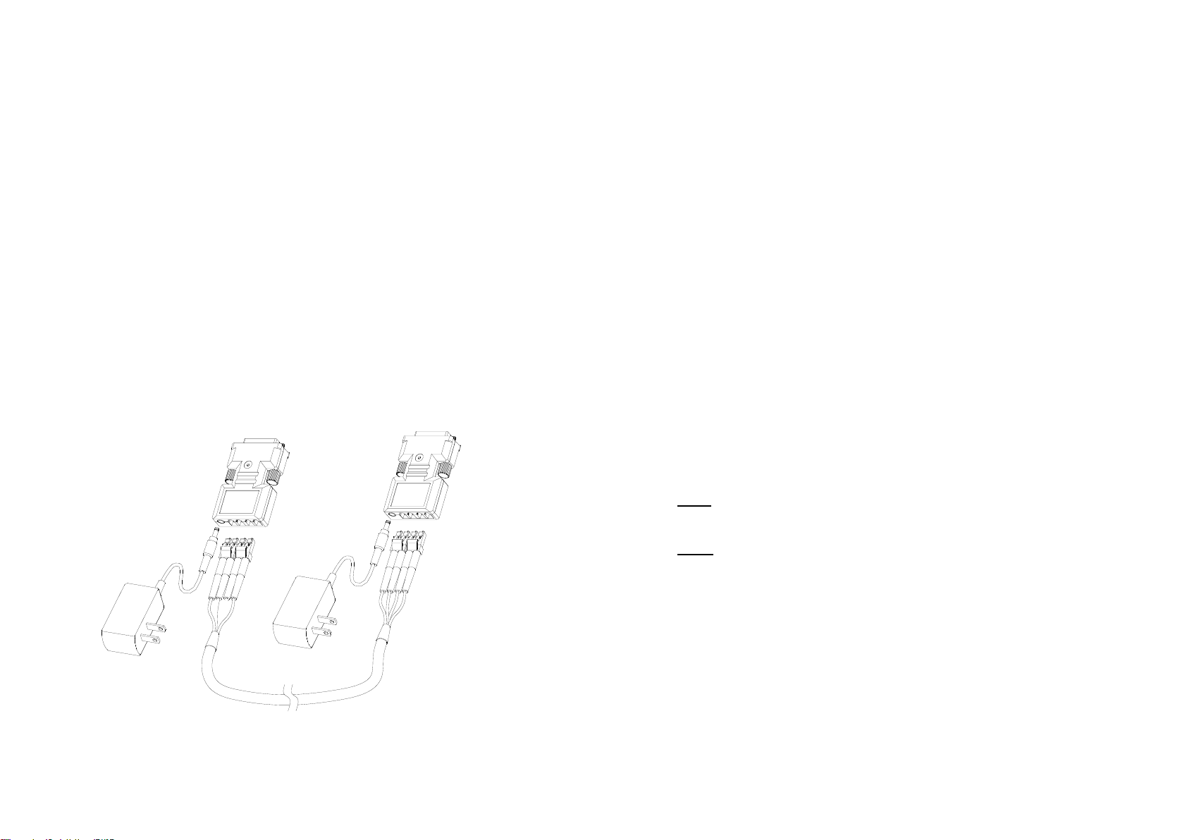
Figure 1 – Optical DVI Extension Module System 1-1
Figure 2 – Auto EDID button 1-3
Figure 3 – Connection of optical fiber 1-4
1-0 Manual Contents
Welcome!
Congratulations on your purchase of the Stretch DVITM M1-201SA-TR Optical
DVI (Digital Visual Interface) Extension Module. This manual contains
information that will assist you in installing and operating the product.
Product Description
The M1-201SA-TR optical DVI module transmits four (4) optical data, Red,
Green, Blue and clock and can be extended up to 500 meters (1,640ft) over a
pair of LC duplex multi-mode fibers or four (4) LC simplex multi-mode fibers at
WUXGA (1920x1200) at 60Hz vertical refresh.
The EDID (Extended Display Identification Data) in a display can be read and
restored by just plugging once transmitter to the display. This Auto EDID
programming feature makes the installation of M1-201SA more easy and
flexile at any variable resolution display systems.
For your convenience, UXGA EDID would have been done before shipment
as a default.
Shipping Group
M1-201SA-TR Optical DVI Extension Module: One (1) pair
DC power adapter: Two (2) units
User’s Manual
Figure 1 – Optical DVI Extension Modules System
1-1 Welcome, Product Description
System Requirements for Setup
Hardware requirements
You have to have a DVI graphic controller or card having a DVI
port in your PC, SUN or Mac systems. It should support the
maximum graphic resolution feature of displays to be connected.
No special requirements for memory size, CPU speed and
chipsets, if you’ve already properly installed your DVI graphic
controllers or cards.
Software requirements
No special restrictions, if you’ve already properly installed your
DVI graphic controller in your OS.
AC/DC Power Adapter Technical Advisory
The transmitter (Tx) module of M1-201SA-TR is designed a power
protection circuit from conflict of power supply between the external
DC power adapter and your graphic card through the DVI pin.
However, the receiver (Rx) module should be supplied by an AC/DC
power adapter.
Tips: In general, most of laptops or desktop PCs with PCI Express graphic
card require using an AC/DC power adapter for the transmitter module.
Note: Recommend to use power supplying adapters offered by Opticis,
which has short-circuit break features.
1-2 System Requirements for Setup
Step 4
Connect another 5V power adapter to the receiver. Then blue LED ON.
Step 5
Plug the receiver to the DVI receptacle of display.
Note: Be recommended NOT to use any intermediate cable or adapter between
them to avoid undesirable performance degradation.
Step 6
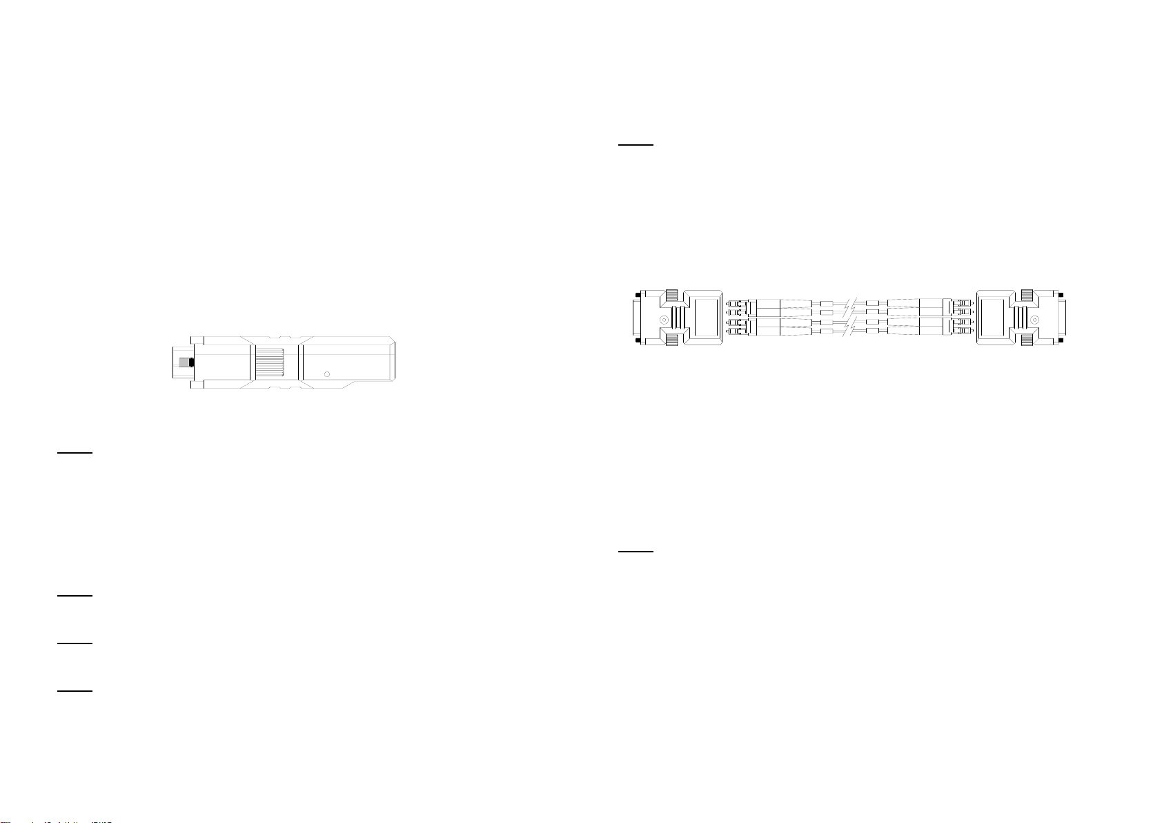
Connect each LC multi-mode fiber one by one as shown in figure 3.
Figure 3 – Connection of optical fiber
Step 7
Makes the PC Power On.
Step 8
Go to Display Properties in Windows systems and click the tap of Settings. Then
you can set the right display resolution to meet your display. Once you set the
right resolution, you could see displaying the initial screen at the same resolution
as just before you powered on.
Note: If you cannot see the initial screen of the OS system and have skipped the
Step 1 and Step 2, you have to follow the Step 1 and Step 2 instructions.
Step 9
You can see processing to adjust the system screen.
1-4 Installation (continued)
1
2
3
4
12
3
4
Transmitter
Receiver
Installation
Important: Please use the installation procedure below. Improper or no
operation may result if the start-up sequence is not correctly followed.
Step 1
Plug the 5V power adapter to the power jack of the transmitter, and connect
the adapter to the mains electricity. Ensures the blue LED ON.
Step 2
For Auto EDID programming;
a) Push the Auto EDID button with a narrow pin. After three times
blinking of Blue LED, it will be turned off.
b) Connect the powered transmitter to display while turned on, not
to the PC. The LED blinking indicates reading the EDID. LED ON
after blinking notices programming done.
c) Disconnect the transmitter from the display.
Figure 2 – Auto EDID button
Note: If you want to change the display, please do again the step 2. The
default EDID in factory ship-out is programmed in the VESA standard of
UXGA 60Hz.
Step 3
Plug directly the transmitter module to DVI receptacle of PC and confirm if the
blue LED ON. Or, connect 5V power adapter to the power jack of the
transmitter.
Note: Be recommend NOT to use any intermediate cable or adapter between
them to avoid undesirable performance degradation.
Note: If you use laptop or Desktop PC with PCI Express graphic card, we
recommend using 5V power adapter for the transmitter.
Note: Please DO NOT look directly into the LC receptacles of the Transmitter,
while it is powered on, although this product is regulated strictly enough to
operate under the LASER Class I, classified by CDRH/FDA for eye safety.
1-3 Installation
 Loading...