

Page 1
WWW.OPTICIS.COM
19” 1RU Frame and Optical Passive Splitter
User’s Manual
(OPSR-2, OPS-xyz)
Doc No. : OS-D150102 / Rev1.1
- 1 -
Page 2
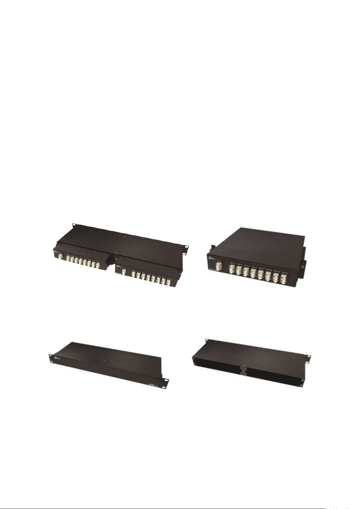
Fig. 1: OPSR-2 with two (2) OPS-216L (Rear)
Fig. 2: OPS-216L
Fig. 3: OPSR-2 (Front)
Fig. 4: OPSR-2 (Rear)
Welcome!
Congratulations on your purchase of the 19” 1RU frame, OPSR-2 and optical passive splitter,
OPS-xyz. This manual contains information that will assist you in installing and operating the product.
Product Description
1. OPSR-2 and OPS-xyz
OPTICIS OPSR-2, 19” 1RU frame is an ideal solution for modular and systematic fiber-optic needs.
Opticis new optical passive splitter, OPS-xyz distributes optical signal over single-mode fiber up to 16
channels without any active device or electrical power to maximize the efficiency and minimize the
cost of digital signage installation. Two (2) units of OPS-xyz can be fitted into 19” 1RU frame, OPSR-
2 and for sure one unit can used as stand-alone type to save the installation space.
[Note] * Applicable Products with OPS-xyz are DVFX-110, M1-201DA-TR, M1-203D-TR and M1-
3R2VI-DU.
- 2 -
Page 3
** OPS-xyz is designed for single mode fiber distribution. Do not connect it by multi-
Items
Descriptions
OPS-104S
1x4 SC optical passive splitter
OPS-108S
1x8 SC optical passive splitter
OPS-116S
1x16 SC optical passive splitter
OPS-408S
4x8 (4ea of 1x2) SC optical passive splitter
OPS-208L
2x8 (2ea of 1x4) LC optical passive splitter
OPS-216L
2x16 (2ea of 1x8) LC optical passive splitter
mode fiber.
Installation
[Note] The installation steps hereafter are explained by using of the OPS-216L, M1-201DA-TR
and duplex LC patch cord.
Step 1
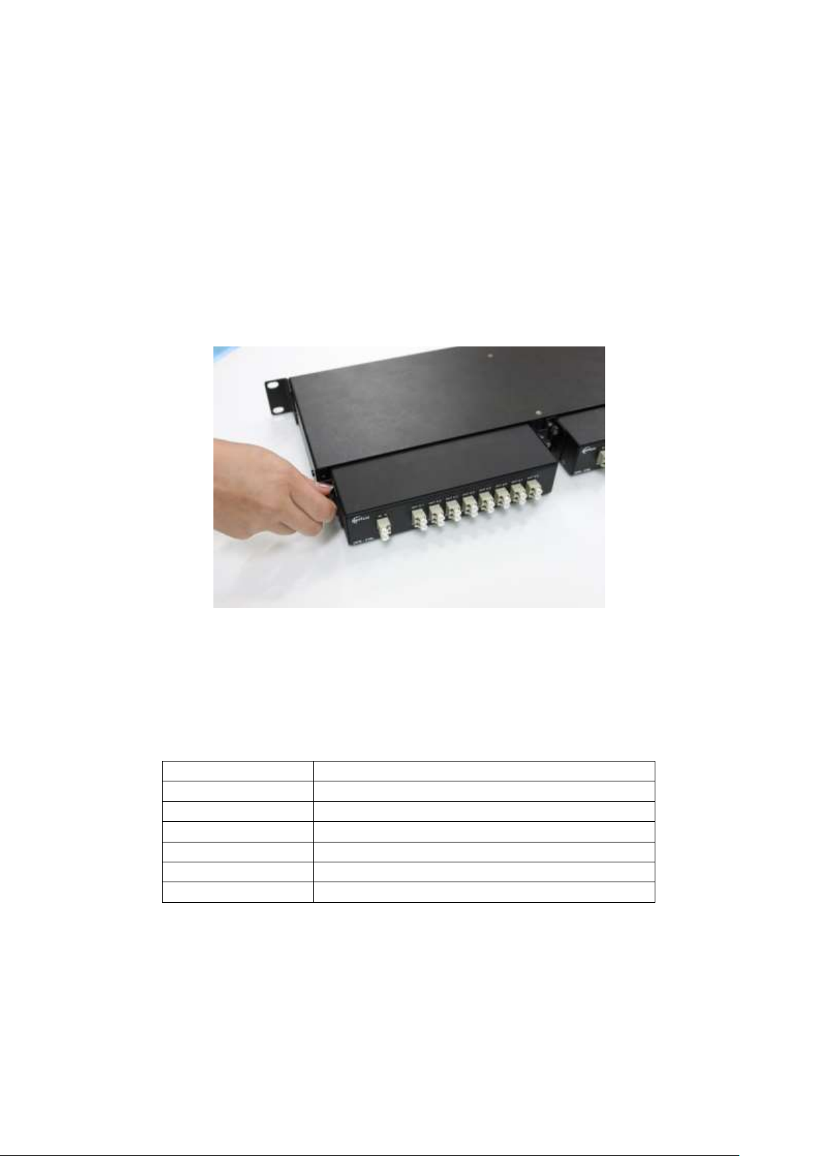
Plug optical passive splitter, OPS-216L to any slots of back side of OPSR-2 and fasten it by thumb
screw.
Fig. 5: Plug & Fasten of OPS-216L
※ Refer to the following configuration of optical passive splitter, OPS-xyz.
x (1 digit): The number of input fibers (1, 2, 4)
y (2 digits): The number of output fibers (04, 08, 16)
z: Connector type (S: SC connector, L: LC connector)
[Note] DVFX-110 can be used with OPS-xzS (SC connection type) and M1-201DA-TR, M1-
203D-TR and M1-3R2VI-DU can be used OPS-xyL (LC connection type).
Step 2
Take two (2) caps out of the receptacle of IN A and IN B.
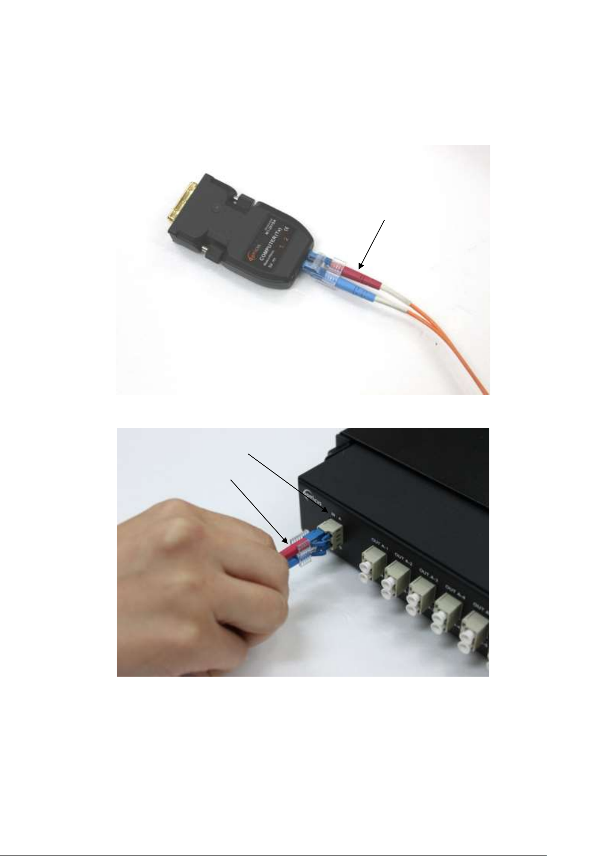
Connect M1-201DA-T (transmitter) and the OPS-216L input LC receptacle (IN A & IN B) over duplex
LC patch cord as shown in Fig. 6 & 7.
- 3 -
Page 4
Red fiber
Red fiber
IN A
Fig. 6: Connect LC patch cord into M1-201DA-T (Transmitter)
Fig. 7: Connect LC patch cord into input receptacle
[Note] In this case, please make sure the optical output signal #2 of M1-201DA-T is transmitted
by red fiber and connected into upper row of OPS-216L input receptacle (IN A).
Step 3
Take all caps out of the output receptacles (from OUT A-1 to OUT B-8).
- 4 -
Page 5

Connect M1-201DA-R (receiver) and the OPS-216L output LC receptacle (OUT A-1 & OUT B-1) over
Red fiber
duplex LC patch cord as shown in Fig. 8 & 9.
Fig. 8: LC patch cord into output receptacle
Fig. 9: Connect LC patch cord into M1-201DA-R
[Note] In this manner, output port #2 of M1-201DA-T is distributed by OPS-216L and connected
to input port #2 of M1-201DA-R over red fiber.
Connect another M1-201DA-R (receiver) and the output LC receptacle (OUT A-2 & OUT B-2) over
duplex LC patch cords as described above and repeat it as many as you need.
Step 4
Connect M1-201DA-T (transmitter) to video source such as PC and connect all M1-201DA-R (receiver)
into each monitor.
[Note] If you are not familiar with fiber optic extenders such as M1-201DA-TR, please refer to
each user manual.
- 5 -
Page 6

Opticis Locations
HQ
16Fl. Kins Tower, 8 Seongnam-daero, 331 beon-gil,
Bundang-gu,
Seongnam-si, Gyeonggi-o, 463-844
Rep. of KOREA
Tel: +82 (31) 719-8033
Fax: +82 (31) 719-8032
For order support, please contact your Distributor or Reseller.
For technical support, visit Opticis web site, www.opticis.com or contact [email protected]
- 6 -
 Loading...