

opticis OMM-2500 User Manual
User’s Manual Version 1.0
OMM-2500
Multi-format Modular matrix
32x32 DVI / HDMI / SDI Matrix
Doc No. : OM-D140805 / Rev1.0

2
TABLE OF CONTENTS
Chapter 1. Introduction and installation ................................................................................................ 4
1.1 Key features.............................................................................................................................4
1.2 Shipping group.........................................................................................................................5
1.3 Notice of safe usage................................................................................................................6
1.4 Physical description.................................................................................................................6
1.5 Installation................................................................................................................................7
1.5.1 Initialization ......................................................................................................................... 7
1.5.2 Connection for remote control ............................................................................................ 7
1.6 EDID Configuration..................................................................................................................7
Chapter 2. Control setup ....................................................................................................................... 9
2.1 TCP/IP.....................................................................................................................................9
2.1.1 TCP/IP setup of PC ............................................................................................................. 9
2.1.2 Launching Telnet ................................................................................................................ 9
2.2 RS-232..................................................................................................................................10
2.2.1 Launching HyperTerminal ................................................................................................. 10
Chapter 3. Control operation .............................................................................................................. 11
3.1 Home & State........................................................................................................................11
3.2 LINK mode.............................................................................................................................12
3.2.1 All Link............................................................................................................................... 13
3.2.2 All Unlink ........................................................................................................................... 13
3.3 Configuration mode...............................................................................................................14
3.3.1 Channel Name .................................................................................................................. 15
3.3.2 LAN & RS232 .................................................................................................................... 16
3.3.3 Multi Viewer ...................................................................................................................... 17
3.3.4 Video Generator ................................................................................................................ 18
3.3.5 Monitoring Port .................................................................................................................. 19
3.3.6 EDID Management ........................................................................................................... 20
3.3.7 HDCP on/off ...................................................................................................................... 24
3.3.8 Preset ................................................................................................................................ 25
3.3.9 Control Lock ...................................................................................................................... 28
Chapter 4. PC program operation ....................................................................................................... 29
4.1 PC program file download and Installation............................................................................29
4.2 Connect Info..........................................................................................................................30
Chapter 5. Web control panel operation ............................................................................................. 31
Chapter 6. Command input operation................................................................................................. 32
6.1 Command input structure......................................................................................................32
6.2 Examples of command inputs................................................................................................33
6.2.1 Link input and output ......................................................................................................... 33
6.2.2 Input and output status ..................................................................................................... 33
6.2.3 Input and Output Name request and setting ..................................................................... 34
Table 6.4 Input and Output Name request and setting command examples ................................ 34
6.2.4 Network setting ................................................................................................................. 34
6.2.5 Video generator setting ..................................................................................................... 35
6.2.6 Monitor output port setting ................................................................................................ 36
6.2.7 EDID control command ..................................................................................................... 37
6.2.8 HDCP On off setting ......................................................................................................... 37

3
6.2.9 Baud rate setting for RS-232 ............................................................................................ 38
6.2.10 Multi-viewer card (QDVI-O) setting ................................................................................... 38
6.2.11 Slot status request ............................................................................................................ 39
6.2.12 Control lock command ...................................................................................................... 40
6.2.13 Preset Control Commend ................................................................................................. 41
6.2.14 Power State Request ........................................................................................................ 42
6.2.15 Firmware Version Request ............................................................................................... 42
Chapter 7. Firmware update ............................................................................................................... 43
Chapter 8. Trouble shooting ............................................................................................................... 46
Chapter 9. Specification ...................................................................................................................... 47
9.1 General Specification.............................................................................................................47
9.2 Power Specification...............................................................................................................48
9.3 SDI video input and output scaling condition.........................................................................48
9.4 Compatibility between Dual link DVI In/Output cards and another In/Output cards..............49
Chapter 10. Warranty Information ...................................................................................................... 50
Chapter 11. Safety Instructions .......................................................................................................... 51
Chapter 12. Maintenance ................................................................................................................... 52

4
Chapter 1. Introduction and installation
Purpose
The modular matrix, OMM-2500 enables to connect between various video sources and displays and
it offers flexible installation with other video controllers or control software. The input and output cards
are composed of 4 ports, therefore user can easily configures any input and output channels from 4X4
to 32X32 by plugging the cards into OMM-2500 mainframe.
Introduction
The OMM-2500 modular matrix enables to switch up to 32 different DVI, HDMI and SDI sources to 32
different digital displays. It can be configured using 8 input and output cards and each card has 4 ports
of input and output. In case of Dual link DVI card (DDVI-2EI / DDVI-2EO), it is composed of 2 ports,
therefore configuration for input and output channels are from 2x2 to 16x16.
Any input source, whether it is a HD-DVD player, Blue-Ray player or a computer with high-resolution
graphics, can be routed to DVI and HDMI output digital display.
Note) SDI is not a licensed HDCP interface and if the content received from HDMI is protected by
HDCP, there should be no output from the SDI slot.
1.1 Key features
▪ Up to 32 DVI, HDMI and SDI inputs and outputs can be configured.
▪ Each card has 4 input or 4 output ports and 8 cards can be fitted into input and output bays.
Dual link DVI supports from 2 x 2 to 16 x16 input and output.
▪ Has Electrical DVI, HDMI, SDI and Optical DVI input and output cards.
▪ Provides Touch LCD and a user-friendly graphic interface.
▪ Any input formats can be converted to DVI, HDMI and SDI. But the resolution between the
formats should be same.
▪ Complies with DDC/HDCP (Electrical DVI and HDMI cards only).
▪ Supports up to WUXGA (1920x1200) at 60Hz refresh ratio for Single link DVI, WQXGA
(2560x1600) at 60Hz refresh ratio for Dual link DVI or 1080p at 60Hz for HDMI and SDI.
▪ Supports 4 types of EDID management:
Default Mode.
Auto Detect Mode.
Output Copy Mode.
Resolution List Mode.
▪ Supports various control methods:
Touch control operation

5
Key buttons operation
Command input (Such as Hyper terminal by RS-232 and Telnet by TCP/IP)
Web panel control (TCP/IP)
PC program by RS-232 and UDP
▪ Works with OPTICIS DVI, HDMI, and SDI optical extender for long signal extension.
▪ Has dual-power supplier for hot-swappable and load-sharing.
▪ Equips multi-viewer card to be used in various monitoring systems.
▪ Provides Preset mode to save and load the current routings.
▪ Provides diagnostic function for quick trouble shooting.
▪ Has video generator output and monitoring output for easy installation.
1.2 Shipping group
▪ OMM-2500, Modular matrix chassis: 1 EA
▪ Input / output cards: Option
SDVI-4EI, 4 ports electrical Single link DVI input card
SDVI-4EO, 4 ports electrical Single link DVI output card
DDVI-2EI, 2 ports electrical Dual link DVI input card
DDVI-2EO, 2 ports electrical Dual link DVI output card
SDVI-1FI, 4 ports 1 fiber optical DVI input card
SDVI-1FO, 4 ports 1 fiber optical DVI output card
HDMI-4EI, 4 ports electrical HDMI input card
HDMI-4EI, 4 ports electrical HDMI output card
SDI-4EI, 4 ports electrical SDI input card
SDI-4EO, 4 ports electrical SDI output card
QDVI-O, Multi-viewer card
▪ AC power cord: 1EA
▪ Power supplier: 1 EA (Dual power supplier is an option)
▪ User manual: 1 EA
▪ Firmware download cable: 1 EA (Use only this accessory specified by the manufacturer)
▪ RS-232 cable (Straight type): 1 EA
6
1.3 Notice of safe usage
We recommend you to read following warning, precaution and information before start to
operate the OMM-2500 modular matrix.
▪ Use of the equipment in a manner not specified by the manufacturer may result in ire-
coverable damage.
▪ Keep the unit away from liquid, magnetic and combustible substances.
▪ Do not place heavy weight on the unit.
▪ Move away from noisy environment such as vibration or impact.
▪ Do not install the unit vertically. / Do not disassemble the unit.
▪ Carry the unit using the handle in front of the panel with two (2) Users.
1.4 Physical description
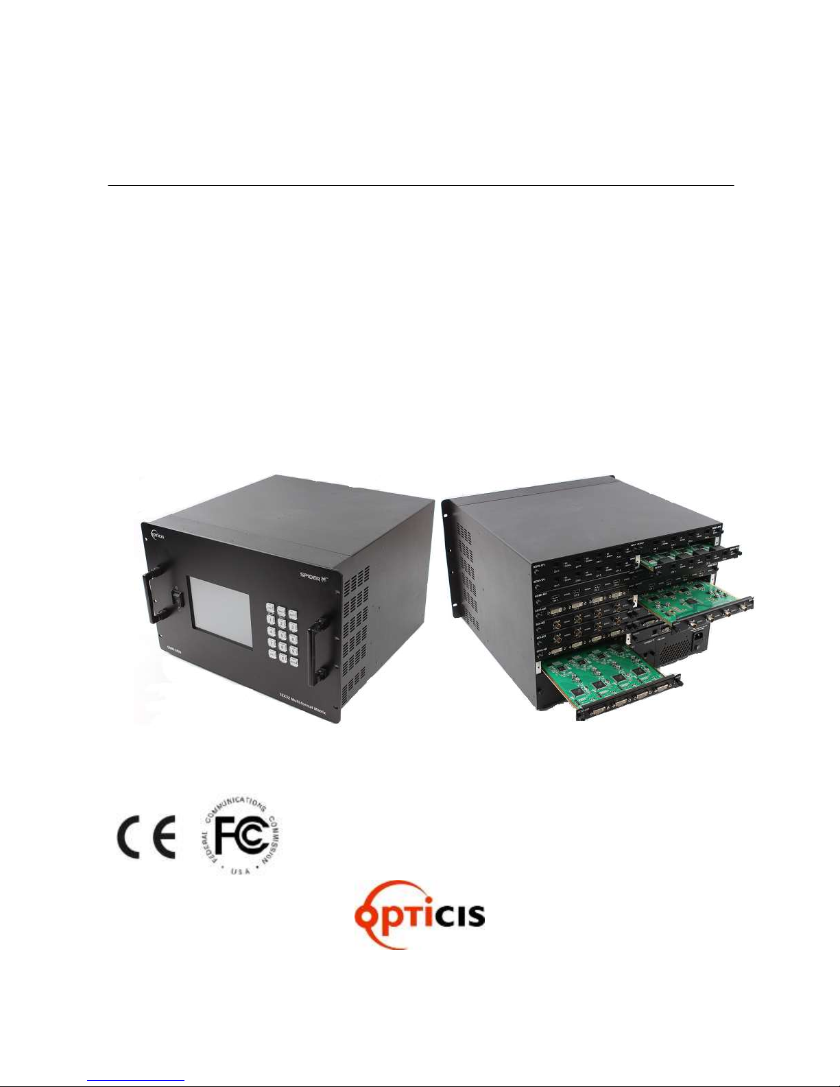
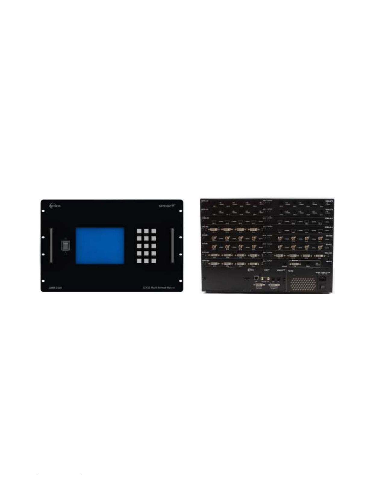
The OMM-2500 modular matrix chassis is mountable on a 19” standard rack. Key buttons,
LCD display and power switch are placed on the front panel as shown in Figure 1-1.
Figure 1-1 Front and Rear panel of OMM-2500
All Input and output cards, interface ports and power supplier are placed on the rear panel as
below.
▪ Input bay for 4 input cards (left side)
▪ Output bay for 4 output cards (right side)
▪ RS-232 / F1, Serial communication and Main Firmware port
▪ F2, Input Firmware port
▪ F3, output Firmware port
▪ LAN, RJ-45 receptacle for TCP/IP or UDP control
▪ REFERENCE OUTPUT for internal video source for easy installation
▪ MONITORING OUTPUT for internal output port to monitor input signal
▪ Power supplier (Dual-power is an option)

7
1.5 Installation
1.5.1 Initialization
▪ Put insert the cards into each input or output bay according to user interface.
▪ All input or output cards have the same connection way, and tighten the screws just until
snug against the main frame. Then, please make sure the cards are fully seated.
▪ Connect the provided AC power cord to AC power inlet. Turn on the switches at the bottom
of the AC power inlet and on the front panel step by step. Then, OMM-2500 will start
initialization process.
▪ ‘Loading’ will be shown on LCD display.
▪ After 7~10 sec, Home & State status on LCD display will be shown.
▪ Now, OMM-2500 is ready to receive commands from user.
1.5.2 Connection for remote control
▪ Connect the OMM-2500 to PC with the supplied RS-232 cable.
▪ Connect the OMM-2500 to PC with LAN cable with RJ-45 connector.
[NOTE] Typically, the IP address of PC connected to the network is configured by DHCP
server. But, if the PC is connected directly to the OMM-2500, the network server will
not able to assign the IP address. In this case, network information of PC should be
set manually.
The default IP address of OMM-2500 is 192.168.1.117. Before connecting OMM2500 to your network, please verify the availability of IP address in your network.
The IP address can be reconfigured by key button, PC program or command lines
over RS-232 or TCP/IP.
1.6 EDID Configuration
▪ EDID (Extended Display Identification Data) is an information set that is provided by a
display to describe its capabilities to a graphic source. It enables a graphic source to identify
the connected display.
▪ The information set includes: manufacturer, product type, phosphor or filter type, timings
supported by the display, display size, luminance data and (for digital displays only) pixel
mapping data.
▪ Once the graphic source reads the information set (usually during the booting process), the
EDID determines the optimal format for a connected display.
▪ OMM2500 supports storing of EDID information to an EEPROM for each Input.

8
EEPROM1
EEPROM2
EEPROM3
EEPROM32
EDID
INTERFACE
CONTROL
Read/Write
Sources
INPUT 1~32
Displays
OUTPUT 1~32
WRITE EDID
.
.
.
.
.
.
.
.
▪ OMM2500 has four-way EDID settings, 1) Default Mode: default EDID from the factory, 2)
Output Copy Mode: read of EDID from any target display and copy in input port 3) Auto
Detect Mode: analyzing of all EDID from the attached displays and store optimized EDID in
input port to avoid any compliance problems in the field and 4) Resolution List Mode: read
EDID from the selected Resolution List by user and copies it in allocated input.
Figure 1-2 Concept of EDID setting and working in OMM-2500 modular matrix
As depicted in Figure 1-2, once EDID is configured, each EDID is stored in EEPROM in Input
ports. As a result, the video sources are able to read EDID from the EEPROM during booting
process even though the OMM-2500 and connected displays are not powered on yet.

9
Chapter 2. Control setup
The OMM-2500 modular matrix can be controlled in various ways such as command input (RS-232,
TCP/IP), Web control panel (TCP/IP), supplied PC program (RS-232, UDP) as well as Touch LCD
and key button on the front panel. To do this, PC should be configured properly.
2.1 TCP/IP
2.1.1 TCP/IP setup of PC
TCP/IP, the abbreviation of Transmission Control Protocol (TCP) and the Internet Protocol (IP)
is commonly used protocol to control remote computers.
To control OMM-2500 over TCP/IP, set network properties of PC as below (Explained here is
based on Win 7 OS).
▪ Open Control Panel.
▪ Select Network Status in Network and Internet menu.
▪ Select Adapter setting.
▪ Select Local Area Connection and right click to open property.
▪ Select Internet Protocol Version 4 (TCP/IPv4)
▪ Enter IP, Subnet mask, Gateway and DNS server address, compatible with the current
network setting of OMM-2500.
▪ Click OK to terminate IP setup session.
[Note] If the IP address of OMM-2500 is 192.168.001.117, the PC IP address should be
chosen as 192.168.001.nnn; where ‘nnn’ can range from 000 to 255 except 117.
2.1.2 Launching Telnet
Telnet is a terminal program embedded in Window OS system to access remote computers
using TCP/IP protocol. With the network setting of the PC as above, launch Telnet as below.
▪ Make sure PC and OMM-2500 are connected by Ethernet.
▪ Click Start menu and select Run.
▪ Type CMD to open command window.
▪ Type ‘telnet 192.168.1.117’ (Type current IP address of OMM-2500).
▪ Press ENTER then, “==Welcome to OMM-2500==” and “== TELNET control ==”
messages will be shown.
▪ Type command inputs to control OMM-2500. (Refer to Chap. 6)

10
2.2 RS-232
2.2.1 Launching HyperTerminal
The OMM-2500 modular matrix provides RS-232 serial communication. The simplest way to
control OMM-2500 over RS-232 is using embedded software in Windows OS, HyperTerminal.
To launch Hyper Terminal (Explained here is based on Windows XP OS. Hyper Terminal is
not available on Win 7.):
▪ Connect the PC to OMM-2500 over RS-232 cable.
▪ Select Start > Programs > Accessories > Communications > HyperTerminal.
▪ Enter a name and choose an icon in Connection Description window and click OK.
▪ In Connect To window, ignore the Country, Area Code and Phone Number fields but select
available COM port of PC to be connected to OMM-2500 then, click OK.
▪ In COM Properties window, set the parameters as below:
Bits per second (baud rate): 115200 (115200 is default baud rate of OMM-2500)
Data bits: 8
Parity: None
Stop bits: 1
Flow control: None
[Note] Bit per second of Hyper Terminal should be set as same as baud rate of OMM-2500.
▪ Click OK to save the parameters.
▪ Go Start > Programs > Accessories > Communications > HyperTerminal, then new icon
will be shown. Then select it to launch Hyper Terminal.
▪ Type command inputs to control OMM-2500 (Refer to Chap. 5)

11
Section
Remark
Section
Remark
Home & State icon
F/W MAIN
Current Firmware
version
Power Status icon
Sub-I
Current Input card
Firmware version
Link Mode icon
Sub-II
Current output card
Firmware version
Configuration Mode
icon
RS232,IP
Current Network
Setting status
3.1 Home & State
▪ It provides a user-friendly graphic interface showing various status, such as input/output card
type, connection, power on/off, firmware version and network information.
▪ If the green LED of output slot number is lit ON as shown above, user can recognize the
resolution of input signal (ex. CH21=800x600) and input/output connection status.
▪ If LED is OFF, input and output signals are not connected and it will be disable as grey color.
▪ Description of Icons
Chapter 3. Control operation
12
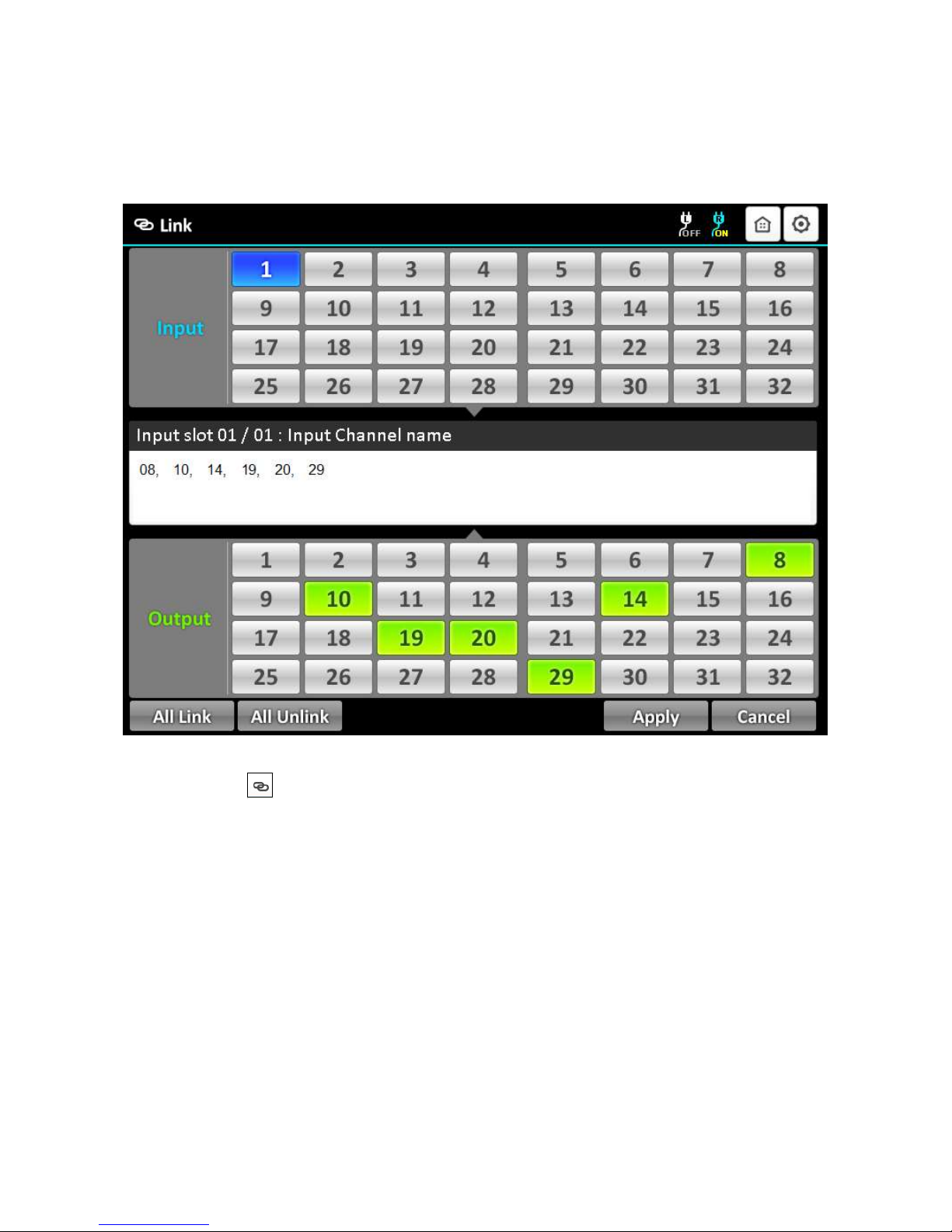
3.2 LINK mode
▪ It configures input/output connections for cross-switching.
1) Touch , the Link Icon.
2) Touch an input channel to be designated among 32 input buttons.
3) Touch single or multiple output channel(s) among 32 output buttons to be connected with
display.
4) Outputs can be initialized by clicking designated output button again.
5) Touch Apply button to save the configuration.
6) Touch the selected input button again to check current input number/channel name and
connected output.
7) To configure next Input / output connection, repeat from step 2 to 4.

13
3.2.1 All Link
▪ It connects an input and all output connection.
1) Touch All Link icon.
2) Touch an input channel button to select desired input.
3) Touch Apply button to save the configuration.
4) Touch selected input channel again to check the connection between the selected input
and connected all output.
3.2.2 All Unlink
▪ It unlinks connected input and output channel(s).
1) Touch All Unlink button.
2) Touch an input channel button to select desired input.
3) Touch Apply button to save the configuration.
4) Touch the selected input channel again to check an unlink state between the selected input
and connected output(s).
14
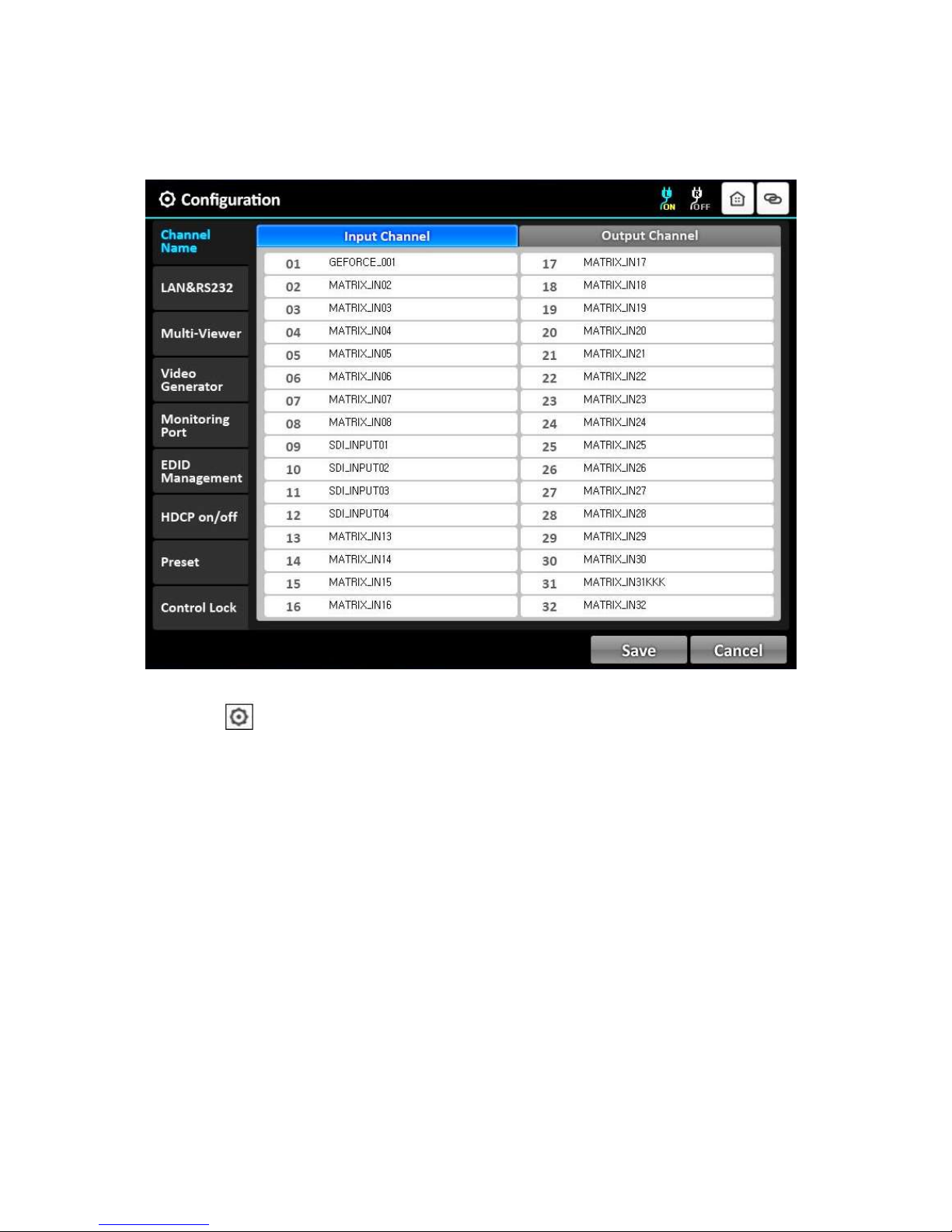
3.3 Configuration mode
▪ It provides basic configuration of OMM-2500.
▪ Touch , configuration icon to see all features.
Channel Name
LAN & RS232
Multi-Viewer (It is activated when QDVI-O is in output bay)
Video Generator
Monitoring Port
EDID Management
HDCP on/off
Preset
Control Lock
15
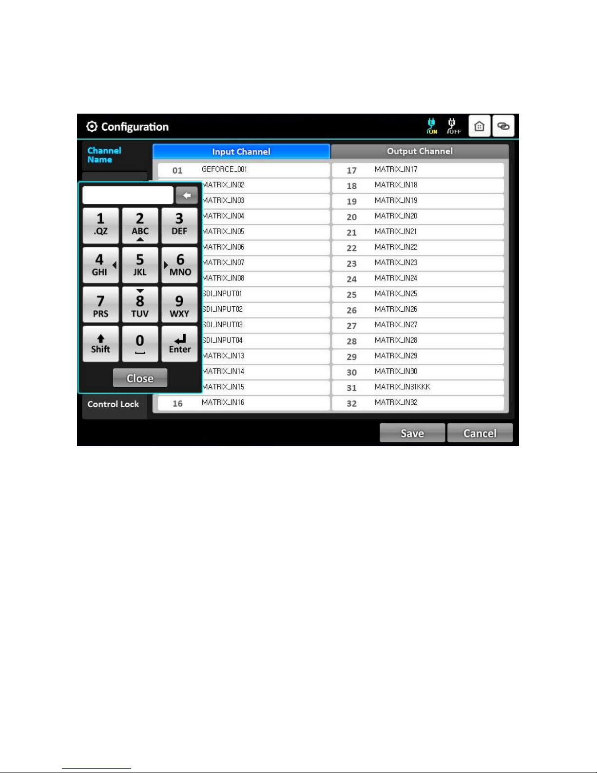
3.3.1 Channel Name
▪ It can be allocated specific names for all inputs and outputs to distinguish them.
▪ Touch Input channel or Output Channel bar right next to Channel Name.
▪ Touch a channel bar to enter channel name.
▪ Then, the keypad window will be popped up.
▪ Touch Shift key to select a letter or number and ‘0’ button to make a space.
▪ Enter a channel name using the keypad.
▪ Touch Enter key, then keypad will be closed.
▪ Touch the Save button to complete the process.
16
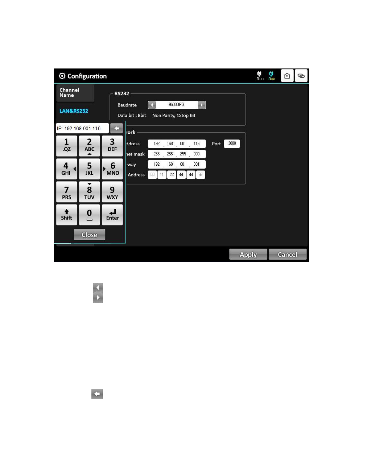
3.3.2 LAN & RS232
1) Baud rate:
▪ It sets RS-232 Baud Rate. OMM-2500 supports 9600, 19200, 38400, 57600 and 115200bps.
▪ Touch icon to decrease Baud Rate.
▪ Touch icon to increase Baud Rate.
▪ Touch Apply icon to complete the process.
▪ The default setting is 115200.
2) Network:
▪ It modifies IP Address, Subnet mask, Gateway, Mac Address and Port to be used for your
network.
▪ Touch one (1) of them to modify the network setting.
▪ LED shows the keypad window.
▪ Touch the number key to enter desired setting.
▪ Touch the Shift icon to move the next row.
▪ Touch the icon to modify the number.
▪ Touch the Enter key.
▪ Touch the Apply icon to save the configuration.
 Loading...