

Page 1

Edition:2A
OHM - 88
HDMI Matrix Router
USER MANUAL
Page 2
USER MANUAL
HDMI MATRIX ROUTER OHM-88
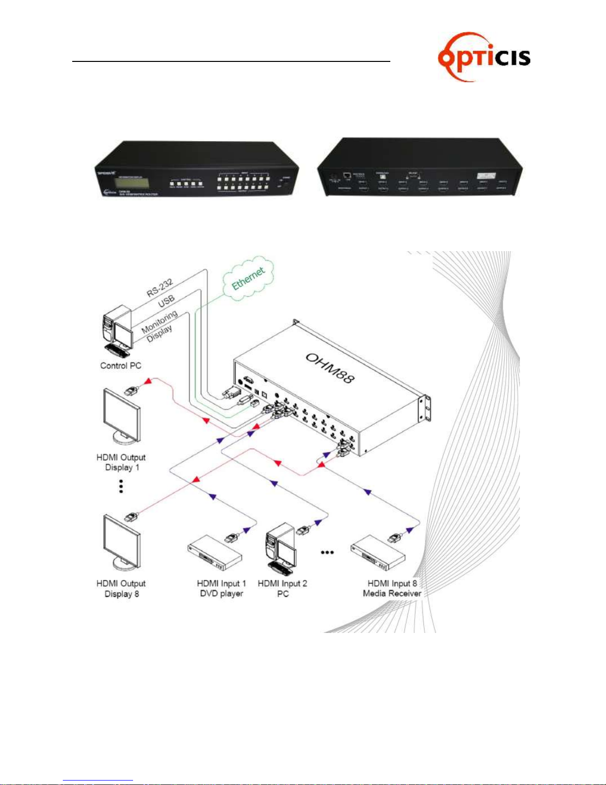
<OHM-88 FRONT> <OHM-88 REAR>
OHM-88 Manual Page 2
Page 3

USER MANUAL
HDMI MATRIX ROUTER OHM-88
Table of Contents
1 Introduction and Installation………………………………………………………………………. 5
1.1 Key features………………………………………………………………………………………... 5
1.2 OHM-88 Shipping Content………………………………………………………………………... 5
1.3 Safety Instructions…………………………………………………………………………………. 6
1.4 Physical Description………………………………………………………………………………. 6
1.4.1 Front Panel………………………………………………………………………….……….. 7
1.4.2 Rear Panel………………………………………………………………….……….….……. 7
1.5 EDID Control and Configuration …………………………………………………………………. 8
1.6 Connecting Optical HDMI cables and modules for extended distance……………………… 9
1.7 Initializing OHM-88 and Installation Guide………………………………………………………. 9
1.7.1 Initialization………………………………………………………………………………….. 9
1.7.2 Rack Mounting……………………………………………………………………………… 10
1.7.3 Control Connection………………………………………………………………………… 10
1.7.4 RS-232 Control……………………………………………………………………………... 10
1.7.5 Ethernet Control…………………………………………………………………………….. 10
1.7.6 Direct connection of PC or video controller to the OHM-88: Use a crossover
Ethernet cable.…………………………………………………………………………… 10
1.7.7 LAN connection of OHM-88: Direct Ethernet connection…………………………….. 10
2 Communications Setup……………………………………………………………………..…… 10
2.1 Setting the Router ID of OHM-88………………………………………………………………… 10
2.2 Front Panel Interface……………………………………………………………………………… 11
2.3 CREATE Mode……………………………………………………………………………………. 11
2.4 PREVIEW Mode………………………………………………………………………………….. 11
2.5 CANCEL Mode…………………………………………………………………………………… 12
2.6 FUNCTION Mode………………………………………………………………………………… 12
Press FUNCTION to view features – pressing FUNCTION repeatedly will cycle the
following Features…...…………………………………………………………………………... 12
2.6.1 EDID Read/Write: press FUNCTION key once………….……………………………. 12
2.6.2 MONITOR OUTPUT SELCTION – To verify the video source press FUNCTION
two times .………………………………………………………………………………….. 13
2.6.3 RS-232 BAUD RATE: press FUNCTION three times…………………………………. 13
2.6.4 Gateway: press FUNCTION four times………………………………………………… 13
2.6.5 Subnet Mask: press FUNCTION five times …………………………………………… 14
2.6.6 IP Address: press FUNCTION six times………………………………………………… 14
2.6.7 MAC Address: press FUNCTION seven times…………………………………………. 14
2.6.8 Port Number: press FUNCTION eight times……………………………………………. 15
2.6.9 FACTORY MODE: press FUNCTION nine times……………………………………… 15
2.7 Serial Communication…………………………………………………………………………… 15
2.7.1 HyperTerminal…………………………………………………………………………….. 15
2.7.2 Telnet ……………………………………………………………………………………… 18
2.7.3 Launching Telnet Session ………………………………………………………………. 18
2.8 Ethernet Control…………………………………………………………………………………. 19
2.8.1 SETTING THE IP ADDRESS of the PC………………………………………………… 19
3 Operation………………………………………………………………………………………… 21
3.1 Front Panel Operation…………………………………………………………….…………….. 21
3.2 Command Line Operation………………………………………………………………………. 23
3.2.1 Create……………………………………………………………………………………… 25
3.2.2 Preview: Shows all Input-Output configurations……………………………………… 26
3.2.3 Cancel: Cancels configuration of outputs for each Input……………………………. 26
3.2.4 Upload Data Request: Uploads connection data to the controller…………………. 27
OHM-88 Manual Page 3
Page 4

USER MANUAL
HDMI MATRIX ROUTER OHM-88
3.2.5 Rolling command………………………………………………………………………… 27
3.2.6 Upload Router ID………………………………………………………………………… 29
3.2.7 Rolling Stop……………………………………..…………………………………………. 29
3.2.8 Check Connection …………………………………………………………………………. 29
3.2.9 Upload One Channel Data Request…………………………………………………….. 30
3.2.10 Read Output Device EDID ……………………………………………………………….. 30
3.2.11 Read Input EEPROM EDID……………………………………………………………… 31
3.2.12 EDID Write…………………………………………………………………………………. 31
3.2.13 Default EDID Setting……………………………………………………………………... 32
3.2.14 Baud rate Setting…………………………………………………………………………. 32
3.2.15 Monitoring…………………………………………………………………………………. 33
3.3 Proprietary PC Software Installation ……………………………………….…………….…… 34
3.3.1 Installation of PC Application…………………………………………………………… 34
3 .4 Proprietary PC Software Operation…………………………………………………….....….. 36
3.4.1 PC Operation using RS-232………………………..…………………………………… 36
3.4.2 PC Operation using Ethernet ……………………………………….…………………. 42
3.4.3 Sytem Menu………………………………………………………………………….…… 48
3.4.4 Function Menu……………………………………………………………………….…… 49
3.4.5 Title Folder – Initial screen of PC Software………………………….………….……. 50
3.4.6 Matrix Control Folder…………………………………………………………...………. 51
3.4.7 EDID Folder……………………………………..……………………………...….……. 52
3.5 Matrix Control Operation………………………………………………………………………. 53
3.5.1 Select Input Chanel……….………………………..…………………………….……… 53
3.5.2 Easy link for Input CH to all Output CH ……………….………….………..…………. 56
3.5.3 Select Monitoring..…………………………………………………………….………… 57
3.5.4 Save Switching Pattern………………………………………………………..………… 58
3.5.5 Rolling Function ………………………………….…………………….……..…………. 60
3.5.6 Select Rolling Mode……………………………………………………………..………. 61
3.5.7 Pattern Rolling Mode……………………………………………………………..……... 61
3.6 EDID Setting……………………………………………………………………………..……… 62
3.6.1 Features………………………………………………………………………….………. 62
3.6.2 Importance of EDID – Example…………………………………………………..….... 62
3.6.3 Setting EDID……………………………………………………………………….…….. 62
3.6.4 Write EDID data of Output Device to Input CH EEPROM…………………….…..… 63
3.6.5 Read EDID…………………………………………………………………………...…… 64
3.6.6 Write the read EDID Data……………………………………………………………….. 65
3.6.7 Save the edited EDID Data and open the saved file…… ……………………...….… 66
3.6.8 EDID EDITOR……………………………………………………………………..…..…. 67
4 Troubleshooting………………………………………………………………………….……… 69
5 Features………………………………………………………………………………….....……. 70
6 Specification…………………………………………………………………………………..…. 70
7 Firmware downloading……………………………………………………………………..….… 71
OHM-88 Manual Page 4
Page 5
USER MANUAL
HDMI MATRIX ROUTER OHM-88
1 Introduction and Installation
OHM-88 is a high speed cross-switch with 8 HDMI inputs and 8 HDMI outputs housed in a ruggedized metal enclosure to protect against harsh environments.
1.1 Key features:
Eight (8) HDMI single-link inputs and outputs
Pixel resolution up to WUXGA (1920x1200) @ 60Hz refresh ratio – with 1.65Gbps trans-
mission bandwidth
Dynamic EDID management – adapts to overall power management of the system
Restores the default EDID to Input port
Reads EDID from display and stores EDID to Input port via EEPROM
Long distance extension of HDMI Input and Output by Optical HDMI cables or modules
Re-Clocking of R,G,B of HDMI inputs and outputs
Various Control Interfaces:
Front panel key input
Input commands through RS232 and LAN
Graphical user interface using Ethernet and Proprietary PC software in the shipped
system
Hierarchical connection of multiple OHM-88 - up to 3 levels to increase the number of
display connections or source connections
DIP switch for up to 255 different ID settings for multiple use of OHM-88 over RS232
connection
IP setting for Ethernet – point-to-point and local network control
1.2 OHM-88 Shipping Content:
OHM-88 Mainframe: 1 EA
Firmware download cable(USB):
AC/DC power adaptor (12V/5A,
AC110V-240V): 1 EA
AC power cord: 1 EA
User Manual: 1 EA
PC control software CD: 1 EA
OHM-88 Manual Page 5
1 EA
RS-232 cable (crossed type): 1 EA
RJ-45 UTP cable (crossed type):
1 EA
Rack ear: 2 EA
Page 6

USER MANUAL
HDMI MATRIX ROUTER : OHM-88
1.3 Safety Instructions
Use of the equipment in a manner not specified by the manufacturer may result in irre-
coverable damage.
Use the assigned power cord or power adaptor shipped with the system.
Connect the power cord to the normal and safe outlet.
Keep the unit away from liquid, magnetic and combustible substances.
Do not place heavy weight on the unit.
Move away from noisy environment such as vibration or impact.
Do not install the unit vertically.
Do not disassemble the unit.
When malfunction or breakdown occurs, contact factory immediately.
1.4 Physical Description
1.4.1 Front Panel
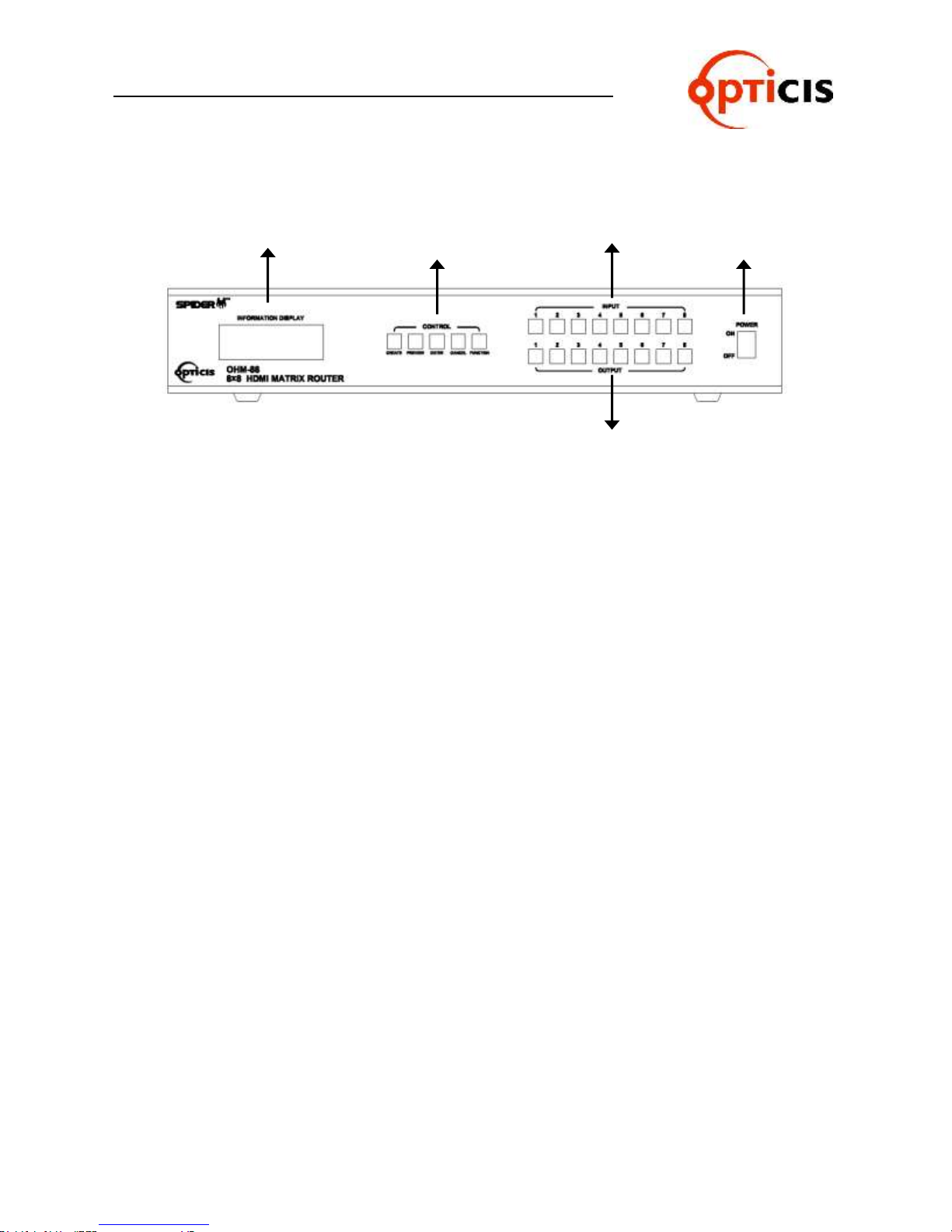
OHM-88 chassis is mountable on a 19” standard rack with rack ears. Control
keys, Input-Output buttons and the status LCD display, are placed on the front
panel as shown in Figure 1-1.
Control keys: ①
CREATE – Configure Input-Output setup
PREVIEW – Displays current status of Input-Output configuration
CANCEL - Resets all Outputs configured with an Input or Reject any key in-
puts
ENTER - Accepts keyed inputs and completes configuration of Input-Output
setup
FUNCTION - Configures IP for Ethernet, baud rate for RS232 and EDID
Input-Output Buttons:
Eight (8) LED inputs: ②
Eight (8) LED outputs: ③
Status display: LCD displays the control status in 20x4 text mode: ④
POWER ON/OFF button: ⑤
OHM-88 Manual Page 6
Page 7
USER MANUAL
④
①
②③⑤
HDMI MATRIX ROUTER : OHM-88
<OHM-88>
Figure 1-1 Front Panel
1.4.2 Rear Panel
All Input ports, Output ports, interface ports and power connections are placed on
the rear panel as follows;
Eight (8) single link HDMI inputs: ①
Eight (8) single link HDMI outputs: ②
DIP switch - 8 bits to set ID (identifier) in case of multiple connection of
OHM-88: ③
RS-232 Serial port: ④
10/100 Base Ethernet port: ⑤
Firmware download port: ⑥
DC power receptacle: ⑦
MONITORING HDMI port – monitors a designated source for test purpose:
⑧
[Note] For OHM-88, Output #1 will be disconnected automatically when monitoring port is
connected and working.
OHM-88 Manual Page 7
Page 8

USER MANUAL
③
①
②
④ ⑤ ⑥
⑦
⑧
HDMI MATRIX ROUTER : OHM-88
<OHM-88>
Figure 1-2 Rear Panel
1.5 EDID Control and Configuration
EDID (Extended Display Identification Data) is an information set that is provided by a
display to describe its capabilities to a graphic source. It enables a graphic source to
identify the connected display.
The information set includes: manufacturer, product type, phosphor or filter type, timings
supported by the display, display size, luminance data and (for digital displays only) pixel
mapping data.
Once the graphic source reads the information set (usually during the booting process),
the EDID determines the optimal format for a connected display.
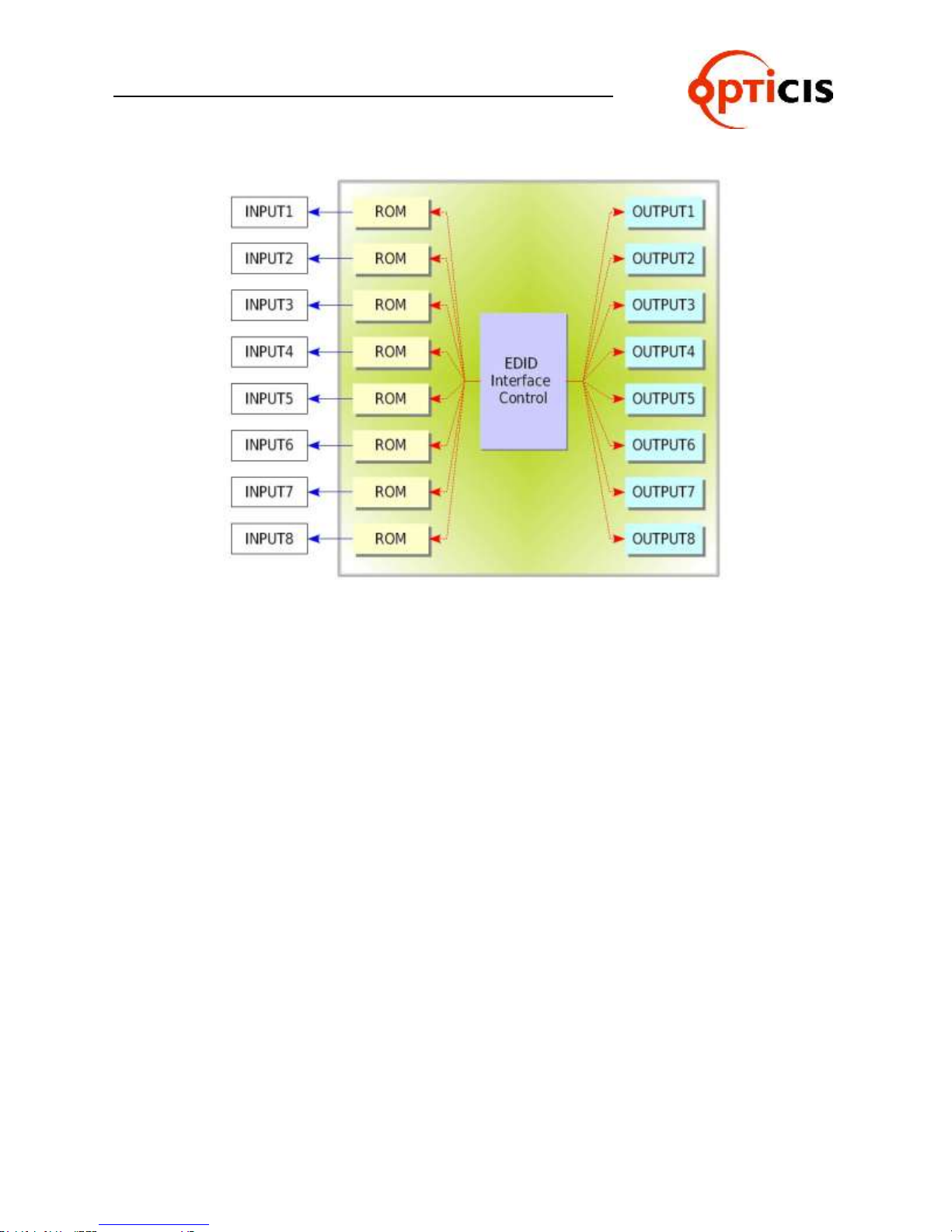
OHM-88 supports storing of EDID information to an EEPROM for each Input by dedicat-
ed PC software.
OHM-88 has two-way EDID settings, default EDID from factory and direct readout of
stored EDID of any target display. The default EDID setting from the factory is 1080p
(1920 x 1080) @ 60Hz for all inputs.
OHM-88 Manual Page 8
Page 9
USER MANUAL
HDMI MATRIX ROUTER : OHM-88
Figure 1-3 Concept drawing for setting EDID in OHM-88
As depicted in Figure 1-3, once EDID is configured, each EDID is stored in EEPROM at
the front of the HDMI Input. As a result, the video sources are able to read EDID from
the EEPROM during boot-up; even though the OHM-88 and connected displays are not
powered on yet.
1.6 Connecting Optical HDMI cables and modules for extended distance
OHM-88 supports connection of Optical HDMI cables or modules to all inputs and outputs.
The use of copper HDMI cables over 3m (10ft.) is not recommended.
1.7 Initializing OHM-88 and Installation Guide
1.7.1 Initialization
1) Plug the provided AC power cord to the AC/DC power adaptor then plug the DC
cord to the +12VDC connector on the rear panel; make sure that the arrow mark
on the connector of the DC cord is aligned.
2) Push POWER button on the front panel then observe:
Red LED (on the button) – will light up
Display – will display “OHM-88……….Initializing”
Green and Red lights on the Input and Output – will sweep on.
Display – will show “USER MODE”
The system is now ready to accept commands.
OHM-88 Manual Page 9
Page 10

USER MANUAL
HDMI MATRIX ROUTER : OHM-88
1.7.2 Rack Mounting
Before installing cables, attach two rack ears on left and right side of OHM-88
using the supplied screws.
1.7.3 Control Connection
Commands and functions of OHM-88 are transferred through the RS-232 and
Ethernet connection.
1.7.4 RS-232 Control
Connect the OHM-88 to a video controller or PC with the supplied RS-232 cable.
1.7.5 Ethernet Control
Connect the OHM-88 to a video controller or PC with the RJ-45 connector/cable.
1.7.6 Direct connection of PC or video controller to the OHM-88: Use a crossover
Ethernet cable.
Typically, a PC is connected to the network and configured for dynamic IP ad-
dress by a network DHCP server. If the PC is connected directly to the OHM-88,
the network server will not be able to address the PC.
In this case, the PC should be manually set in a static IP address. Refer to Set-
ting the PC IP address in Chap. 2.8.1.
1.7.7 LAN connection of OHM-88: Direct Ethernet connection.
OHM-88 is configured at the factory with the default IP address of 192.168.0.88.
Before connecting to your network, verify the IP address on your network.
The IP address can be reconfigured by front key buttons or command lines over
RS 232 and Ethernet.
2 Communications Setup
2.1 Setting the Router ID of OHM-88
If multiple units of OHM-88 with a video controller or PC controller are used, each
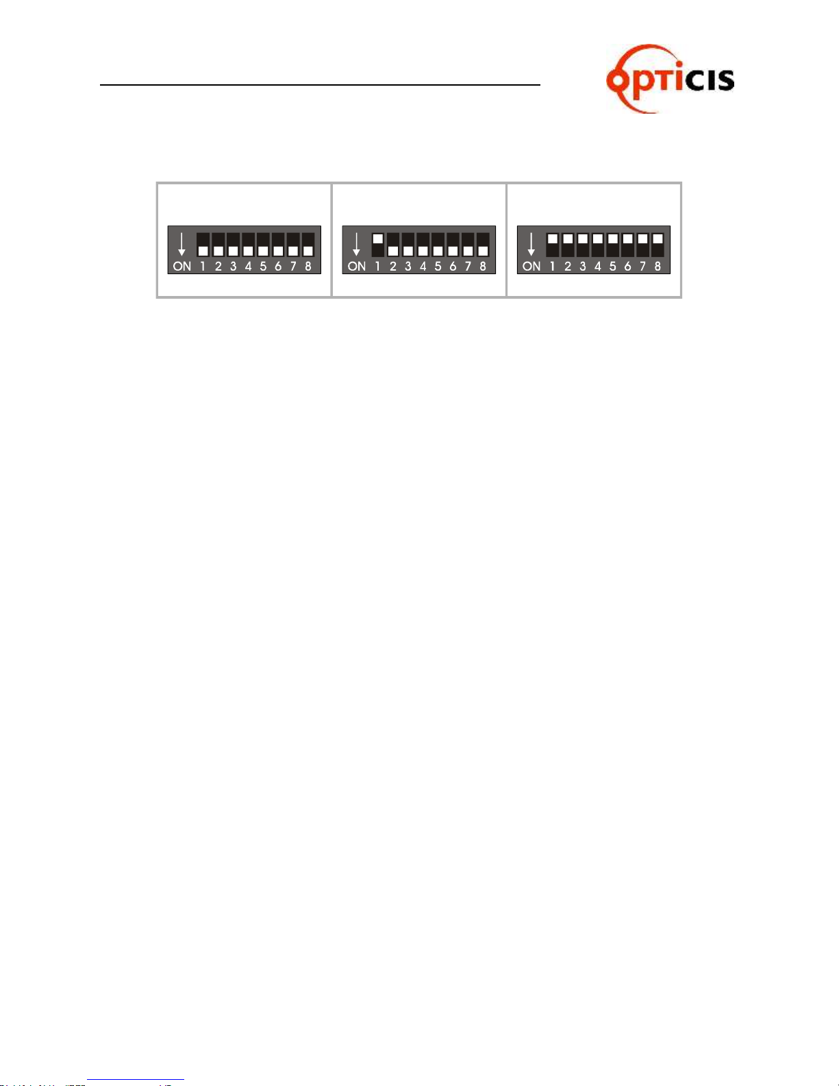
OHM-88 should be identified with the DIP switch located on the rear panel marked as
Router ID. Each DIP switch has 8 digits, one (1) at the up position and zero (0) at the
down position; possible ranges are 000 to 255 and the default factory setting is 255.
OHM-88 Manual Page 10
Page 11
USER MANUAL
In case of 000 In case of 001 In case of 255
HDMI MATRIX ROUTER : OHM-88
Example Setting
All command codes are required to have the Router ID in its header. For more details,
refer to the command code instruction in Chapter. 3.2.
2.2 Front Panel Interface
All communication with OHM-88 is possible using the front input keys - without video
controller or control PC.
Before pressing control keys, make sure that the LCD display shows USER
MODE.
CREATE, PREVIEW and CANCEL keys are activated by pressing each key
- the activated key is executed by pressing ENTER key.
The FUNCTION has the ability to select multiple features on the OHM-88.
Repeatedly pressing the FUNCTION key will display each feature on the LCD
display.
To save the selected feature, press ENTER - to escape current setting, press
another control key; i.e. CREATE or PREVIEW.
2.3 CREATE Mode
Configures Input-Output connections for cross-switching.
1) Press CREATE button once to activate (orange color LED is on) - LCD will display
the current Input and Output configuration.
2) Select and Press an input key (the respective Green LED is on) – LCD will display
current configured Output (Red LED is on).
3) Press single or multiple Output buttons to select desired outputs (Red LED is on for
each selected Output button).
4) Outputs can be deselected by pressing the respective Output button (Red LED is off)
5) Press ENTER to save the selected configuration.
6) To configure the next Input to Output or outputs, repeat steps 1 to 5.
2.4 PREVIEW Mode
PREVIEW mode shows current Input-Output configuration.
1) Press PREVIEW to see current Input-Output connection status on the LCD display.
2) Press any Input button (Green LED is on) to see the current connected Output (indicated by Red LED is on)
OHM-88 Manual Page 11
3) To preview status of another Output, press another Input button.
To see the status of all Input-Output connections, press PREVIEW then ENTER.
Page 12

USER MANUAL
HDMI MATRIX ROUTER : OHM-88
2.5 CANCEL Mode
To Cancel each Input-Output configuration:
1) Press CANCEL then press the desired Input button to be cancelled. The configured
Output buttons LED will be on.
Press ENTER to complete cancellation.
2.6 FUNCTION Mode
Press FUNCTION to view features – pressing FUNCTION repeatedly will cycle
the following features:
EDID Read/Write
Monitor Output Selection
RS-232 Baud Rate
Gateway
Subnet Mask
IP Address
Mac Address
Port Number
Factory mode
2.6.1 EDID Read/Write: press FUNCTION key once
Reads EDID from connected displays and stores information to Input ports
EEPROM.
=========Function Mode========
EDID Read/Write
IN : 1. 2. 3. 4. 5. 6. 7. 8
OUT: 1. 2. 3. 4. 5. 6. 7. 8
IN: INPUT Chanel , OUT : OUTPUT Chanel
Press Front panel INPUT key and choice channel, than choice Output channel
which one need changing.
The Under Bar mark represents selected and activated.(1~8chanel)
Example1: Choice INPUT 1 - OUTPUT 1, INPUT 2 - OUTPUT 2 than Press
Enter Key, will Display 1,2 channel’s EDID Read/Write
Example2: Choice INPUT 1,2,3,4,5,6,7,8 – OUTPUT 1, than Press Enter key,
system will be read the first (1)output channel EDID Data, and write to the
INPUT 1~8 channel EEPROM.
Press ENTER button to complete the configuration, store the information and
execute the process.
OHM-88 Manual Page 12
Page 13

USER MANUAL
HDMI MATRIX ROUTER : OHM-88
2.6.2 MONITOR OUTPUT SELECTION – To verify the video source press FUNCTION
key twice.
1) Connect a display to the MONITORING port and any video sources to the HDMI
Input ports on the rear panel.
2) Press the FUNCTION key once – the LCD displays:
============ Function ===========
Monitor Output sel.
Old Input Channel: 1
New Input Channel:
3) Press Input button of the Input to be monitored.
4) Press ENTER to finish the process.
[Note] For OHM-88, Output #1 will be disconnected automatically when monitoring port is
connected and working.
2.6.3 RS-232 BAUD RATE: press FUNCTION three times
Press Input 1 button for 19200
Press Input 2 button for 38400
Press Input 3 button for 57600
Press Input 4 button for 115200
Press ENTER to complete the process and return to the User mode.
=========Function Mode========
RS-232 Baud Rate
Old Baud Rate: 19200
New Baud Rate: 19200
[Note] Baud Rate of 19200 bps is highly recommended.
2.6.4 GATEWAY: press FUNCTION four times
The Under Bar mark represents selected and activated.
Pressing Input 1 button repeatedly changes the selected number from 0, 1, 2...9.
The Input 2 button decreases the number.
Input 3 and 4 buttons moves the Under Bar left and right.
=========Function Mode========
Gate Way
192. 168. 000. 001
192. 168. 000. 001
Factory setting is 192.168.000.001.
Press ENTER button to complete the process and return to the User mode.
OHM-88 Manual Page 13
Page 14

USER MANUAL
HDMI MATRIX ROUTER : OHM-88
2.6.5 SUBNET MASK: press FUNCTION five times
The Under Bar mark represents selected and activated.
Pressing Input 1 button repeatedly changes the selected number from 0, 1, 2...9.
The Input 2 button decreases the number.
Input 3 and 4 buttons moves the Under Bar left and right.
=========Function Mode========
Subnet Mask
255. 255. 255. 000
255. 255. 255. 000
Factory setting is 255. 255. 255.000.
Press ENTER button to complete the process and return to the User mode.
2.6.6 IP ADDRESS: press FUNCTION six times
The Under Bar mark represents selected and activated.
Pressing Input 1 button repeatedly changes the selected number from 0, 1, 2...9.
The Input 2 button decreases the number.
Input 3 and 4 buttons moves the Under Bar left and right.
=========Function Mode========
IP Address
192. 168. 000. 088
192. 168. 000. 088
Factory setting is 192. 168. 000. 088.
Press ENTER button to complete the process and return to the User mode.
2.6.7 MAC ADDRESS: press FUNCTION seven times
In computer networking, a Media Access Control address (MAC address) is a
unique identifier assigned to most network adapters or network interface cards by
the manufacturer for identification, and used in the Media Access Control protocol sub layer. If assigned by the manufacturer, a MAC address usually encodes
the manufacturer's registered identification number. It may also be known as an
Ethernet Hardware Address (EHA), hardware address, adapter address, or
physical address.
There are three numbering spaces, managed by the Institute of Electrical
and Electronics Engineers (IEEE), which are in common use for formulating
a MAC address:
OHM-88 is shipped with a default MAC ADDRESS. The MAC ADDRESS of
OHM-88 can be edited, however, it is strongly not recommended.
Editing MAC ADDRESS
The Under Bar mark represents selected and activated.
Pressing Input 1 button repeatedly changes the selected number from 0,
OHM-88 Manual Page 14
1, 2...9.
Page 15

USER MANUAL
HDMI MATRIX ROUTER : OHM-88
The Input 2 button decreases the number.
Input 3 and 4 buttons moves the Under Bar left and right.
2.6.8 PORT NUMBER: press FUNCTION eight times
The Under Bar mark represents selected and activated.
Pressing Input 1 button repeatedly changes the selected number from 0, 1, 2...9.
The Input 2 button decreases the number.
Input 3 and 4 buttons moves the Under Bar left and right.
=========Function Mode========
Port Number
Old Data: 03000
New Data: 03000
Factory setting is 03000.
Press ENTER button to complete the process and return to the User
mode.
2.6.9 FACTORY MODE: press FUNCTION nine times
Press ENTER to reset and restore factory default settings.
2.7 Serial Communication
2.7.1 HyperTerminal
OHM-88 provides command line interface through serial port, RS-232.
Hyper Terminal is an effective serial emulation software to communicate with
OHM-88 when Microsoft Windows operating system is used to control OHM-88.
Hyper Terminal connection procedures:
1) Connect the OHM-88 to a PC as described in section RS-232 Control.
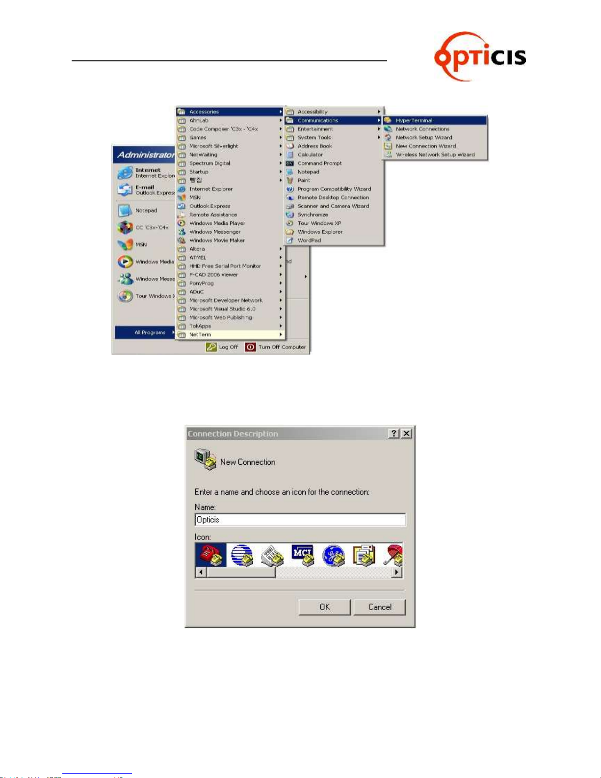
2) Select Start > Programs > Accessories > Communications > HyperTerminal
OHM-88 Manual Page 15
Page 16
USER MANUAL
HDMI MATRIX ROUTER : OHM-88
Figure 2-1 HyperTerminal Access
3) Connection Description Dialog: Enter a name and choose an icon.
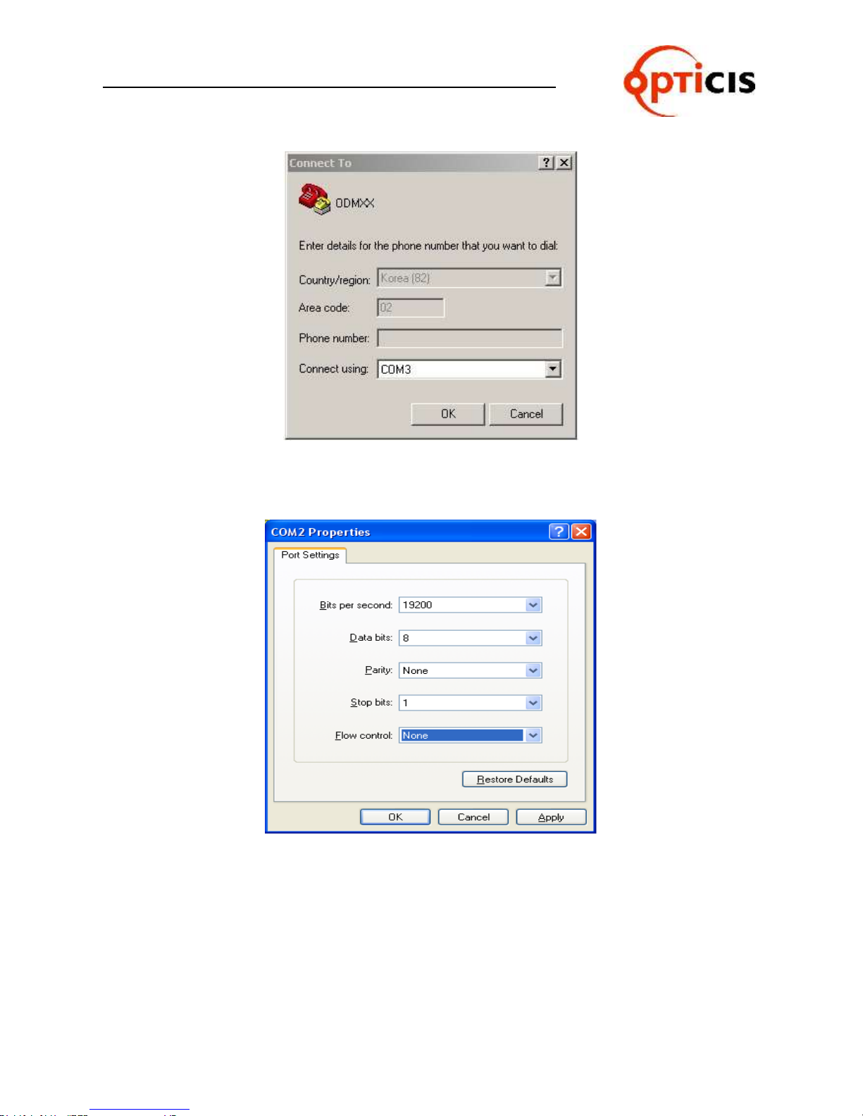
4) Selecting OK displays the Connect To dialog. In the Connect To dialog box,
ignore the Country, Area Code and Phone Number fields and select the
available COM port to which OHM-88 is connected.
OHM-88 Manual Page 16
Figure 2-2 Connection Description Dialog
Page 17
USER MANUAL
HDMI MATRIX ROUTER : OHM-88
Figure 2-3 Connect To Dialog
5) Select OK to go to the COM Properties dialog box.
Figure 2-4 COM Properties Dialog
6) Configure the port settings as follows;
OHM-88 Manual Page 17
Bits per second (baud rate): 19200 (recommended)
Data bits: 8
Parity: None
Stop bits: 1
Flow control: None
Page 18
USER MANUAL
HDMI MATRIX ROUTER : OHM-88
7) Select OK to display the HyperTerminal window
8) Press ENTER on OHM-88 to begin communication with OHM-88
9) Type serial command set. (Refer to Chap. 3.2)
2.7.2 Telnet
Telnet is a terminal emulation program for TCP/IP networks such as the Internet.
The Telnet program runs on your computer and connects your PC to a server on
the network. You can then enter commands through the Telnet program and they
will be executed as if you were entering them directly on the server console. This
enables you to control the server and communicate with other servers on the
network
2.7.3 Launching Telnet Session
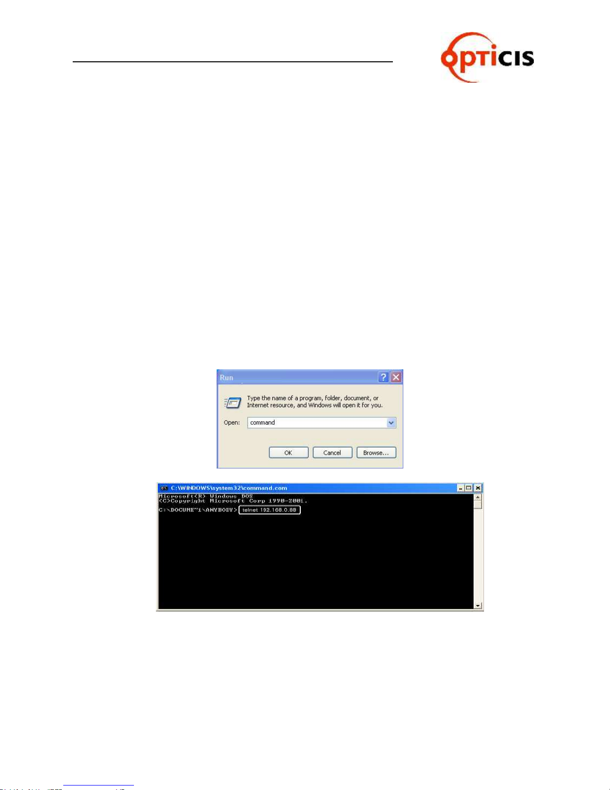
1) Select Start menu and select Run.
2) Type command as shown below.
Figure 2-5 Run Windows
OHM-88 Manual Page 18
Page 19
USER MANUAL
HDMI MATRIX ROUTER : OHM-88
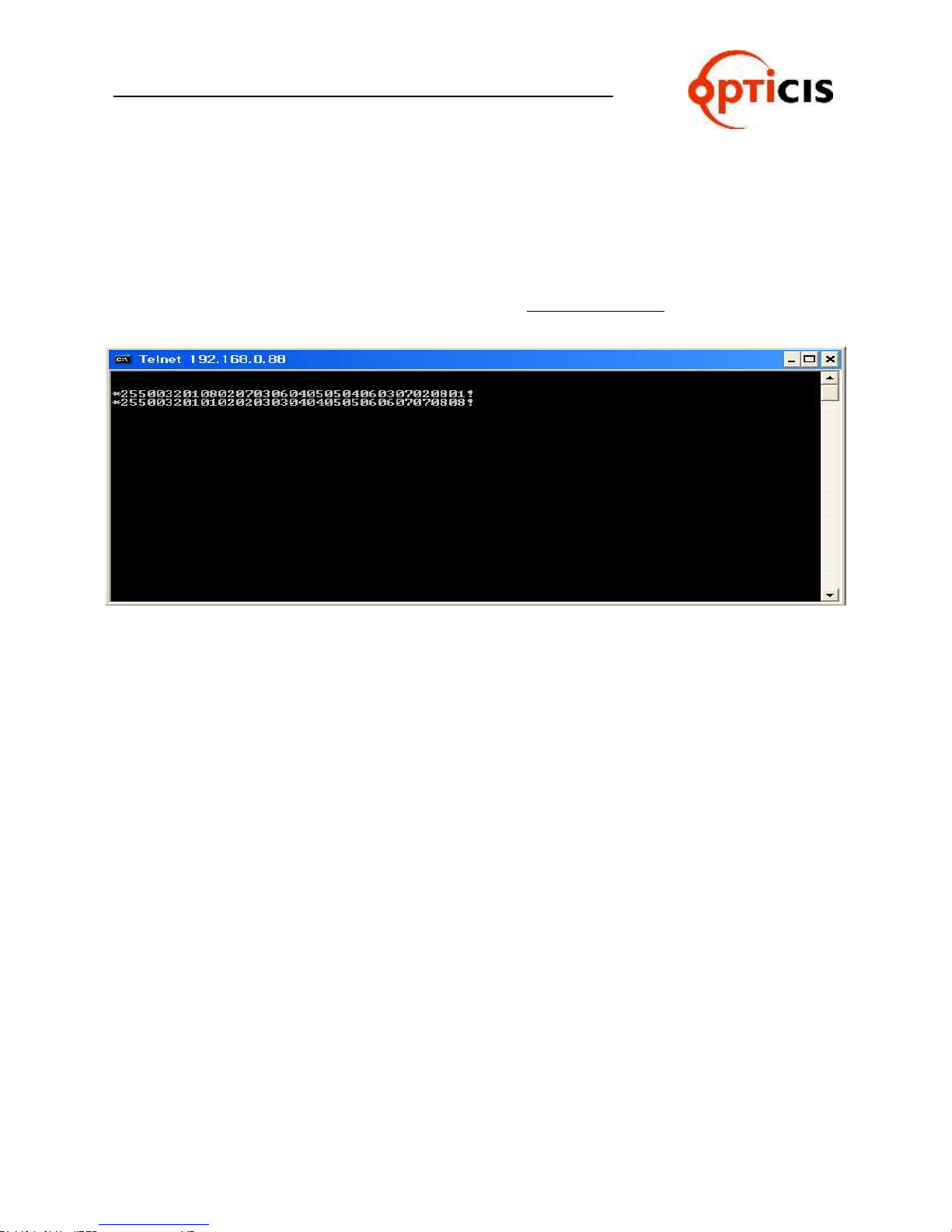
3) Select OK to open the command window.
4) Type the command: telnet 192.168.0.88
[Note] 192.168.0.88 is the default IP address of OHM88. Change IP address
as needed. (Refer to Chap. 2.6.6 and 2.8)
5) Press ENTER: “HDMI Matrix Router Connected” will be displayed.
6) Type serial command set. (Refer to Chap. 3.2)
Figure 2-6 Telnet connected
2.8 Ethernet Control
The OHM-88 can be controlled through the 10/100 base Ethernet port using either
graphic user interfaces or a command line interface.
The graphic user interfaces uses proprietary PC software.
The physical connection of OHM-88 can be made on the standard LAN or point to point
connection.
The command line interface uses a Telnet session to a private port.
To connect OHM-88 to Ethernet, specify a static IP address for OHM-88 (Refer to Chap.
2.6.6). The default IP address is 192.168.000.088.
2.8.1 SETTING THE IP ADDRESS of the PC
If the PC is connected to the OHM-88 through the 10/100 Base Ethernet port, a
static address should be configured on the PC:
1) Use Ethernet crossover cable (provided with OHM-88 system) for point
to point direct connection between PC or controller and OHM-88 or use
Ethernet strait cable to connect OHM-88 on LAN.
2) From the PC: select Start menu, select Control Panel.
3) In the Control Panel, select Network Connections.
In Network Connections, right click on Local Area Connection and select
Properties tab.
OHM-88 Manual Page 19
Page 20
USER MANUAL
HDMI MATRIX ROUTER : OHM-88
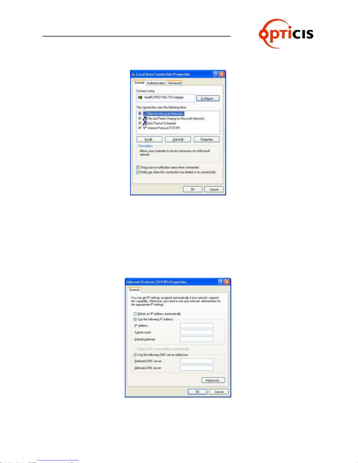
Figure 2-7 Local Area Network Properties
Select Internet Protocol (TCP/IP) and click on Properties. In the Internet Protocol (TCP/IP) Properties,
click Use the following IP address radio button. Enter IP address compatible with the current IP address
of the OHM-88.
For point to point direct connection, if the IP address of OHM-88 is
192.168.000.088, the PC IP address should be chosen as 192.168.000.nnn;
where nnn ranges 000 to 255 except 088. (Refer to Chap. 2.6.6)
For LAN connection, maintain existing PC IP address then consult you network
manager to obtain available IP address for OHM-88.
4) Select OK to terminate IP setup session.
OHM-88 Manual Page 20
Figure 2-8 PC IP address setting
Page 21

USER MANUAL
HDMI MATRIX ROUTER : OHM-88
3 Operation
OHM-88 has various operational interfaces: Front Panel Key Input, Serial Command Lines,
and Proprietary PC Software through RS-232, Ethernet.
Proprietary PC Software is the most efficient since all other methods use command line in-
terface.
3.1 Front Panel Operation
Please Refer to Chap. 2.2 for detail explanation of front keys functions.
Front Panel Operation examples:
8 Displays with 3 different typed of EDID:
Port No. Input Output
1 Source 1 Display 1 (EDID type A)
2 Source 2 Display 2 (EDID type B)
3 Source 3 Display 3 (EDID type B)
4 Source 4 Display 4 (EDID type A)
5 Source 5 Display 5 (EDID type B)
6 Source 6 Display 6 (EDID type C)
7 Source 7 Display 7 (EDID type C)
8 Source 8 Display 8 (EDID type A)
The arrows represent :
Input 1 to Output 1 and 4
Input 2 to Output 2
Input 3 to Output 3
Input 4 to Output 5
Input 5 no connection
Input 6 to Outputs 6 and 7
Input 7 to Output 8
Input 8 no connection
Operation is executed in two steps:
Set EDID for each Input port for proper graphic signal transmittal.
Configure Input-Output for cross-switching as configured above.
OHM-88 Manual Page 21
Page 22

USER MANUAL
HDMI MATRIX ROUTER : OHM-88
1) Press FUNCTION key – LCD will display EDID Read/Write:
=========Function Mode========
EDID Read/Write
IN : 1.2.3.4.5.6.7.8
OUT: 1.2.3.4.5.6.7.8
2) Configure as shown below:
=========Function Mode========
EDID Read/Write
IN : 1.2.3.4.5.6.7.8
OUT: 1.2.3.4.5.6.7.8
[Note] If a source is connected to two or more different displays, assigning the lower
resolution EDID to Input port EEPROM is highly recommended. Assigning higher
resolution will show ‘OUT OF RANGE’.
3) Press ENTER to save.
[Note] EDID setting is valid until a new EDID setting is processed - even though the
OHM-88 is powered on and off repeatedly.
4) To configure Input-Output, press CREATE; current Input-Output configuration will
be displayed.
========= Create Mode ========
I: 1 2 3 4 5 6 7 8 N
O: 1 2 3 4 5 6 7 8 M
Where N is Not defined for the monitoring, M.
5) Press Input button 1 (Green LED is on) – LCD displays:
========= Create Mode ========
Input Channel NUM.: 1
Out: 1
New:
Press Output 1 and 4 (number 1 and 4) as the selected outputs for the given Input.
Press ENTER key and then turn back to the user mode.
[Note] Specific Input can be connected to multiple Output channels. However, one Output
channel cannot share multiple Input channels.
Repeat above process 4 to 5 for other Input channels.
Press PREVIEW key to review newly saved Input-Output configuration;
========= Preview Mode ========
I: 1 2 3 4 5 6 7 8 N
O: 1 2 3 4 5 6 7 8 M
[Note] Pressing ENTER key completes the Input-Output configuration.
OHM-88 Manual Page 22
Page 23

USER MANUAL
Command Format
ASCII
HEX
Description
Byte
Start
*
0x2A
Header Code
1
Router ID
Variable
Variable
Router ID Value
3
Create
0
0x30
Connect or Disconnect the Selected
Input and Output channels
1
Preview
1
0x31
Preview all connected channels
1
Cancel
2
0X32
Cancel selected channel connection
1
Upload Data Request
3
0x33
Upload connection information to the
controller
1
Rolling
4
0x34
Rotates Input and Output connection
1
Upload Router ID
5
0x35
Upload Router ID to controller
1
Rolling Stop
6
0x36
Stop rolling command
1
Check Connection
7
0x37
Upload connection integrity
1
Upload One Channel Data
Request
8
0x38
Uploads the connection status of
selected channel
1
Baud Rate Setting
@
0x40
Change Baud rate of RS-232
1
Read Output Device EDID
A
0x41
Read EDID from attached display
1
Default EDID Setting
B
0x42
Restore factory default EDID on
EEPROM
1
HDMI MATRIX ROUTER : OHM-88
3.2 Command Line Operation
Command line interface is performed through RS-232 or Ethernet.
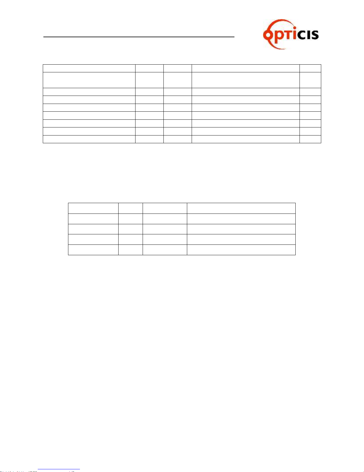
The commands are coded in ASCII and HEXA. All descriptions are shown in Table 3.1. A
command line consists of string of ASCII or HEXA codes in series as shown below;
Start (1 Byte) + Router ID (3 Bytes) + Command (1 Byte)
+ Data Length (3 Bytes)
+ Output Number (2 Bytes) + Input Number (2 Bytes)
+ Output Number (2 Bytes) + Input Number (2 Bytes) + …..
+ End (1 Byte)
A command line allows execution of only one command. Multiple commands require ex-
ecution of multiple strings; one command per string.
All strings begin with Start byte.
Router ID can be selected within the range of 000 to 255; written in 3 bytes. (Default
factory setting is 255. Refer to Chap. 2.1.)
Data Length represents total number of all bytes. Data Length is determined by the
number of channels in the command line.
For example: Configuring 4 Input-Output connections (8 channels), data
length is 016 in ASCII - 16 bytes in base of 2 bytes per channel regardless of
Input and Output.
Input channel Number follows Output channel Number - designated as a pair.
A command line closes with End byte.
Table 3.1 Descriptions of Command Codes
OHM-88 Manual Page 23
Page 24
USER MANUAL
Read Input EEPROM
C
0x43
Read EDID from EEPROM
1
EDID Write
D
0x44
Read EDID from display and write to
EEPROM
1
Edit EDID Write
E
0x45
Edit EDID Write mode
1
EDID Data
F
0x46
Send divided data by two
1
Monitoring
G
0x47
Set the monitoring channel
1
Data Length
Variable
3
Output channel
Variable
Selected Output channel
2
Input channel
Variable
Selected Input channel
2
End
!
0x21
Tail Code
1
Acronym
Bytes
HEX Codes
Description
Error
1
0x05
Router received incorrect data packet
RX Complete
1
0x06
Router received correct data packet
Job Complete
1
0x07
Completed operation per command
Connection OK
1
0xA0
Successful connection
HDMI MATRIX ROUTER : OHM-88
In response to the command line Input to OHM-88, the following ACK signals are re-
turned to the controller shown in Table 3.2.
Table 3.2 Descriptions of Acknowledge (ACK) Signals
ACK will be returned after command codes are sent.
If the command codes are successfully done, 0x06, 0x07 will be returned. But if it is failed,
0x05 will follow it by return. Some command codes have special ACK and it is described
under the each example command code below.
The followings illustrate example codes for various applications to be utilized on HyperTerminal
for RS-232 and on Telnet for TCP/IP.
OHM-88 Manual Page 24
Page 25

USER MANUAL
Start
Router ID
Command
Data Length
Output
Channel
Input
Channel
End
ASCII
* 2 5 5 0
0 0 4 0 1 0 1 ! HEX
2Ah
32h
35h
35h
30h
30h
30h
34h
30h
31h
30h
31h
21h
Start
Router ID
Command
Data Length
Output
Channel
Input
Channel
End
ASCII
* 2 5 5 0
0 0 4 0 1 0 0
!
HEX
2Ah
32h
35h
35h
30h
30h
30h
34h
30h
31h
30h
30h
21h
Start
Router ID
Command
Data Length
Output
Channel
Input Channel
ASCII
* 2 5 5 0
0 0 8 0 1 0 8
HEX
2Ah
32h
35h
35h
30h
30h
30h
38h
30h
31h
30h
38h
Output Channel
Input Channel
End 0 8 0 1 ! 30h
38h
30h
31h
21h
HDMI MATRIX ROUTER : OHM-88
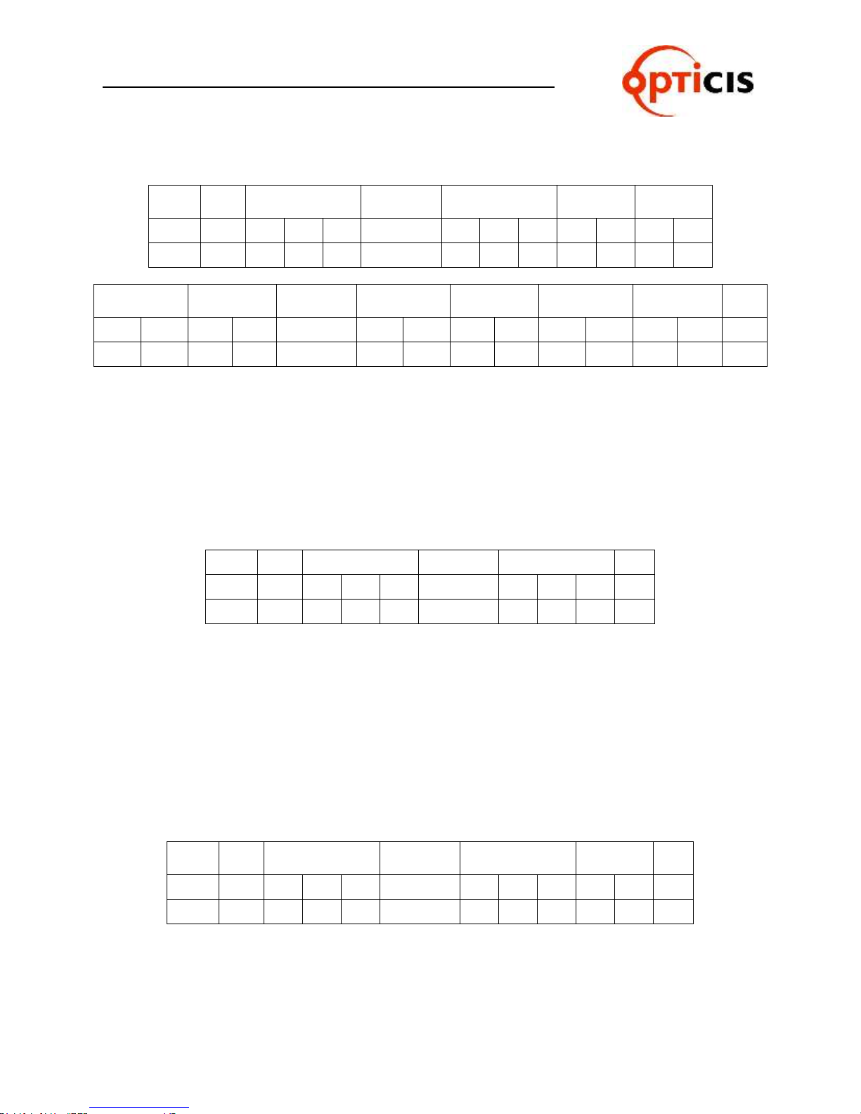
3.2.1 Create:
Configure cross-switching of inputs and outputs.
Command line format:
Start (*) + Router ID (3 byte) + Command (0) + Data Length (Variable) +
Output channel (2 byte) + Input channel (2 byte) + … + End (!)
ACK Return Signal:
RX Complete 0x06(06h), TX Complete 0x07(07h)
Example 1: One (1) channel connection of Output Channel 1 and Input Channel 1
Example 2: One (1) channel disconnection of Output Channel 1 by setting “0” on the Input channel
bytes.
Example 3: Two (2) channel connection: Output Channel 1 Input Channel 8 & Output Channel 8
Input Channel 1
OHM-88 Manual Page 25
Page 26
USER MANUAL
Start
Router ID
Command
Data Length
Output
Channel
Input
Channel
ASCII
* 2 5 5 0
0 3 2 0 1 0 1
HEX
2Ah
32h
35h
35h
30h
30h
33h
32h
30h
31h
30h
31h
Output
Channel
Input
Channel
…
Output
Channel
Input
Channel
Output
Channel
Input
Channel
END
0 2 0 2 ...
0 7 0 7 0 8 0 8 !
30h
32h
30h
32h … 30h
37h
30h
37h
30h
38h
30h
38h
21h
Byte
Start
Router ID
Command
Data Length
Input
Channel
End
ASCII
* 2 5 5 2
0 0 2 0 1 ! Hex
2Ah
32h
35h
35h
32h
30h
30h
32h
30h
31h
21h
Byte
Start
Router ID
Command
Data Length
End
ASCII
* 2 5 5 1
0 0 0 ! Hex
2Ah
32h
35h
35h
31h
30h
30h
30h
21h
HDMI MATRIX ROUTER : OHM-88
Example 4: Eight (8) channel direct - through connection (for ODM-88)
3.2.2 Preview: Shows all Input-Output configurations
Command line format:
Start (*) + Router ID (3 byte) + Command (1) + Data Length (000) + End (!)
ACK Return Signal:
RX Complete 0x06(06h), TX Complete 0x07(07h)
3.2.3 Cancel: Cancels configuration of outputs for each Input.
Command line format:
Start (*) + Router ID (3 byte) + Command (2) + Data Length (variable) + Input
Channel (2 byte) + End (!)
ACK Return Signal:
RX Complete 0x06(06h), TX Complete 0x07(07h)
Example: Disconnect Input Channel 1
OHM-88 Manual Page 26
Page 27
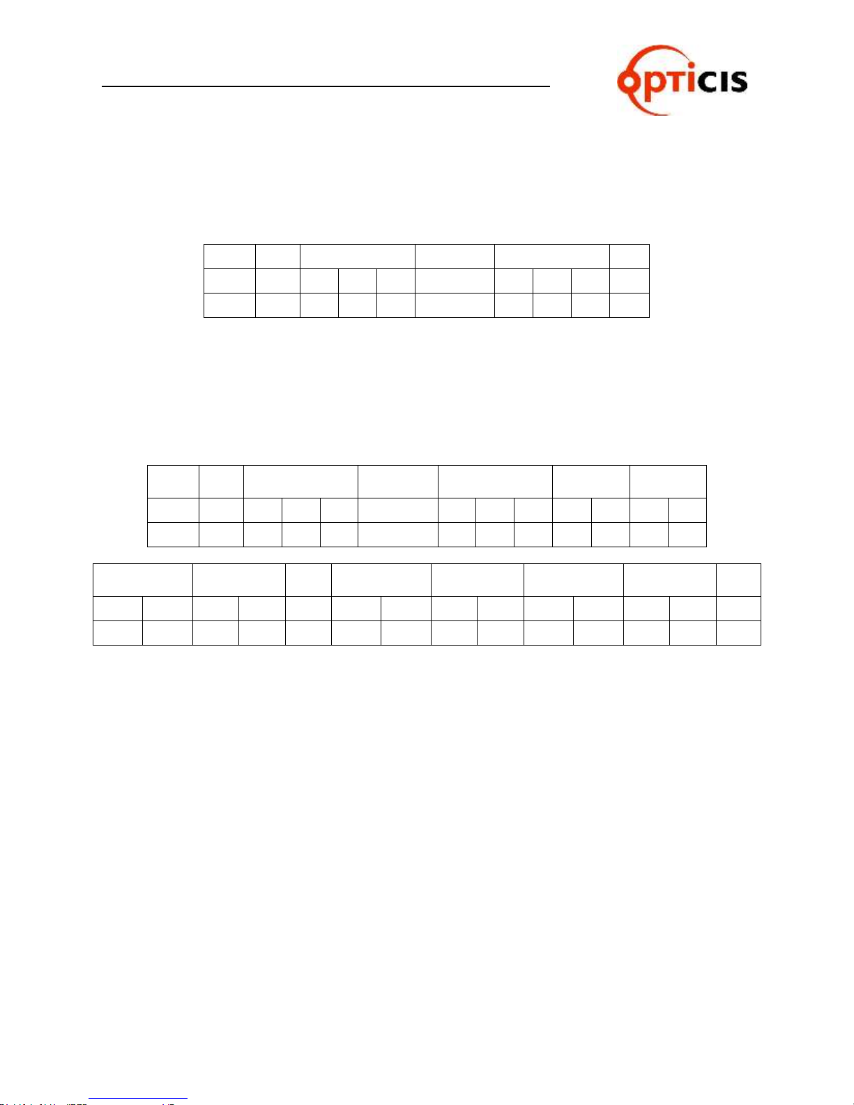
USER MANUAL
Byte
Start
Router ID
Command
Data Length
Output
Channel
Input
Channel
ASCII
* 2 5 5 3
0 3 2 0 1 0 1
Hex
2Ah
32h
35h
35h
33h
30h
33h
32h
30h
31h
30h
31h
Output
Channel
Input
Channel
…
Output
Channel
Input
Channel
Output
Channel
Input
Channel
END
0 2 0 2 ........ 0 7 0 7 0 8 0 8 ! 30h
32h
30h
32h
……
30h
37h
30h
37h
30h
38h
30h
38h
21h
Byte
Start
Router ID
Command
Data Length
End
ASCII
* 2 5 5 3
0 0 0 ! Hex
2Ah
32h
35h
35h
33h
30h
30h
30h
21h
HDMI MATRIX ROUTER : OHM-88
3.2.4 Upload Data Request: Uploads connection data to the controller.
Command line format:
Start (*) + Router ID (3 byte) + Command (3) + Data Length (000) + End (!)
Allows OHM-88 to respond with ACK signal to controller in the following format:
0x06(06h) + Connection DATA + 0x07(07h)
The Connection Data represents the connection information of router
* Connection Data for OHM-88: 1-1, 2-2, 3-3, 4-4, 5-5, 6-6, 7-7, 8-8
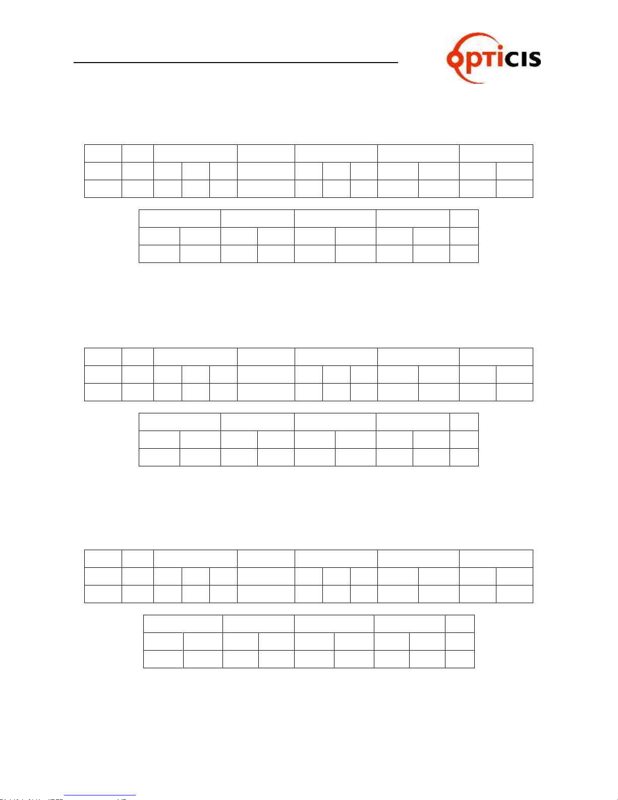
3.2.5 Rolling command
Rotates Input at fixed Output.
Checks connection status of all inputs and outputs by changing them in se-
quence.
Format of Command Line:
Start (*) + Router ID (3 byte) + Command (4) + Data Length (Variable) +
Output Channel (2 byte) + Input Channel (2 byte) + … + End (!)
Example: To rotate three(3) inputs1, 2, and 3 on three (3) outputs 1, 2, and 3.
ACK Return Signal:
RX Complete 0x06(06h), TX Complete 0x07(07h)
OHM-88 Manual Page 27
Page 28
USER MANUAL
Byte
Start
Router ID
Command
Data Length
Output Channel
Input Channel
ASCII
* 2 5 5 4
0 1 2 0 1 0 1
Hex
2Ah
32h
35h
35h
34h
30h
31h
32h
30h
31h
30h
31h
Output Channel
Input Channel
Output Channel
Input Channel
End 0 2 0 2 0 3 0 3 ! 30h
32h
30h
32h
30h
33h
30h
33h
21h
Byte
Start
Router ID
Command
Data Length
Output Channel
Input Channel
ASCII
* 2 5 5 4
0 1 2 0 1 0 2
Hex
2Ah
32h
35h
35h
34h
30h
31h
32h
30h
31h
30h
32h
Output Channel
Input Channel
Output Channel
Input Channel
End 0 2 0 3 0 3 0 1 ! 30h
32h
30h
33h
30h
33h
30h
31h
21h
Byte
Start
Router ID
Command
Data Length
Output Channel
Input Channel
ASCII
* 2 5 5 4
0 1 2 0 1 0 3
Hex
2Ah
32h
35h
35h
34h
30h
31h
32h
30h
31h
30h
33h
Output channel
Input channel
Output channel
Input channel
End 0 2 0 1 0 3 0 2 ! 30h
32h
30h
31h
30h
33h
30h
32h
21h
HDMI MATRIX ROUTER : OHM-88
1) Output Channel 1 Input Channel 1, Output Channel 2 Input Channel 2, Output Channel 3 Input
Channel 3
2) Output Channel 1 Input Channel 2, Output Channel 2 Input Channel 3, Output Channel 3 Input
Channel 1
3) Output Channel 1 Input Channel 3, Output Channel 2 Input Channel 1, Output Channel 3 Input
Channel 2
OHM-88 Manual Page 28
Page 29
USER MANUAL
Byte
Start
Router ID
Command
Data Length
End
ASCII
* 2 5 5 5
0 0 0
!
Hex
2Ah
32h
35h
35h
35h
30h
30h
30h
21h
Byte
Start
Router ID
Command
Data Length
End
ASCII
* 0 1 5 5
0 0 0
!
Hex
2Ah
30h
31h
35h
35h
30h
30h
30h
21h
Byte
Start
Router ID
Command
Data Length
End
ASCII
* 2 5 5 6
0 0 0 ! Hex
2Ah
32h
35h
35h
36h
30h
30h
30h
21h
Byte
Start
Router ID
Command
Data Length
End
ASCII
* 2 5 5 7
0 0 0 ! Hex
2Ah
32h
35h
35h
37h
30h
30h
30h
21h
HDMI MATRIX ROUTER : OHM-88
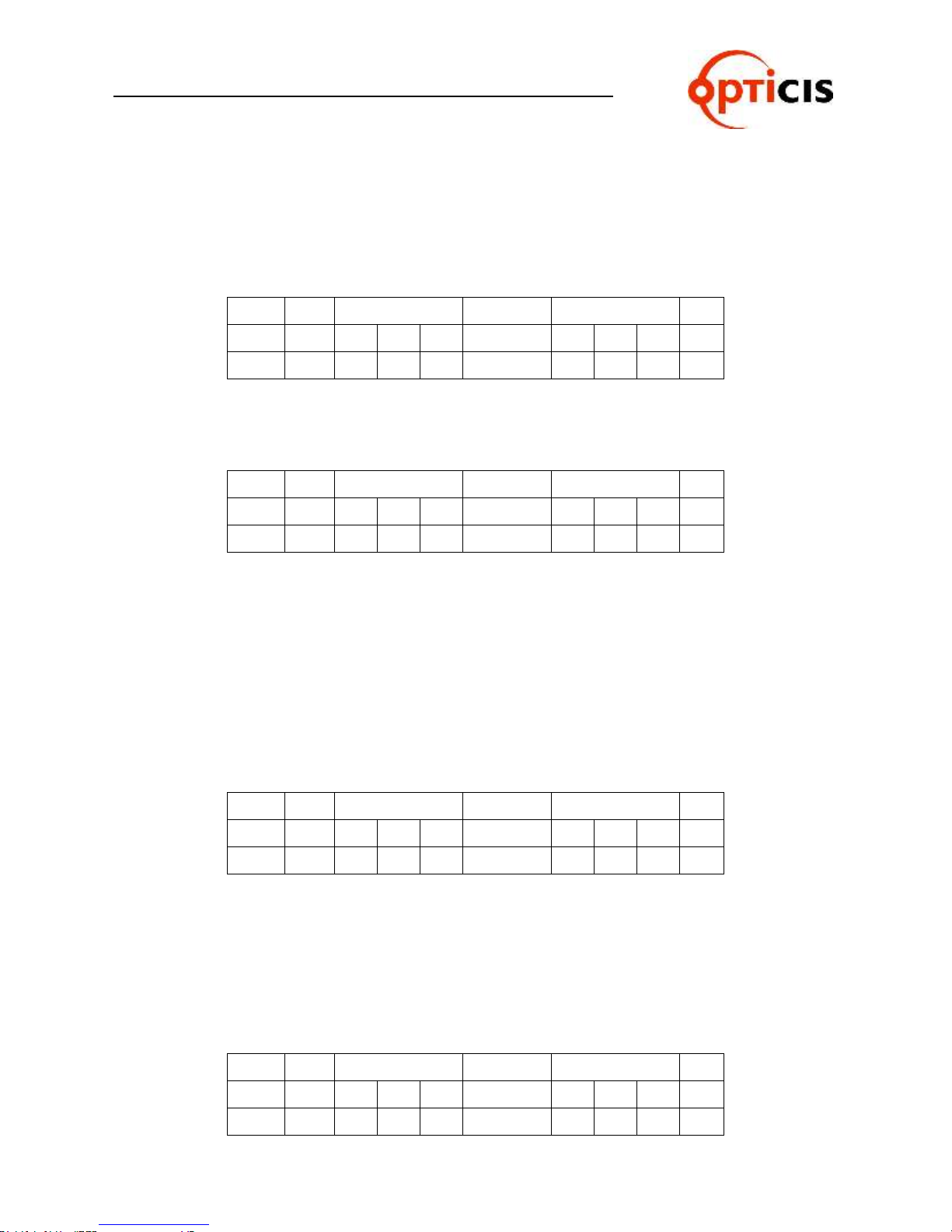
3.2.6 Upload Router ID
Uploads Router ID to the controller or PC.
Command line format:
Start (*) + Router ID (3 byte) + Command (5) + Data Length (000) + End (!)
Allows OHM-88 to respond with ACK signal to controller in the following format:
0x06(06h) + Connection DATA + 0x07(07h)
If the Router ID is 015, ACK signal is as follows:
Connection DATA
3.2.7 Rolling Stop
Rolling stop command.
Command line format:
Start (*) + Router ID (3 byte) + Command (6) + Data Length (000) + End (!)
ACK Return Signal:
RX Complete 0x06(06h), TX Complete 0x07(07h)
3.2.8 Check Connection
Check status of all connections
Command line format:
Start (*) + Router ID (3 byte) + Command (7) + Data Length (000) + End (!)
OHM-88 Manual Page 29
Page 30

USER MANUAL
Byte
Start
Router ID
Command
Data Length
Output channel
End
ASCII
* 2 5 5 8
0 0 2 0 1 ! Hex
2Ah
32h
35h
35h
38h
30h
30h
32h
30h
31h
21h
Byte
Start
Router ID
Command
Data Length
Input channel
End
ASCII
* 2 5 5 8
0 0 2 0 6 ! Hex
2Ah
32h
35h
35h
38h
30h
30h
32h
30h
36h
21h
Byte
Start
Router ID
Command
Data Length
Output Channel
End
ASCII
* 2 5 5 A
0 0 2 0 1
!
Hex
2Ah
32h
35h
35h
41h
30h
30h
32h
30h
31h
21h
HDMI MATRIX ROUTER : OHM-88
By sending Check Connection command to the router, OHM-88 responds with
the following ACK signal to controller :
Good connection: 0xA0 (A0h)
Bad connection: 0x05 (05h)
3.2.9 Upload One Channel Data Request
Upload connection status of a selected Output channel.
Command line format:
Start (*) + Router ID (3 byte) + Command (8) + Data Length (002) + Output
channel (2 byte) + End (!)
Allows OHM-88 to respond with ACK signal to controller in the following format:
0x06(06h) + Connection DATA + 0x07(07h)
Input 6 Output 1 connection
Connection DATA
3.2.10 Read Output Device EDID
Read EDID from connected display.
Command line format:
Start (*) + Router ID (3 byte) + Command (A) + Data Length (002) + Output
channel (2 byte) + End (!)
Allows OHM-88 to respond with ACK signal to controller in the following format:
0x06(06h) + Connection DATA + 0x07(07h)
Example: Read EDID from a Display connected to Output 1
OHM-88 Manual Page 30
Page 31

USER MANUAL
Byte
Start
ID
Command
Data Length
Output
Channel
EDID (256Byte)
End
ASCII
* 2 5 5 A
2 5 8 0 1 … !
Hex
2Ah
32h
35h
35h
41h
32h
35h
38h
30h
31h
00h…xxh
21h
Byte
Start
Router ID
Command
Data Length
Input EEPROM
End
ASCII
* 2 5 5 C
0 0 2 0 2
!
Hex
2Ah
32h
35h
35h
43h
30h
30h
32h
30h
32h
21h
Byte
Start
Router ID
Command
Data Length
Input
EEPROM
EDID
(256Byte)
End
ASCII
* 2 5 5 C
2 5 8 0 2 … !
Hex
2Ah
32h
35h
35h
43h
32h
35h
38h
30h
32h
00h…xxh
21h
HDMI MATRIX ROUTER : OHM-88
Connection DATA
EDID (256 Bytes) contains EDID information of Output display 1.
3.2.11 Read Input EEPROM EDID
Read EDID stored on EEPROM of an Input.
Format of Command Line:
Start (*) + Router ID (3 byte) + Command (C) + Data Length (002) + Input
EEPROM (2 byte) + End (!)
Allows OHM-88 to respond with ACK signal to controller in the following format:
0x06(06h) + Connection DATA + 0x07(07h)
Example: Read EDID stored on EEPROM of Input 2
EDID (256 Bytes) contains EDID information stored on EEPROM 2.
3.2.12 EDID Write
Read EDID information from connected displays and writes EDID to each
EEPROM.
Connection DATA
Format of Command Line:
Start (*) + Router ID (3 byte) + Command (D) + Data Length (Variable) +
EEPROM 1 (2 byte) + EEPROM 2 (2 byte) + … + End (!)
Variable in Data Length is determined by multiplying 2 bytes to the
OHM-88 Manual Page 31
maximum number of Input channels. With OHM-88, it is 16 bytes, multiplying 2 bytes by 8 inputs.
Page 32
USER MANUAL
Byte
Start
Router ID
Command
Data Length
EEPROM 1
EEPROM 2
ASCII
* 2 5 5 D
0 1 6 0 1 0 3
Hex
2Ah
32h
35h
35h
44h
30h
31h
36h
30h
31h
30h
33h
EEPROM 3
……..
EEPROM 8
END
0 0 … … 0 0 !
30h
30h … …
30h
30h
21h
Byte
Start
Router ID
Command
Data Length
End
ASCII
* 2 5 5 B
0 0 0
!
Hex
2Ah
32h
35h
35h
42h
30h
30h
30h
21h
HDMI MATRIX ROUTER : OHM-88
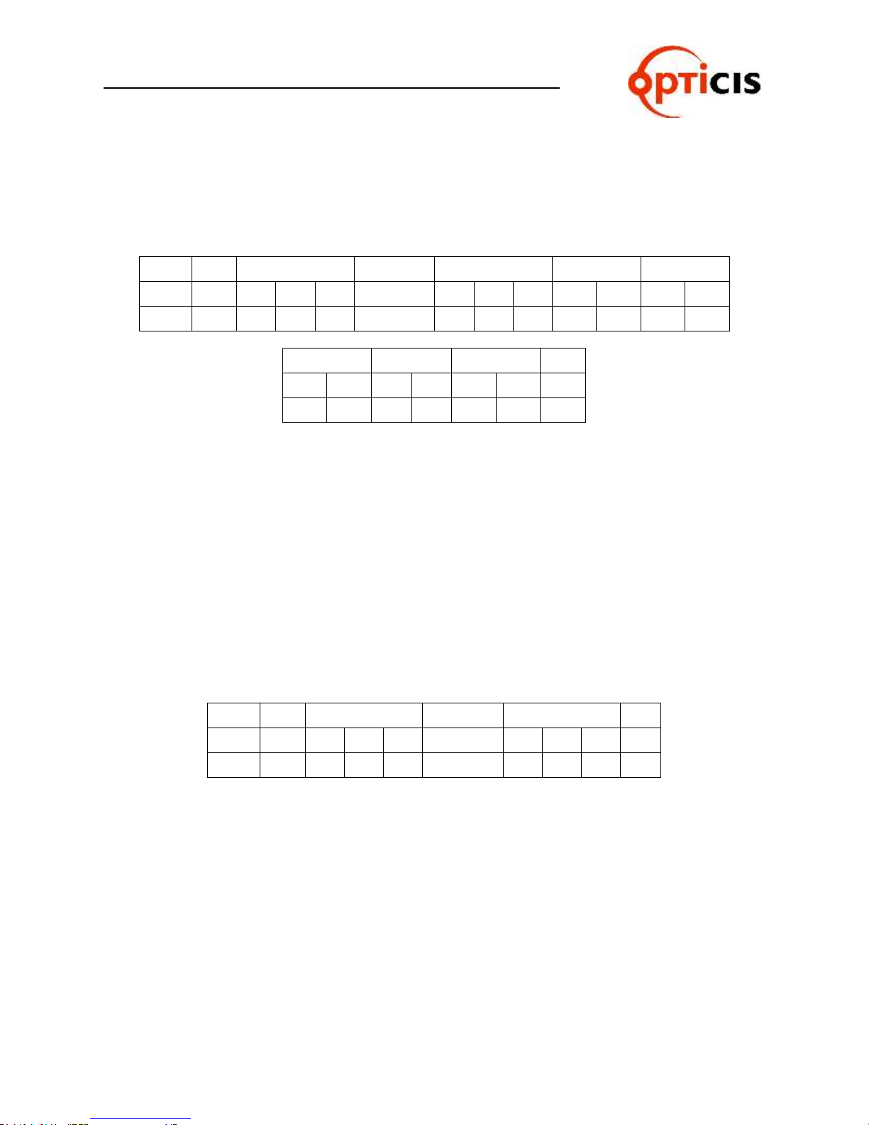
The 2 bytes in EEPROM # represents the Output port number of target
display. For example, 03 in EEPROM 2 represents: load the EDID of
Output 3 display into EEPROM 2. The value, 00 in EEPROM # represent: no updating to EEPROM.
Example: Sets, Output 1 display Input 1 EEPROM; Output 3 display Input 2 EEPROM)
ACK Return Signal:
RX Complete 0x06(06h), TX Complete 0x07(07h)
3.2.13 Default EDID Setting
Restores factory default EDID on EEPROM.
Command line format:
Start (*) + Router ID (3 byte) + Command (B) + Data Length (000) + End (!)
ACK Return Signal:
RX Complete 0x06(06h), TX Complete 0x07(07h)
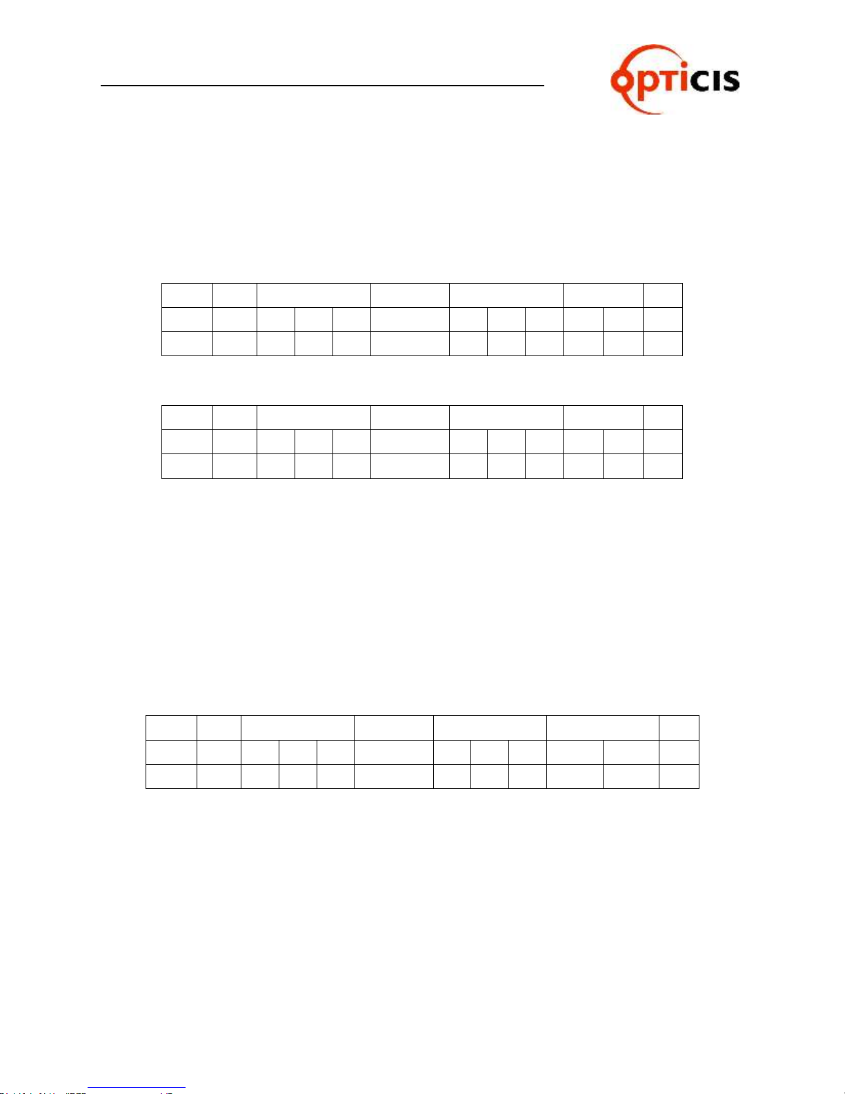
3.2.14 Baud rate Setting
Change baud rate through RS-232.
Command line format:
Start (*) + Router ID (3 byte) + Command (@) + Data Length (002) + Baud
Rate (variable) + End (!)
The default baud rate is 19,200
Baud rate options:
01 for 19,200bps
02 for 38,400bps
OHM-88 Manual Page 32
Page 33
USER MANUAL
Byte
Start
ID
Command
Data Length
Baud Rate
End
ASCII
* 2 5 5 @
0 0 2 0 2 ! Hex
2Ah
32h
35h
35h
40h
30h
30h
32h
30h
32h
21h
Byte
Start
ID
Command
Data Length
Baud Rate
End
ASCII
* 2 5 5 @
0 0 2 0 2 ! Hex
2Ah
32h
35h
35h
40h
30h
30h
32h
30h
32h
21h
Byte
Start
ID
Command
Data Length
Monitoring Data
End
ASCII
* 2 5 5 G
0 0 2 0 2 ! Hex
2Ah
32h
35h
35h
47h
30h
30h
32h
30h
32h
21h
HDMI MATRIX ROUTER : OHM-88
03 for 57,600bps
04 for 115,200bps
Allows OHM-88 to respond with ACK signal to controller in the following format:
0x06(06h) + Connection DATA + 0x07(07h)
Example: Set the baud rate to 38,400bps.
Connection DATA
3.2.15 Monitoring
Sets monitoring channel.
Format of Command Line:
Start (*) + Router ID (3 byte) + Command (G) + Data Length (002) + Moni-
toring Data (2 byte) + End (!)
ACK Return Signal:
RX Complete 0x06(06h), TX Complete 0x07(07h)
Ex.> Set Input Channel 2 as the Monitoring channel
OHM-88 Manual Page 33
Page 34
USER MANUAL
HDMI MATRIX ROUTER : OHM-88
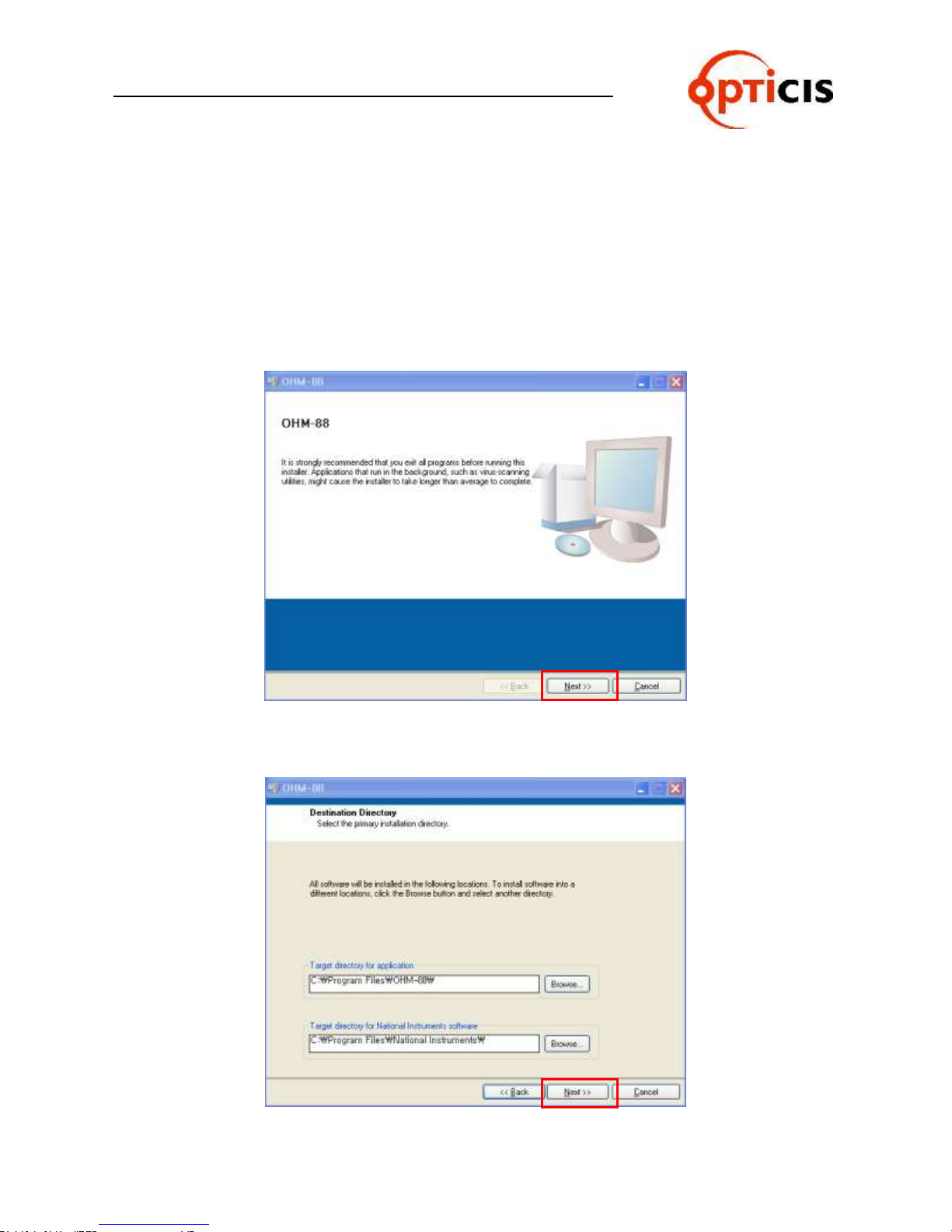
3.3 Proprietary PC Software Installation
3.3.1 Installation of PC Application
1) Insert OHM-88 software CD ROM into PC. If the CD ROM does not
automatically run, Select Start >Run. Enter X:\ ‘OHM-88 Setup.exe,
(where X is the letter of your CD ROM drive)
2) Installation of OHM-88 screen will be opened. Click on the Next button.
3) Select the destination directory path and click on the Next button.
OHM-88 Manual Page 34
Page 35
USER MANUAL
HDMI MATRIX ROUTER : OHM-88
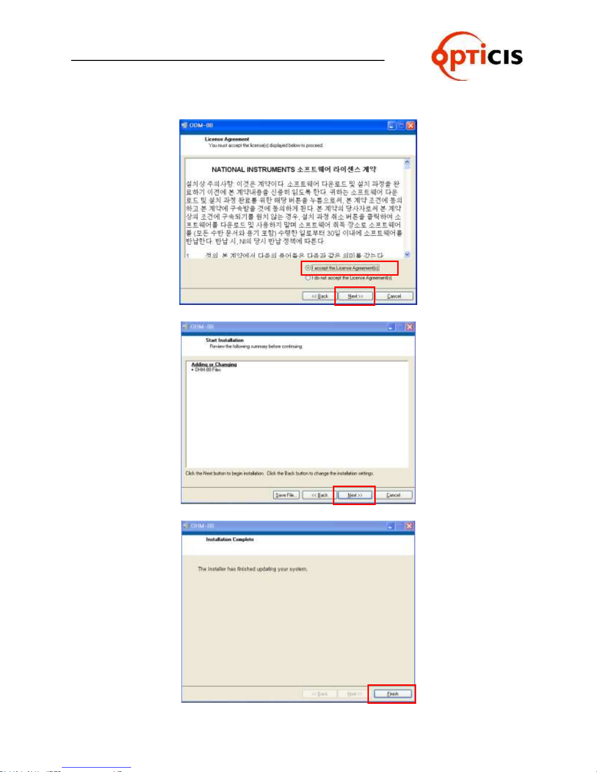
4) Select “I accept the License Agreement(s)” and click on the Next button.
5) Click on the Next button.
6) To complete the installation, click on the Finish button.
OHM-88 Manual Page 35
Page 36
USER MANUAL
HDMI MATRIX ROUTER : OHM-88
3.4 Proprietary PC Software Operation
3.4.1 PC Operation using RS-232
1) Connect RS-232 cable between OHM-88 and PC.
2) Turn on power switch.
3) Set Baud rate with reference to Function mode manual. (Refer to chap. 2.6.3)
- Default setting is 19200bps.
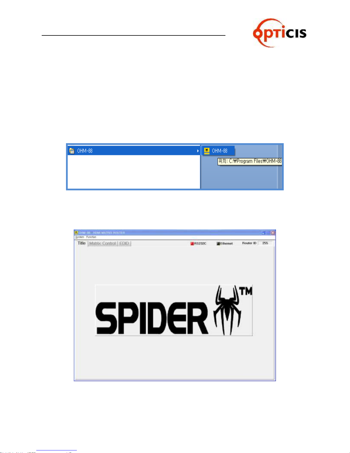
4) Execute PC operating software. (Select Start > Program > OHM-88)
5) Following will be displayed at first page (Title).
OHM-88 Manual Page 36
Page 37
USER MANUAL
HDMI MATRIX ROUTER : OHM-88
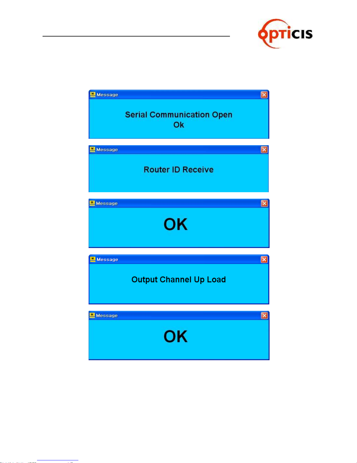
6) Following message will be opened step by step for serial communication,
router ID and output channel status.
OHM-88 Manual Page 37
Page 38
USER MANUAL
HDMI MATRIX ROUTER : OHM-88
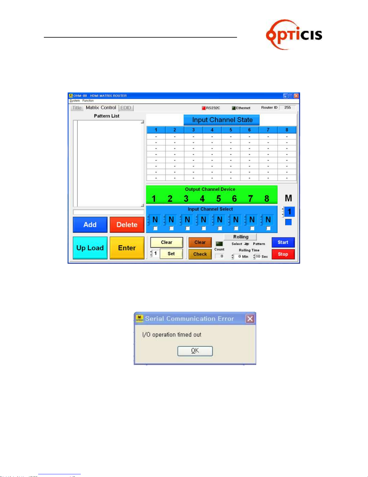
7) Following will be displayed if all connection and setting is in normal.
8) Error message will be opened if the connection and setting is not in normal.
ex) Following error message will be opened when cable connection and baud rate
setting is not in normal.
OHM-88 Manual Page 38
Page 39
USER MANUAL
HDMI MATRIX ROUTER : OHM-88
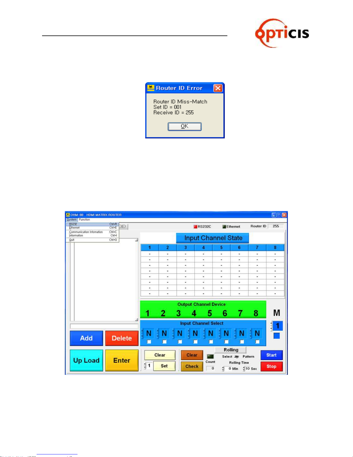
ex) Following error message will be opened when Router ID is not set in normal.
Set ID = PC Software
Receive ID = OHM-88 MATRIX ROUTER
[Note] Set ID and Receive ID should be same.
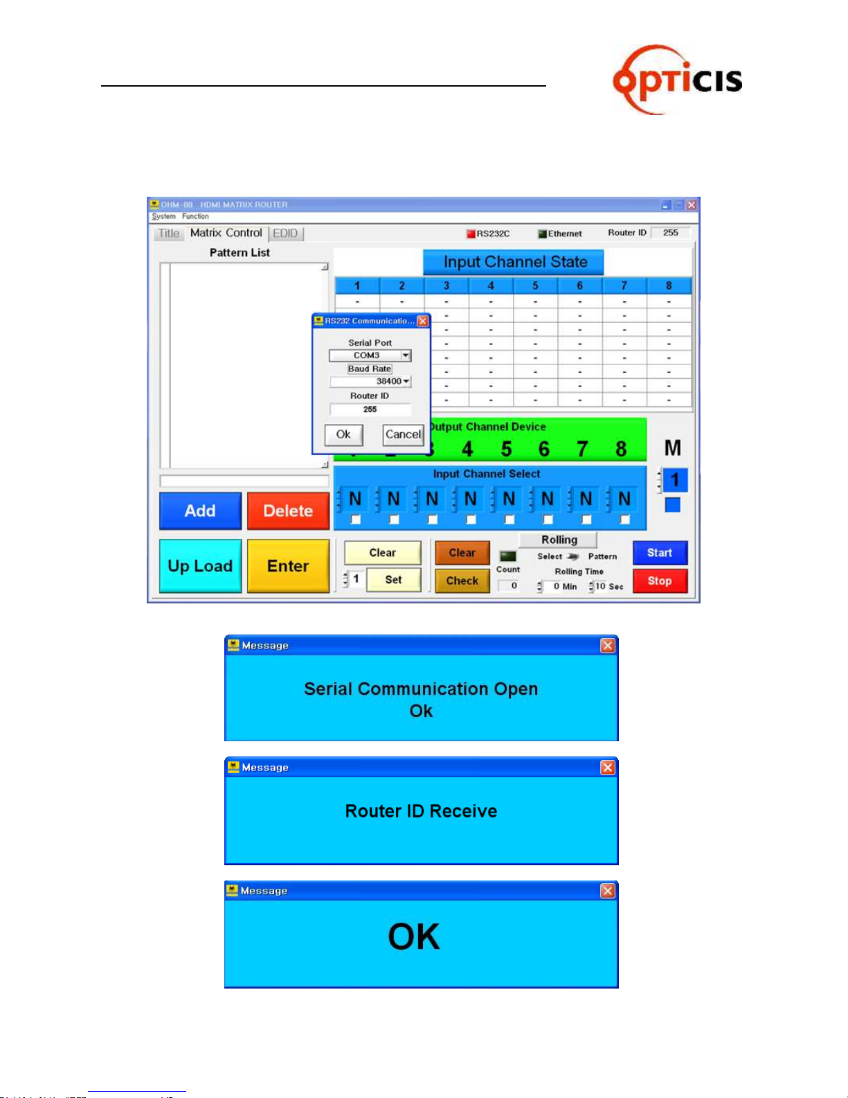
9) Setting for Serial Port, Baud Rate and Router ID
Select System > RS232 at the menu bar.
OHM-88 Manual Page 39
Page 40
USER MANUAL
HDMI MATRIX ROUTER : OHM-88
10) Click on the OK button after setting desired data.
OHM-88 Manual Page 40
Page 41
USER MANUAL
HDMI MATRIX ROUTER : OHM-88
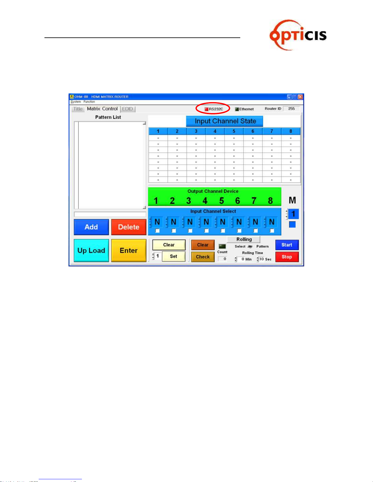
11) RS232C check box color will be changed to red color if all process is in normal.
OHM-88 Manual Page 41
Page 42
USER MANUAL
HDMI MATRIX ROUTER : OHM-88
3.4.2 PC Operation using Ethernet
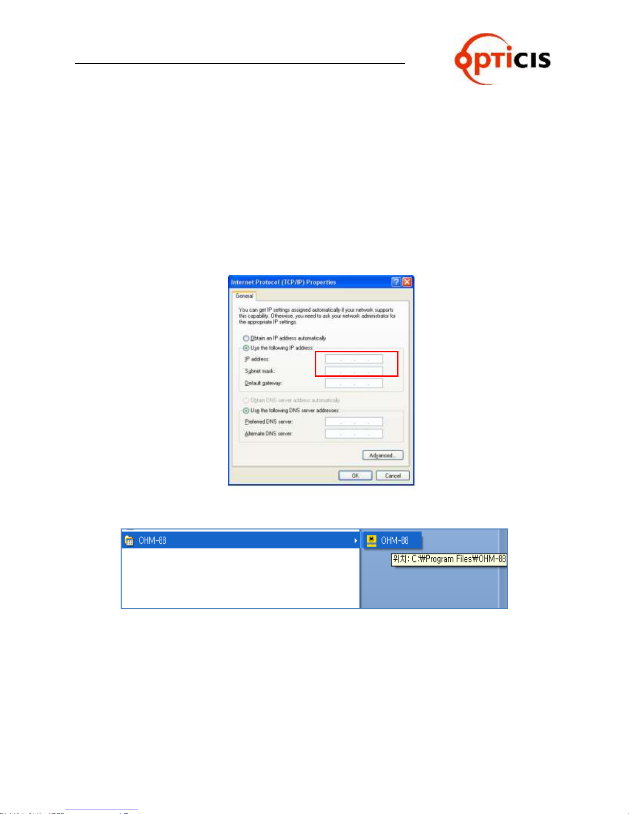
1) Connect Ethernet cable between OHM-88 and PC.
Caution) Crossover cable should be used for point to point connection and direct
cable should be used for LAN connection. Shipping cable as an accessory is
crossover cable.
2) Turn on power switch.
3) Set the Gate Way, Subnet Mask, IP Address with reference to Function mode
manual. (Refer to chap. 2.6.4 ~ 2.6.6)
For point to point direct connection, if the IP address of ODM-88 is
192.168.000.088, the PC IP address should be chosen as 192.168.000.nnn;
where nnn ranges 000 to 255 except 088. (Refer to Chap. 2.8.1)
4) Execute PC operating software.(Select Start > Program > OHM-88)
OHM-88 Manual Page 42
Page 43
USER MANUAL
HDMI MATRIX ROUTER : OHM-88
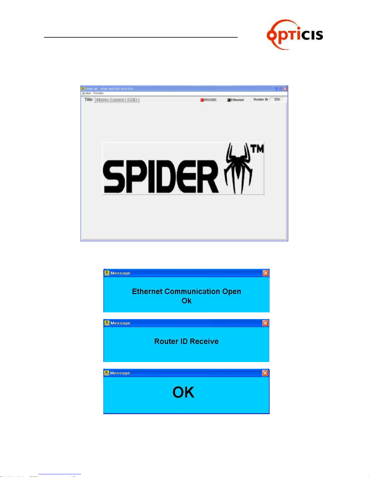
5) Following will be displayed at first page (Title).
6) Following message will be opened step by step for Ethernet communication,
router ID and output channel status.
OHM-88 Manual Page 43
Page 44
USER MANUAL
HDMI MATRIX ROUTER : OHM-88
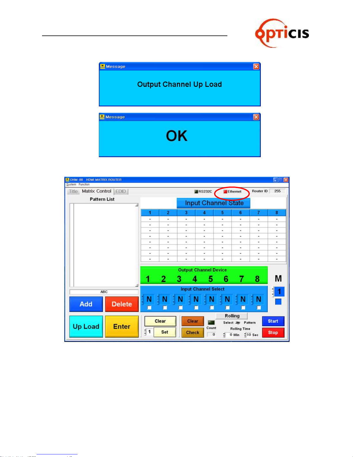
7) Following will be displayed if all connection and setting is in normal.
OHM-88 Manual Page 44
Page 45
USER MANUAL
HDMI MATRIX ROUTER : OHM-88
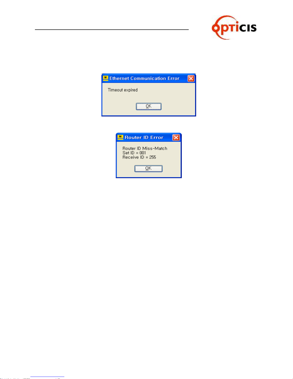
8) Error message will be opened if the connection and setting is not in normal.
ex) Following error message will be opened when Ethernet setting is not in normal.
ex) Following error message will be opened when Router ID is not set in normal.
Set ID = PC Software
Receive ID = OHM-88 MATRIX ROUTER
[Note] Set ID and Receive ID should be same.
OHM-88 Manual Page 45
Page 46
USER MANUAL
HDMI MATRIX ROUTER : OHM-88
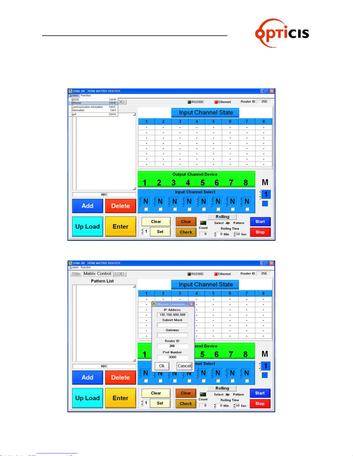
9) Set the Ethernet communication and Router ID
[Note] Both IP address of OHM-88 and PC should be same.
Select System > Ethernet at the menu bar
10) Click on the OK button after setting desired data.
OHM-88 Manual Page 46
Page 47
USER MANUAL
HDMI MATRIX ROUTER : OHM-88
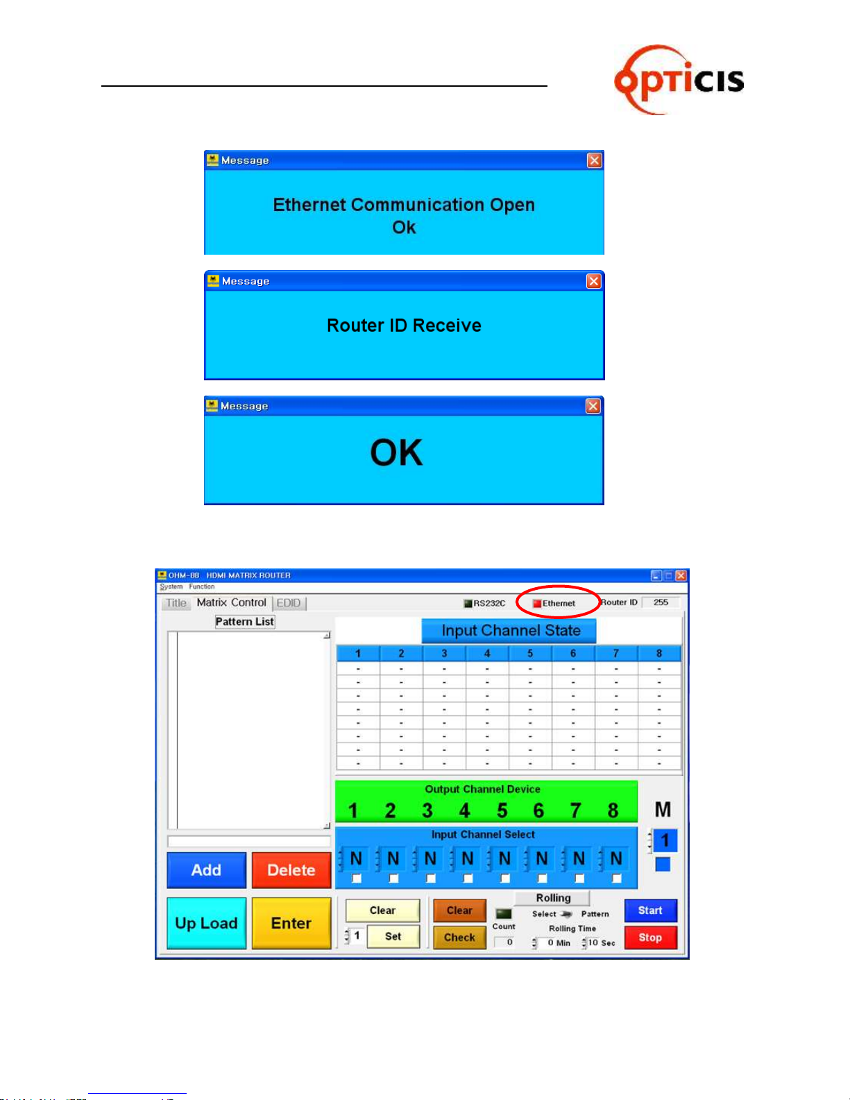
11) Ethernet check box color will be changed to red color if all process is in normal.
OHM-88 Manual Page 47
Page 48
USER MANUAL
HDMI MATRIX ROUTER : OHM-88
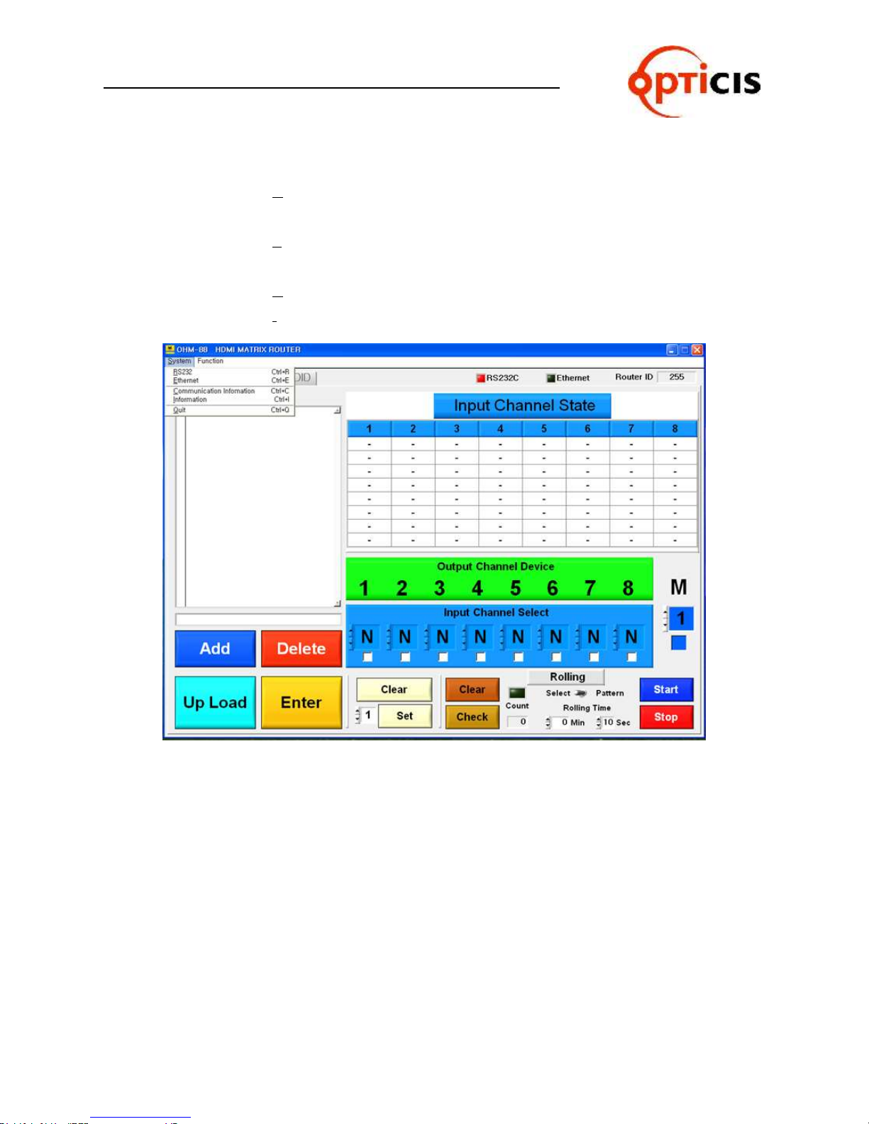
3.4.3 System menu
RS232: Set the Serial Port, Baud Rate, Router ID for
RS232 communication.
Ethernet: Set the IP Address, Subnet Mask, Gateway, Router ID and
Port number for Ethernet communication.
Communication Information: Information for Tx and Rx communication.
Information: Information for PC software version.
OHM-88 Manual Page 48
Page 49
USER MANUAL
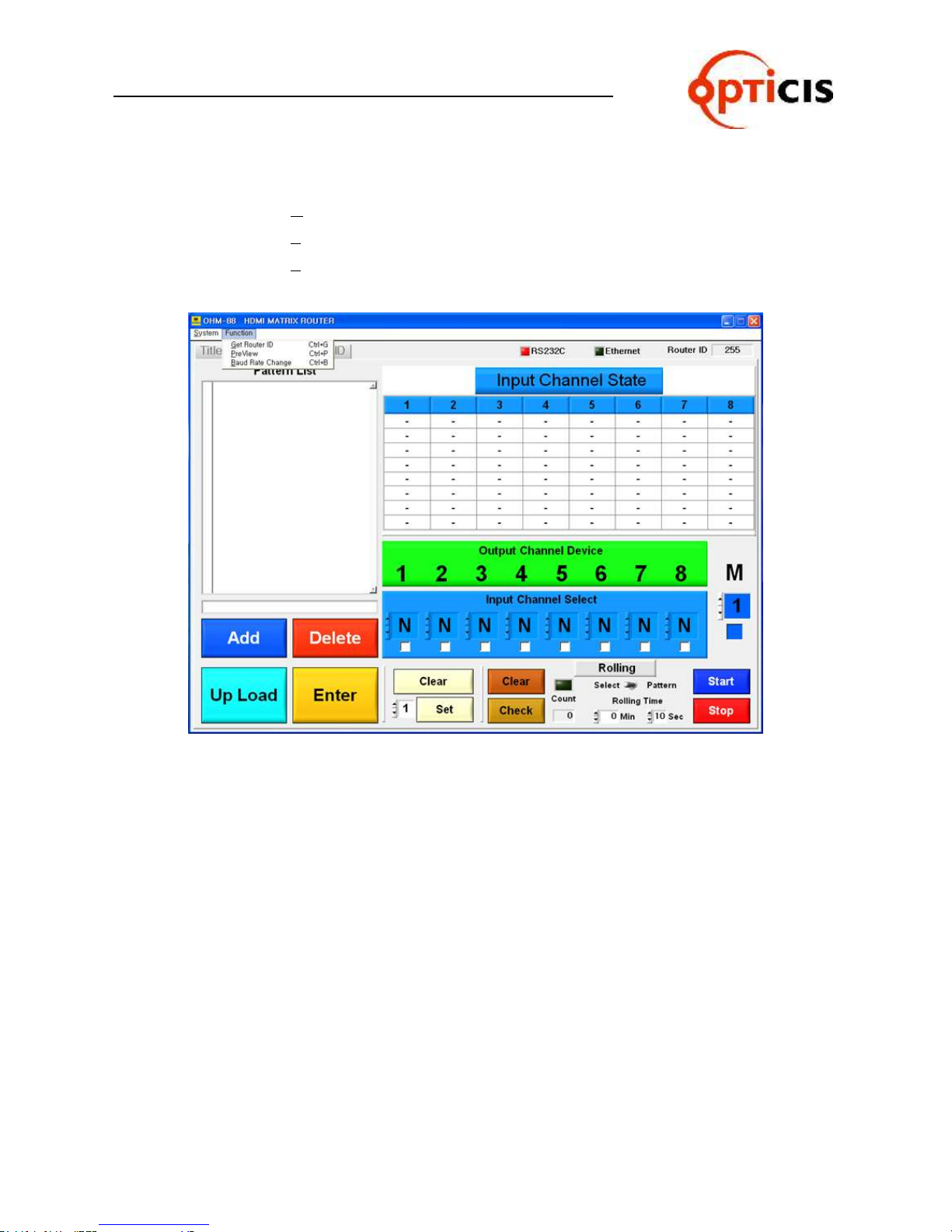
HDMI MATRIX ROUTER : OHM-88
3.4.4 Function menu
Get Router ID: Match PC Software with Router ID after reading Router ID
PreView: Verifies current Input-Output connection status.
Baud Rate Change: Change Baud Rate at PC Software
OHM-88 Manual Page 49
Page 50

USER MANUAL
HDMI MATRIX ROUTER : OHM-88
3.4.5 Title Folder – Initial screen of PC Software
OHM-88 Manual Page 50
Page 51
USER MANUAL
HDMI MATRIX ROUTER : OHM-88
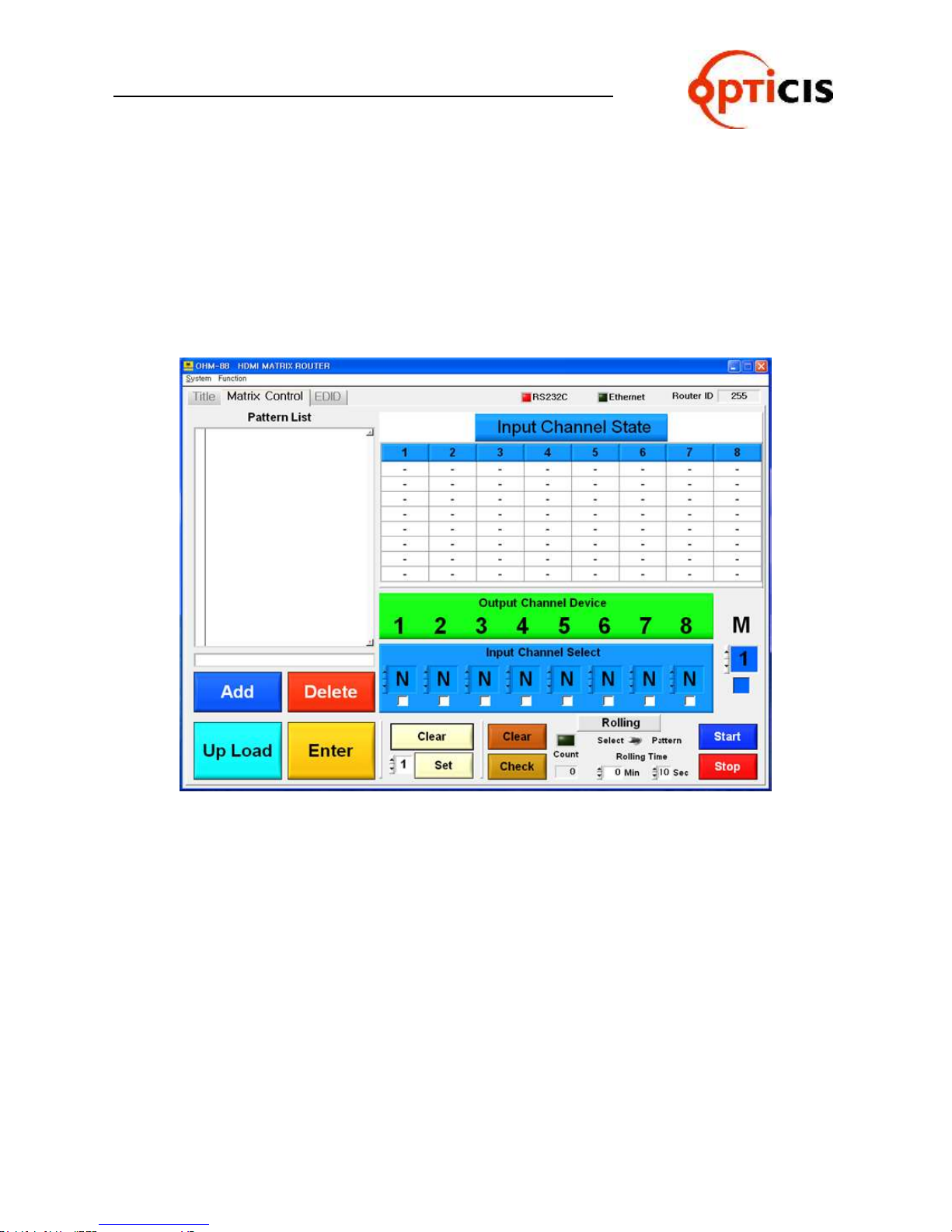
3.4.6 Matrix Control Folder
Set the IN/OUT channel and save the edited data.
Set the Monitoring Output.
Set the Rolling function.
Read switching pattern of IN/OUT CH by selecting Upload button.
OHM-88 Manual Page 51
Page 52
USER MANUAL
HDMI MATRIX ROUTER : OHM-88
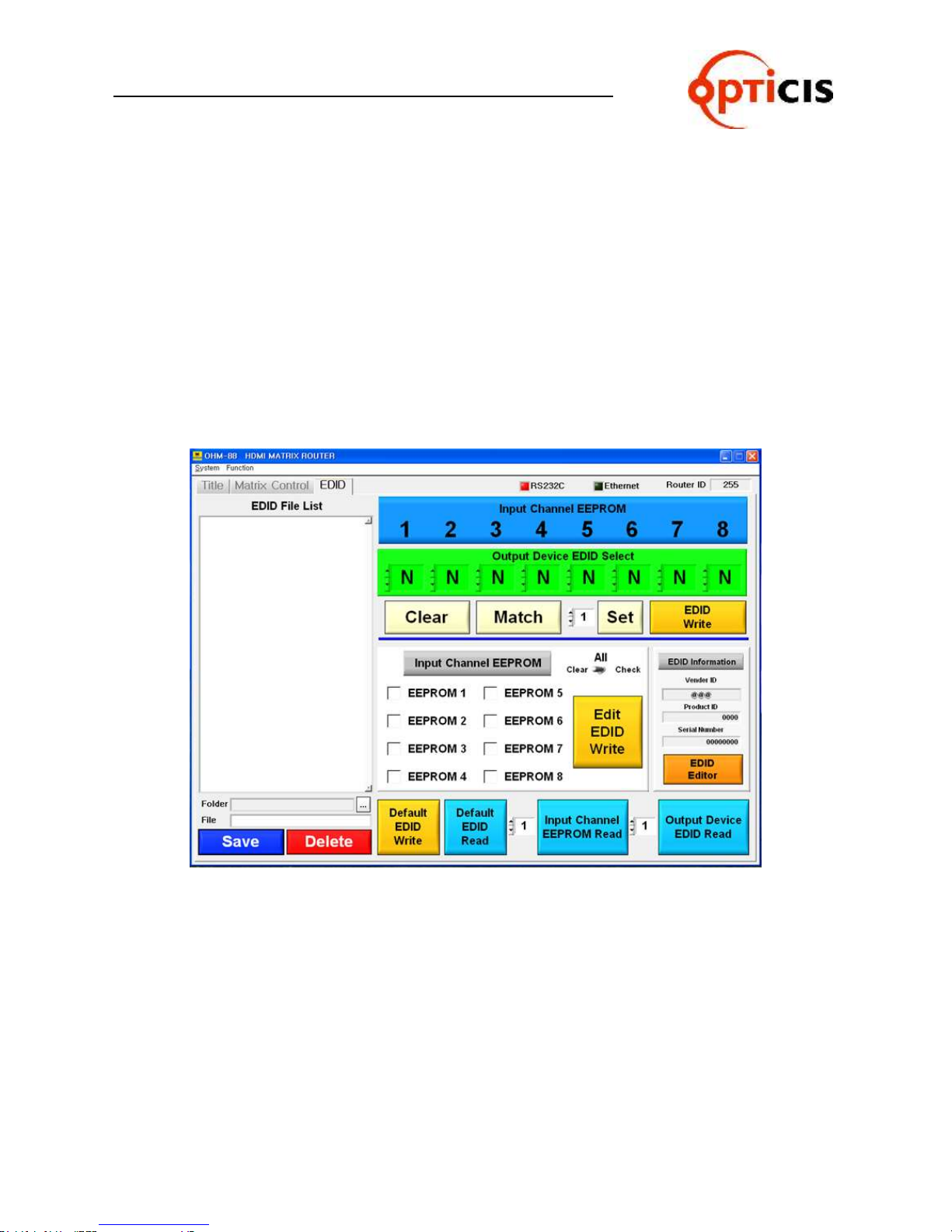
3.4.7 EDID Folder
Store EDID
Read EDID From Output Device
Read EDID From Output Device and store it in Input EEPROM
EDID User defined EDID
Restore defined EDID(in all Input Channel)
One touch store(in all Input Channel)
Store EDID by individual selection
Basic EDID structure: EDID Block 0 [128 bytes]
OHM-88 Manual Page 52
Page 53
USER MANUAL
HDMI MATRIX ROUTER : OHM-88
3.5 Matrix Control Operation
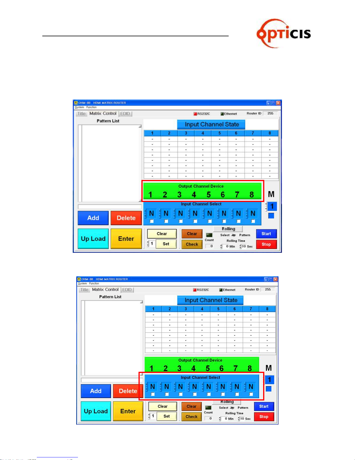
3.5.1 Select Input Channel
1) Output Channel Device is not activated. (It’s fixed always)
2) Select desired input channel
(Click on “N” which is located at the below of Output Channel Device number)
OHM-88 Manual Page 53
Page 54
USER MANUAL
HDMI MATRIX ROUTER : OHM-88
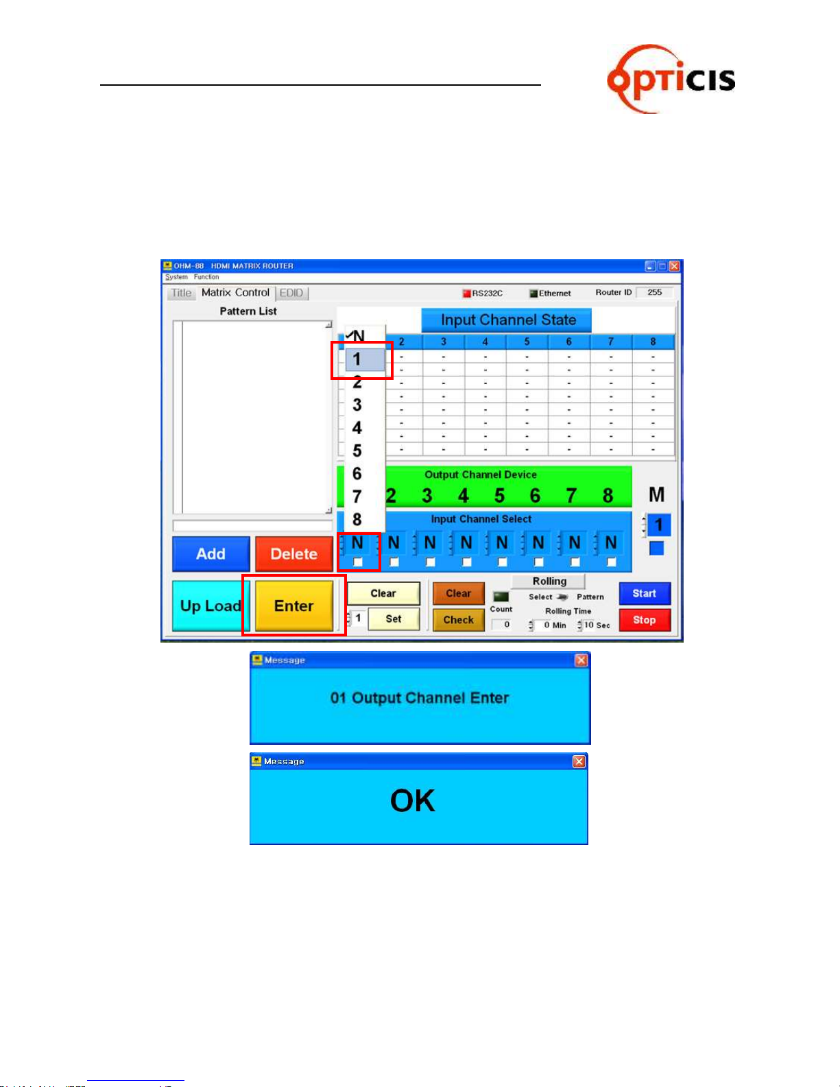
3) Channel link for Input and Output
ex) Link Input Channel 1 to Output Chanel 1
Click on the “N” which is located at the right under Output Channel Device
No. 1 > select 1 > click on the Enter button > OK message
OHM-88 Manual Page 54
Page 55
USER MANUAL
HDMI MATRIX ROUTER : OHM-88
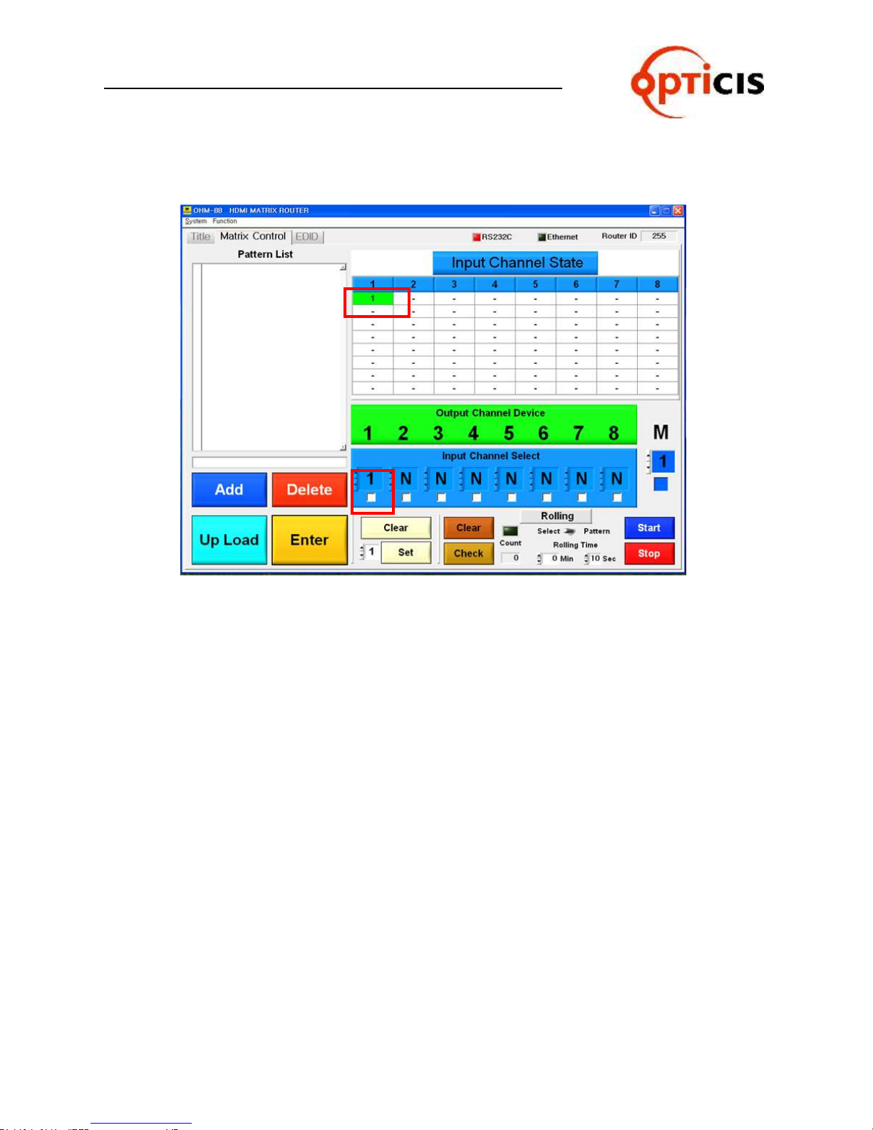
Output CH 1 will be marked in green color in the line of Input CH 1.
OHM-88 Manual Page 55
Page 56
USER MANUAL
HDMI MATRIX ROUTER : OHM-88
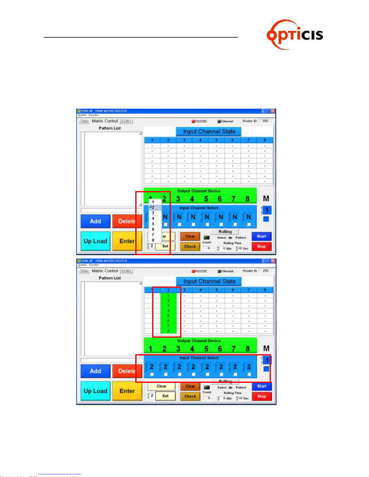
3.5.2 Easy link for Input CH to all Output CH
1) Select Input CH number and Enter button.
ex) Link Input CH 2 to all Output CH:
Select No. 2 > Set button > Enter button
2) If user wants to clear the link setting, select Clear and Enter button.
Clear button > Enter button
OHM-88 Manual Page 56
Page 57
USER MANUAL
HDMI MATRIX ROUTER : OHM-88
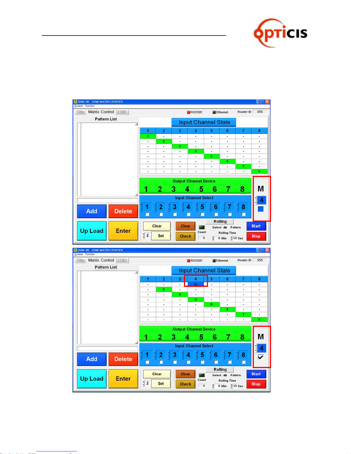
3.5.3 Select Monitoring
Output #1 will be disconnected automatically when monitoring port is
connected and working.
ex) Monitoring for Input CH 4: Select No. 4 > select Check Box
OHM-88 Manual Page 57
Page 58
USER MANUAL
HDMI MATRIX ROUTER : OHM-88
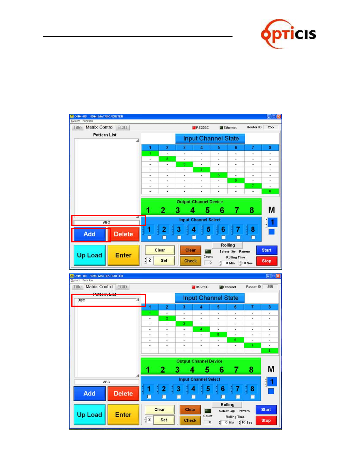
3.5.4 Save Switching Pattern
Select link for Input CH and Output CH > Create Pattern Name >
Select Add button.
ex) Select link for Input CH and Output CH as 1:1 > Write ABC as Pattern
Name > Select Add button
OHM-88 Manual Page 58
Page 59
USER MANUAL
HDMI MATRIX ROUTER : OHM-88
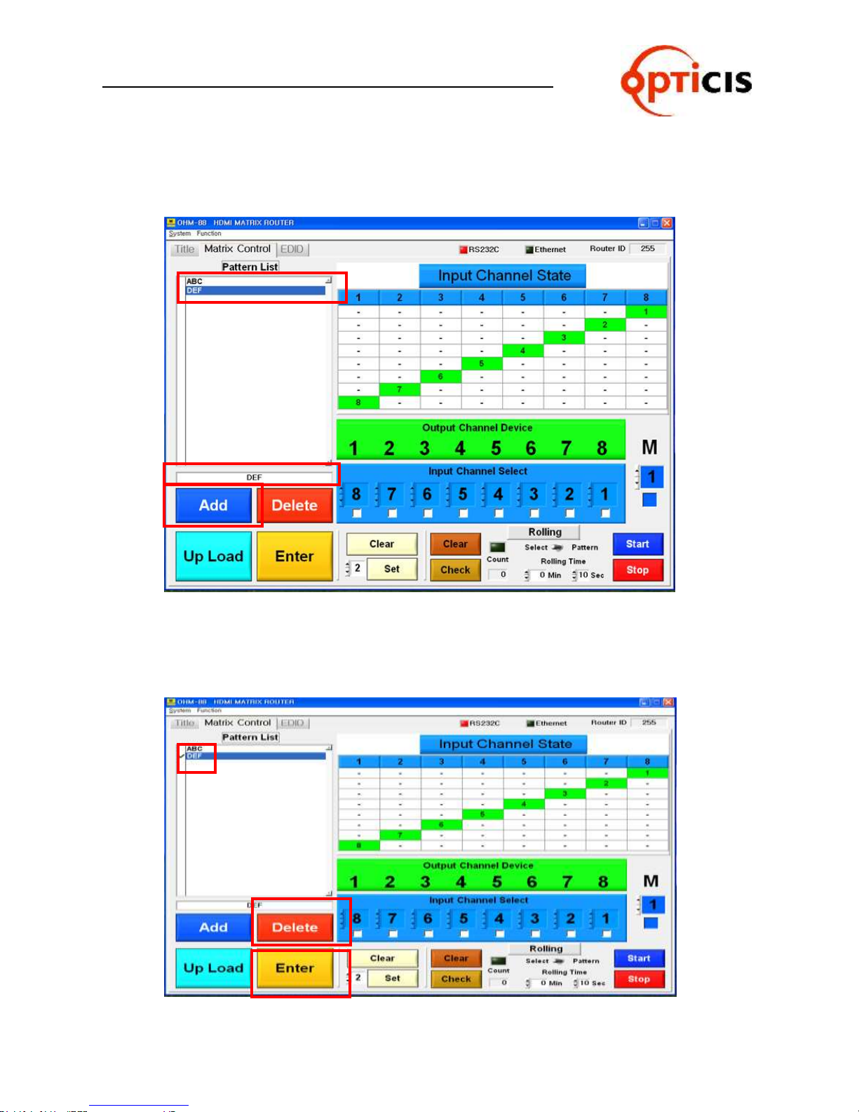
ex) Select link for Input CH and Output CH in reverse order > Create Pattern
Name(DEF) > Select Add button.
In order to delete Pattern Name in the list, the process is:
Select check box for the Pattern Name > Click on the Delete button.
ex) Delete DEF Pattern Name in the list
OHM-88 Manual Page 59
Page 60
USER MANUAL
HDMI MATRIX ROUTER : OHM-88
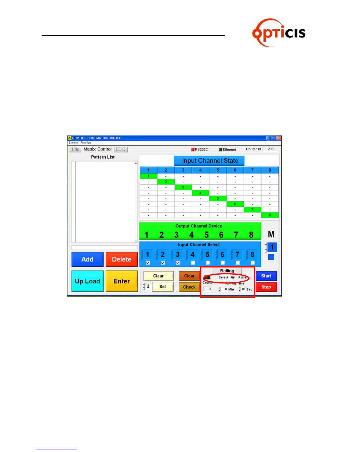
3.5.5 Rolling Function
Allows users to rotate Input sources.
Used to verify all Input-Output connections.
If Output channel was not connected to any Input channel, Check Box would
not be checked.
Must have at least 2 Output Channels.
OHM-88 has two types of rolling function (Select and Pattern).
Select mode process is:
Click on the Select > select Input CH No. > set Rolling Time >
select Start button
Pattern mode process is:
Click on the Pattern > Select Pattern in the list > Start button.
The number of rolling count will be indicated at Count.
OHM-88 Manual Page 60
Page 61

USER MANUAL
HDMI MATRIX ROUTER : OHM-88
3.5.6 Select Rolling Mode
Click on the Select > select Input CH No. > set Rolling Time > select Start button.
For example:
When user selects Input CH 1, 2, 3 to be rolled, the sequence will be
as below.
3.5.7 Pattern Rolling Mode
Click on the Pattern > Select Pattern in the list > Start button.
OHM-88 Manual Page 61
Page 62

USER MANUAL
HDMI MATRIX ROUTER : OHM-88
3.6 EDID Setting
3.6.1 Features:
Store EDID
Read EDID from Output device
Read EDID from Output device and store it in Input EEPROM
EDIT user defined EDID
Restore default EDID (in all Input channels)
One touch store (in all Input channels)
Store EDID by individual selection
Basic EDID structure: EDID Block 0 [128 bytes]
3.6.2 Importance of EDID - Example
Four (4) sources with four (4) different types of displays configured as below: -
Source Input 1 is distributed to Output 1 and 4.
1 Source 1 Display 1
2 Source 2 Display 2
3 Source 3 Display 3
4 Source 4 Display 4
Resolution of Display 1 is 1080p and Display 4 is 1080i
Input 1 EDID must be set a 1080i for all Output 1 and 4 Displays to show 1080i
image.
If Input 1 EDID is set to 1080p, Display 4 cannot display the image
3.6.3 Setting EDID
Select ‘EDID Fold Button’, and go to EDID setting.
This section consist of two functions:
Write EDID Data from Output Device
EDID EDIT & Write EDID Data from PC
OHM-88 Manual Page 62
Page 63
USER MANUAL
HDMI MATRIX ROUTER : OHM-88
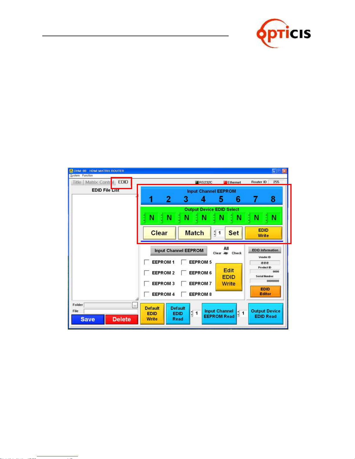
3.6.4 Write EDID data of Output Device to Input CH EEPROM
1) Select EDID, and go to EDID setting.
2) Select Output Device EDID Select No.
3) Verify all Input EEPROM # and selected Output Device #.
4) Select EDID Write button to save the EDID data.
[Note]
Match: Same number will be assigned for EEPROM # and Output # (1 : 1 matching).
Set: Select all the number of Output Device EDID Select with desired number.
Clear: Clear the selected number of Output Device EDID Select.
OHM-88 Manual Page 63
Page 64
USER MANUAL
HDMI MATRIX ROUTER : OHM-88
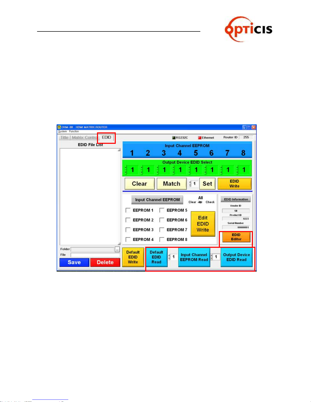
3.6.5 Read EDID
1) Select EDID, and go to EDID setting.
2) Select the number of Input Channel EEPROM Read.
3) Select the number of Output Device EDID Read.
4) Default EDID Data can be read with Default EDID Read button.
If user click on the EDID Editor button, the read EDID Data at the above 2) 3) 4)
process can be checked.
OHM-88 Manual Page 64
Page 65
USER MANUAL
HDMI MATRIX ROUTER : OHM-88
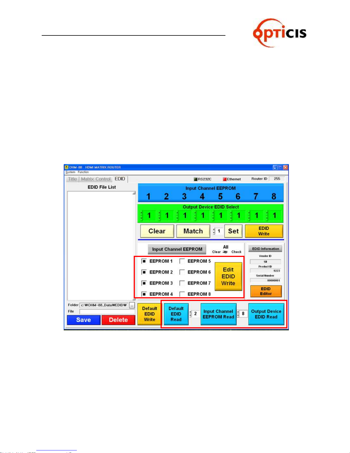
3.6.6 Write the read EDID Data
User can write default EDID Data as following process.
Click on the Default EDID Read button > select Input Channel EEPROM No. > click on
the Edit EDID Write button.
User can write desired Input Channel EDID Data as following process.
Select desired no. at the selection box of Input channel EEPROM Read > select Input
Channel EEPROM No. > click on the Edit EDID Write button.
User can write desired Output Device Channel EDID Data as following process.
Select desired no. at the selection box of Output Device EDID Read > select Input
Channel EEPROM No. > click on the Edit EDID Write button.
OHM-88 Manual Page 65
Page 66
USER MANUAL
HDMI MATRIX ROUTER : OHM-88
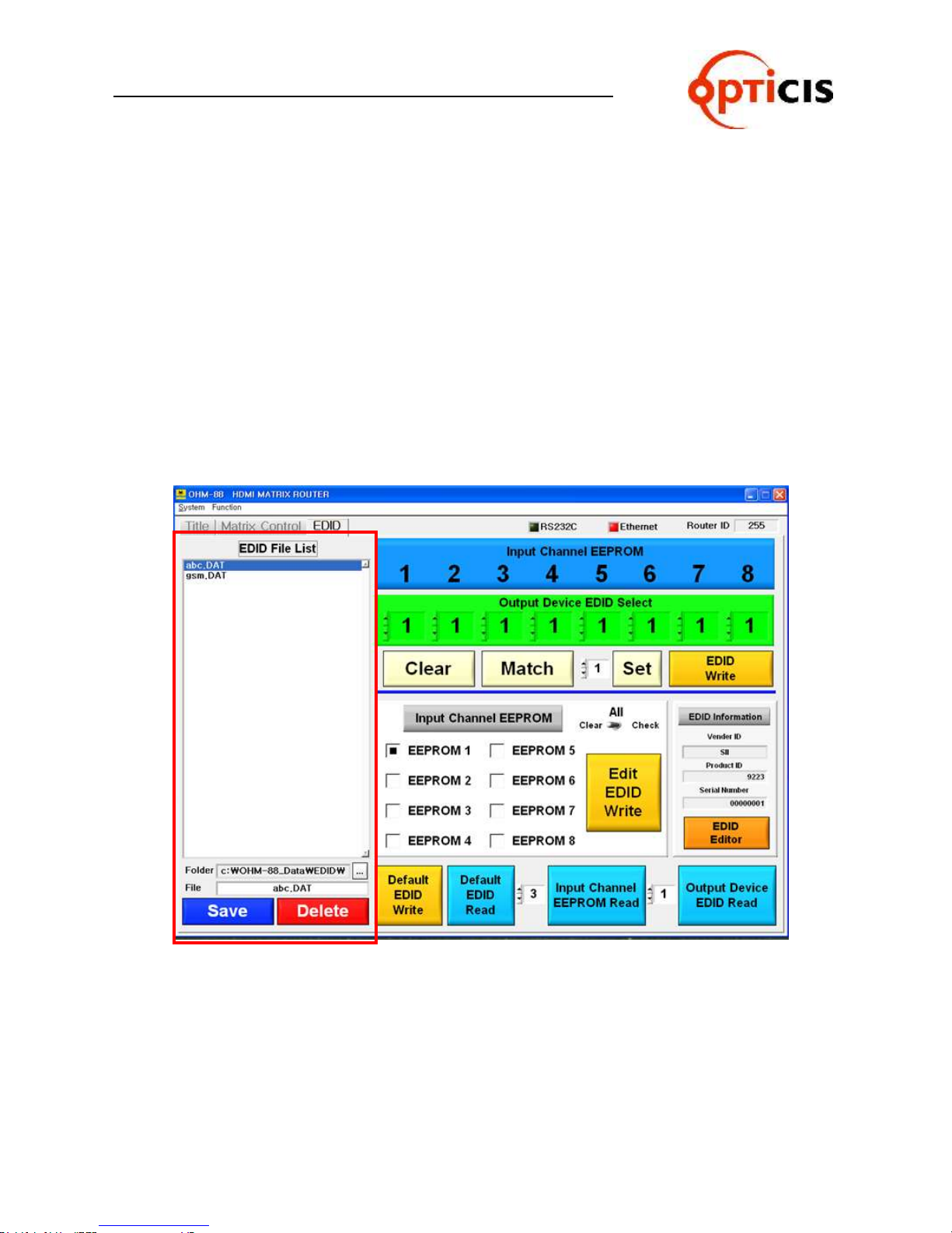
3.6.7 Save the edited EDID Data and open the saved file
The read EDID Data could be saved as a file.
The saved EDID File’s directory is Folder c:\ODM-88_Data\EDID.
File name will be listed with following process.
Input file name at the File line > click on the Save button > the saved file will be listed.
If user wants to delete the save file, the process is as following.
Select desired file which needs to be deleted > click on the Delete button > the file will
be disappeared in the list.
User can write the saved EDID Data to Input Channel EEPROM as following process.
Select desired file in the list > select Input Channel EEPROM No. > click on the Edit
EDID Write button.
OHM-88 Manual Page 66
Page 67
USER MANUAL
HDMI MATRIX ROUTER : OHM-88
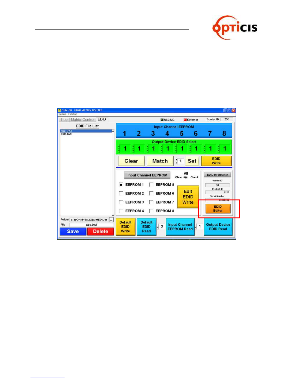
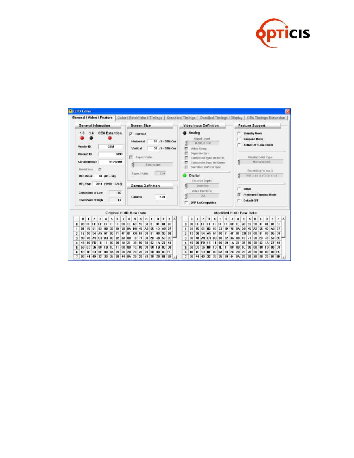
3.6.8 EDID EDITOR
1) Confirm and edit for Input Channel EEPROM, Output Device EDID and Default EDID.
2) The read EDID Data will be displayed when clicking on the EDID Editor button.
3) The edited EDID Data could be saved as a file and saved it to Input Channel
EEPROM.
4) It’s not recommended to edit the EDID Data with no purpose.
OHM-88 Manual Page 67
Page 68
USER MANUAL
HDMI MATRIX ROUTER : OHM-88
Confirm the read EDID Data as a below display.
It will be asked whether save the edited data or not when trying to close the
window.
It can be editable, but it’s not recommended with any purpose.
OHM-88 Manual Page 68
Page 69

USER MANUAL
Problem
Symptom
Remedy
Power
No Power LED
Check the connection of power cord to the OHM-88 and
AC power outlet and that make sure that power switch is
in the ON.
Output
No Output present
Check the Input Output HDMI cables are firmly connected
to each port of OHM-88 and double check the Input
Output connection configuration you want.
The display is not capable of handling graphic resolution.
Check the compatibility of EDID in the EEPROM and
attached displays.
When a single Input is routed to multiple outputs, lower
resolution EDID should be selected.
EX> Input 1 Output 1 (UXGA) & Output 2(SXGA)
If EEPROM 1 store the display 1 EDID (UXGA), the
display 2 (SXGA) will not work due to resolution limit.
The source has stopped sending a graphic signal.
Check that Input source status by connecting it to available monitor without the OHM-88.
HDMI MATRIX ROUTER : OHM-88
4. Troubleshooting
OHM-88 Manual Page 69
Page 70

USER MANUAL
HDMI MATRIX ROUTER : OHM-88
5. Features
This unit is designated to make cross-switch between the 8 HDMI inputs and the 8 HDMI outputs in a way
of any of 8 inputs to one or multiple outputs. Chassis is hardened enough to be applicable in harsh
environments like staging, control room and military.
1) Enables to connect the maximum 8 independent displays.
2) Complies with HDMII-HDCP standard.
3) Each Output port can be used as a Signal-Distributor.
4) Supports Windows PLUG & PLAY function.
5) Offers various control interfaces like Front-Key Input, RS-232 and Ethernet communication.
6) Fulfills real-time display of running status on 20x4 LCD and with illuminated LED type keys.
7) Be rack-mountable with solid 19 inch standard RACK TYPE CASE.
8) Supports real-time Hot Plug Detection and program each EDID to connected HDMI sources as per
user’s specification. (EDID programming option)
9) Offers various options to set EDID to enhance compatibility.
6. Specification
1) Input & Output Video Signals Type: TMDS (Transient Minimized Differential Signal)
2) HDMI Signal Bandwidth: Maximum 1.65Gbps
3) Resolution: VGA (640x480) ~ WUXGA (1920x1200), 480~1080i and 1080p
4) HDCP Compliant
5) 3D Pass-Through
6) RS-232 baud rates: 19,200bps ~115,200bps
7) LAN Port: 10/100 bases
8) AC/DC Power Supply: 110~240V/1.5A, 50~60Hz, DC12V/5A
9) Size: 440 x 165 x 75mm (W x D x H)
10) Weight: 2.5Kg (Router only)
OHM-88 Manual Page 70
Page 71

USER MANUAL
HDMI MATRIX ROUTER : OHM-88
7. Firmware downloading
Router KEY Control
MegaBoot is a firmware update software program for OHM-88
Follow the instructions below to install the MegaBoot software into your PC.
Insert the software CD into your PC and copy the MegaBoot.exe file to your desktop.
Then there will be created below Icon on your desktop.
Connect USB Cable (A Plug –B Plug) over the Router.
Power it on pressing Input key number 2 & 5 at the same time.
Click the AVR Icon to execute setup.exe. The following screen will be displayed.
OHM-88 Manual Page 71
Page 72
USER MANUAL
HDMI MATRIX ROUTER : OHM-88
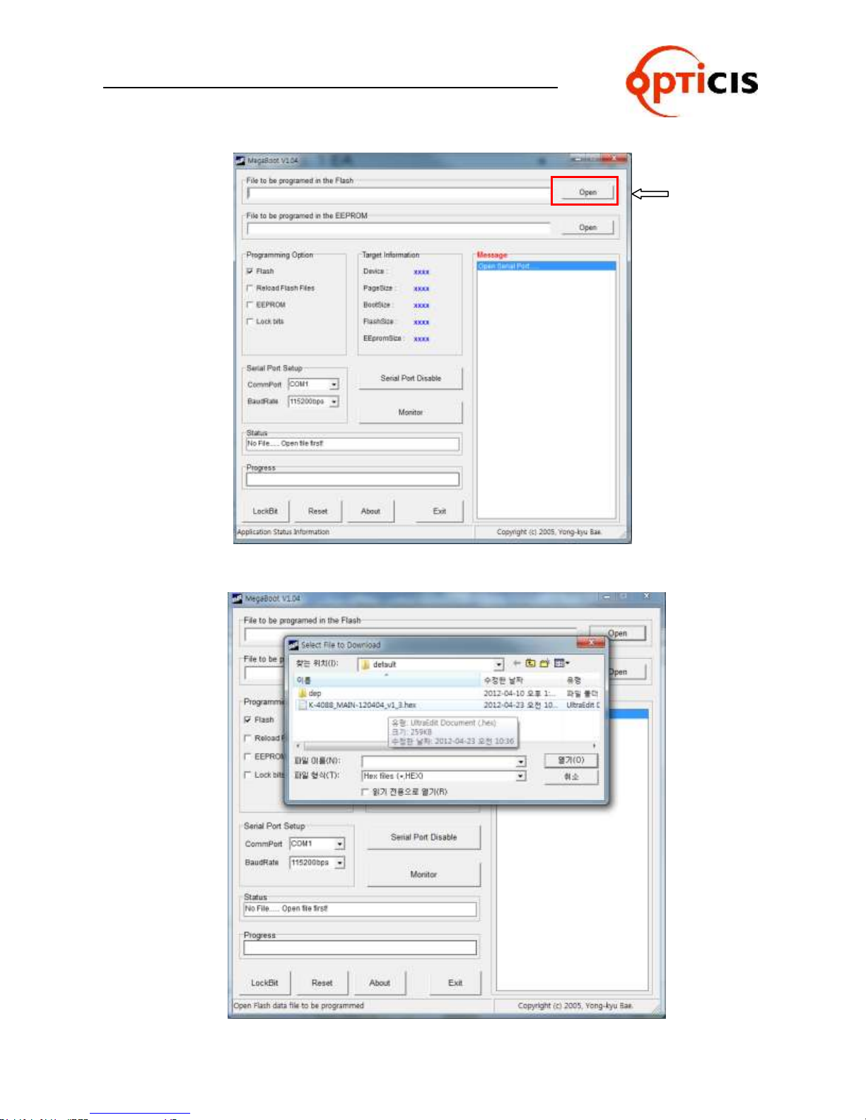
Click on the Open button and select file to be downloaded and click on the open(O) button.
OHM-88 Manual Page 72
Page 73
USER MANUAL
HDMI MATRIX ROUTER : OHM-88
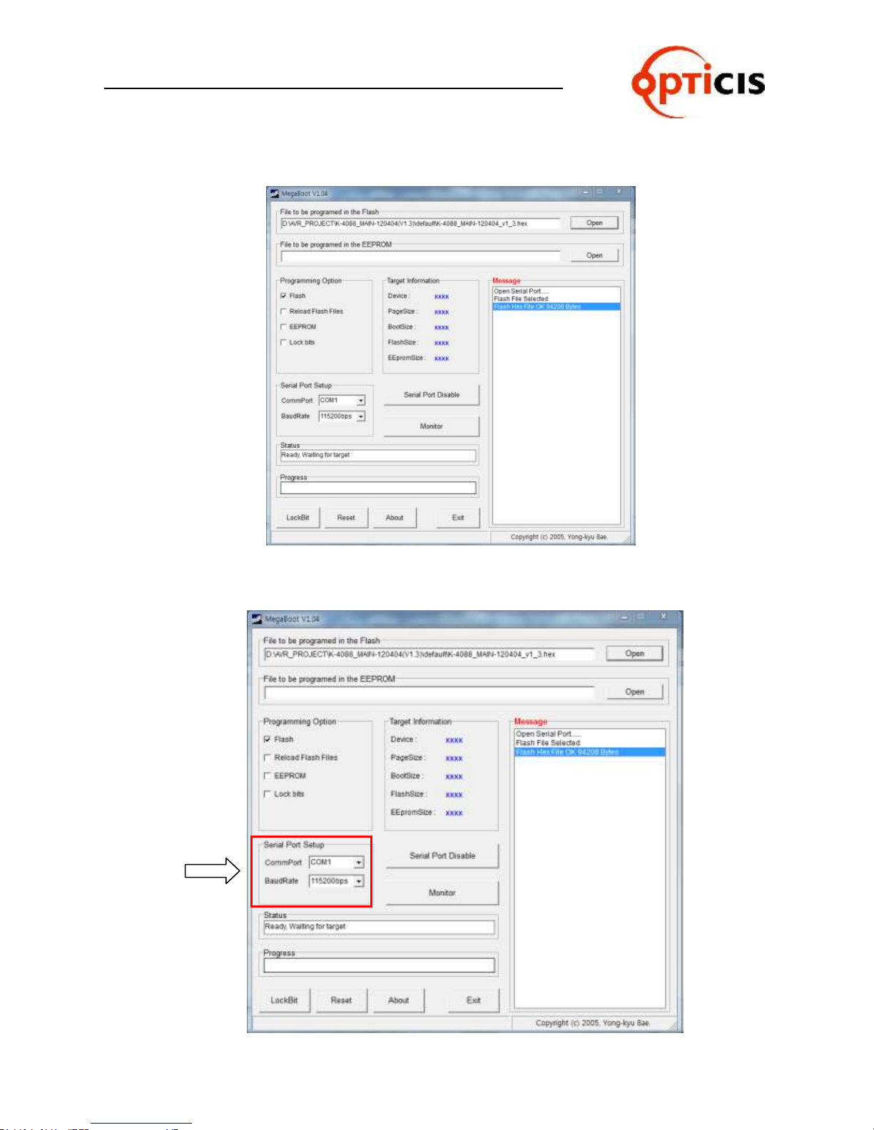
Following screen will be displayed.
Next step is Serial Port Setup.
OHM-88 Manual Page 73
Page 74
USER MANUAL
HDMI MATRIX ROUTER : OHM-88
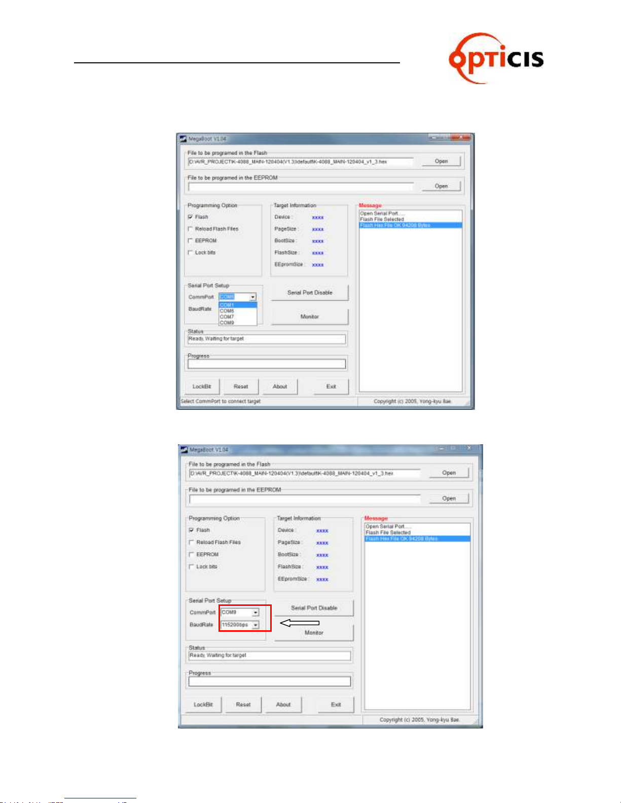
Select proper Comm Port and Baud Rate.
Double click on the “Serial Port Disable” button to execute firmware download.
OHM-88 Manual Page 74
Page 75
USER MANUAL
HDMI MATRIX ROUTER : OHM-88
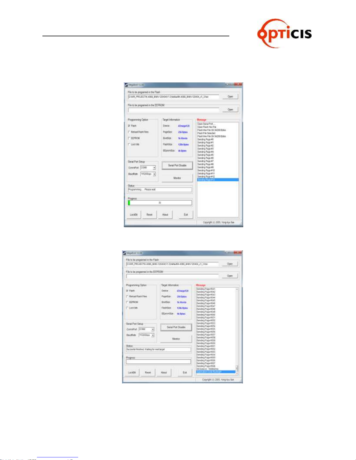
Firmware downloading will be started and the progress will be displayed.
Download completion screen is as below.
Now Router will be operated under new firmware.
OHM-88 Manual Page 75
Page 76

USER MANUAL
Opticis Co., Ltd.
# 16Fl, Kins Tower
8 Sungnam-daero, 331 beon-gil,
Bundang-gu,
Seongnam-si, Gyunggi-do, 463-844
South Korea
Te l: +82 (31) 719-8033
Fax: +82 (31) 719-8032
HDMI MATRIX ROUTER : OHM-88
For order support, please contact your Distributor or Reseller.
For technical support, visit Opticis web site, www.opticis.com or contact [email protected]
OHM-88 Manual Page 76
 Loading...