

opticis M5-2C2-TR User Manual

User’s Manual
M5-2C2-TR
Doc No. : OMM-D130903-M52C2 / Rev2.1
www.opticis.com
Digital Video/Audio
& Serial I/O Extender
Manual Contents
__________________________________________
Manual Contents 1-0
Welcome!, Product Description 1-1
System Requirements for Setup 1-2
Installation 1-3
Booster and EQ Mode Setting 1-7
Troubleshooting, Maintenance, Technical Support 1-8
Product Specifications 1-9
Warranty Information 1-10
Regulatory Statements 1-11
Pictorials
Figure 1 – Overall Digital Video/Audio and Serial I/O
Extender 1-1
Figure 2 – Connection of DVI and RS232 Cable
to Uplink Module 1-3
Figure 3 – Connection of Audio Cable to Uplink Module 1-3
Figure 4 – Selection of Audio Input 1-4
Figure 5 – Connection of Downlink Module 1-4
Figure 6 – Connection of Two(2) CAT5 Cables 1-5
Figure 7 – Wiring Diagram of CAT5 Cable (Direct Type) 1-5
Figure 8 – Connection of AC/DC Power Adaptor 1-5
1- 0 Manual Contents

Welcome!
Congratulations on your purchase of the M5-2C2, Digital Video/Audio and Serial
I/O extender. This manual contains information that will assist you in installing
and operating the product.
Product Description
M5-2C2-TR offers integrated extension of digital video, audio and RS-232
interface up to 50m (160ft) for HDMI/DVI. It maintains HD video signals up to
WUXGA (1920x1200) at 60Hz refresh rate for PC and 1080p for HDTV. It is
compatible with full DDC2B and HDCP. It supports connecting one of 3 different
audio types in the transmitter; RCA, PDIF (Optic) or SPDIF (Coaxial) and
outputting all 3 audio types. RS232 serial interface offers device-to-device and
device-to-controller connections to build up control system for A/V integration.
It is designed to multiplex and de-multiplex the DVI/HDMI video, digital/analog
audio, Display Data Channel (DDC) command interface, High Definition Copy
Protection (HDCP) and serial protocol so as to be linked over two CAT5 cables.
It gives benefits of easy plug-and-go installation and offers you a cost effective
solution for pro A/V system.
Shipping Group of M5-2C2 Digital Video/Audio and RS232 Extender
Tx and Rx boxes: One Uplink module & One Downlink module.
AC/DC power adapter: One +12V/3A unit (including AC cord).
User’s Manual
Option: DVI to HDMI cable, DVI cable, D-sub cable, Audio cable
Figure 1 – Overall Digital Video/Audio and Serial I/O Extender
1-1 Welcome, Product Description
System Requirements for Setup
Hardware requirements
You have a graphic controller card with a DVI port in your
Windows/Mac (Mac is option), or SUN system. It should support
the maximum graphic resolution feature of the display to be
connected.
In case of using a computer, no special memory size, CPU
speed and chipsets are required.
Proper initial trial of the entire platform with its application using
a short length copper cable is recommended prior to install with
the optical link.
Software requirements
No special needs, if the DVI graphic controller and display
peripheral are operational with the platform’s OS and
application.
AC/DC Power Adapter Technical Advisory
The power of M5-2C2 is designed to supply to either Uplink or
Downlink module by plugging the power plug.
1-2 System Requirements for Setup
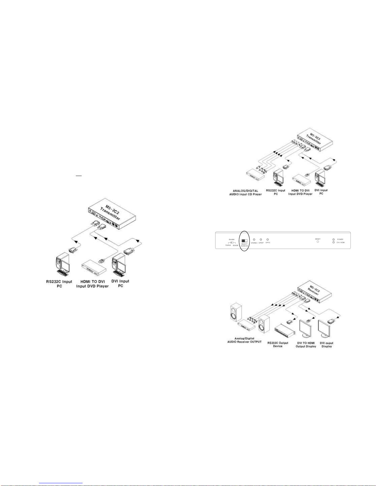
Figure 3 – Connection of Audio Cable to Uplink Module
You can select one of different 3 audio inputs - RCA, S/PDIF(coaxial) and
S/PDIF(optical) - using the switch of front panel. Audio input is changed by
the audio selection switch.
Figure 4 – Selection of Audio Input
Step 4
In the same way as above, connect the Downlink module to the display by
DVI copper cable and to the audio output equipments such as media receiver
or speaker by audio cable. The RS232 devices near the display can be
connected by RS232 copper cables also.
Figure 5 – Connection of Downlink Module
1-4 Installation (continued)
Installation
Important: Please use the installation procedure below. Improper, or no
operation may result if the start-up sequence is not correctly followed.
Step 1
Carefully unpack the contents of the shipping group.
Step 2
With system power turned off, connect the Uplink module to the DVI
receptacle of PC or other video source equipment by a DVI copper cable or a
HDMI to DVI cable. If necessary, connect the RS232 cable plugs to each Dsub 9-pin connector on PC and Uplink module.
Figure 2 – Connection of DVI and RS232 Cable to Uplink Module
Step 3
Connect the Uplink module to the audio source equipment by audio cables
such as RCA, S/PDIF coaxial cable and S/PDIF optical fiber.
1-3 Installation
 Loading...