

opticis M1-3R2VI-DU User Manual

User’s Manual
for the M1-3R2VI-DU
Optical DVI Dual Link
Extension Module
®
Manual Contents
__________________________________________
Manual Contents 1-0
Welcome!, Product Description 1-1
System Requirements for Setup 1-2
Installation – Direct DDC 1-3
Installation – Virtual DDC 1-5
Troubleshooting, Maintenance, Technical Support 1-7
Product Specifications 1-8
Warranty Information 1-9
Regulatory Statements 1-10
Pictorials
Figure 1 – Overall Optical DVI Module 1-2
Figure 2 – Connection of DVI cable between
Transmitter box and PC 1-3
Figure 3 – Connection of DVI cable between
Receiver box and the display 1-3
Figure 4 – Connection of 4 LC fiber cables and
a DDC cable 1-4
Figure 5 – Connection of AC/DC power adaptor 1-4
Figure 6 – Connection for Self-EDID programming 1-5
Figure 7 – Connection of 4 LC fiber cables 1-6
Figure 8 – Connection of AC/DC power adaptor 1-6
1- 0 Manual Contents
Welcome!
Congratulations on your purchase of the M1-3R2VI-DU, Optical Dual Link DVI
Module. This manual contains information that will assist you in installing and
operating the product.
Product Description
The M1-3R2VI-DU module offers 100meters extension of dual link highresolution digital graphic data over fiber, directly connected between PC and
displays, supporting dual link DVI. Two boxes, located one by the PC and the
other by the display are connected to each of them with a 1.0 m dual link DVI
copper cable. Between two boxes, 7 channels (R, G, B, Clk, R2, G2, B2) of
graphic data enables to be transmitted over the 4 LC single or multi-mode fiber
bundled cable and the Digital Display Channel (DDC2B) interface is performed
over a CAT5e cable, so called as DDC cable, which has RJ-45C connectors.
The M1-3R2VI-DU also provides 2km extension over 4 single mode fibers
using virtual DDC mode without CAT5e connection. The EDID (Extended
Display Identification Data) in a display can be read and restored by just
plugging once transmitter to the display. This Self-EDID programming feature
makes the installation of M1-3R2VI-DU easier and more flexible at any variable
resolution display systems.
For your convenience, Factory EDID default is set to WQXGA (2560x1600).
Shipping Group of M1-3R2VI-DU Optical Dual Link DVI Module
Tx and Rx boxes: One (1) Transmitter (Tx) Box and One (1)
Receiver (Rx) Box.
Two (2) dual link DVI copper cables: 1.0m
AC/DC power adapter: One (1) +24V unit
User’s Manual
Option: DDC cable (UTP for LAN) with RJ-45C.
Option: 4 LC Patch Cord fiber bundled cable (Single or Multi
mode glass fiber).
Option: Two +24V AC/DC power adapters are required for virtual
DDC.
1-1 Welcome, Product Description
System Requirements for Setup
Hardware requirements
You have a Media Receiver or a graphic controller card with a
Dual link port in your Windows/Mac (Mac is option), or SUN
system. It should support the maximum graphic resolution
feature of the display to be connected.
In case of using a computer, no special memory size, CPU
speed and chipsets are required.
Proper initial trial of the entire platform with its application using
a short length copper cable is recommended prior to install with
the optical link.
Software requirements
No special needs, if the Dual link graphic controller and display
peripheral are operational with the platform’s OS and
application.
AC/DC Power Adapter Technical Advisory
Direct DDC: One power adaptor is required to supply power to both
modules of Tx and Rx over the CAT5e cable by plugging the power
jack to either of their power plugs.
Virtual DDC: Two power adapters are required to supply power to
Tx and Rx module due to no use of the CAT5e cable for DDC.
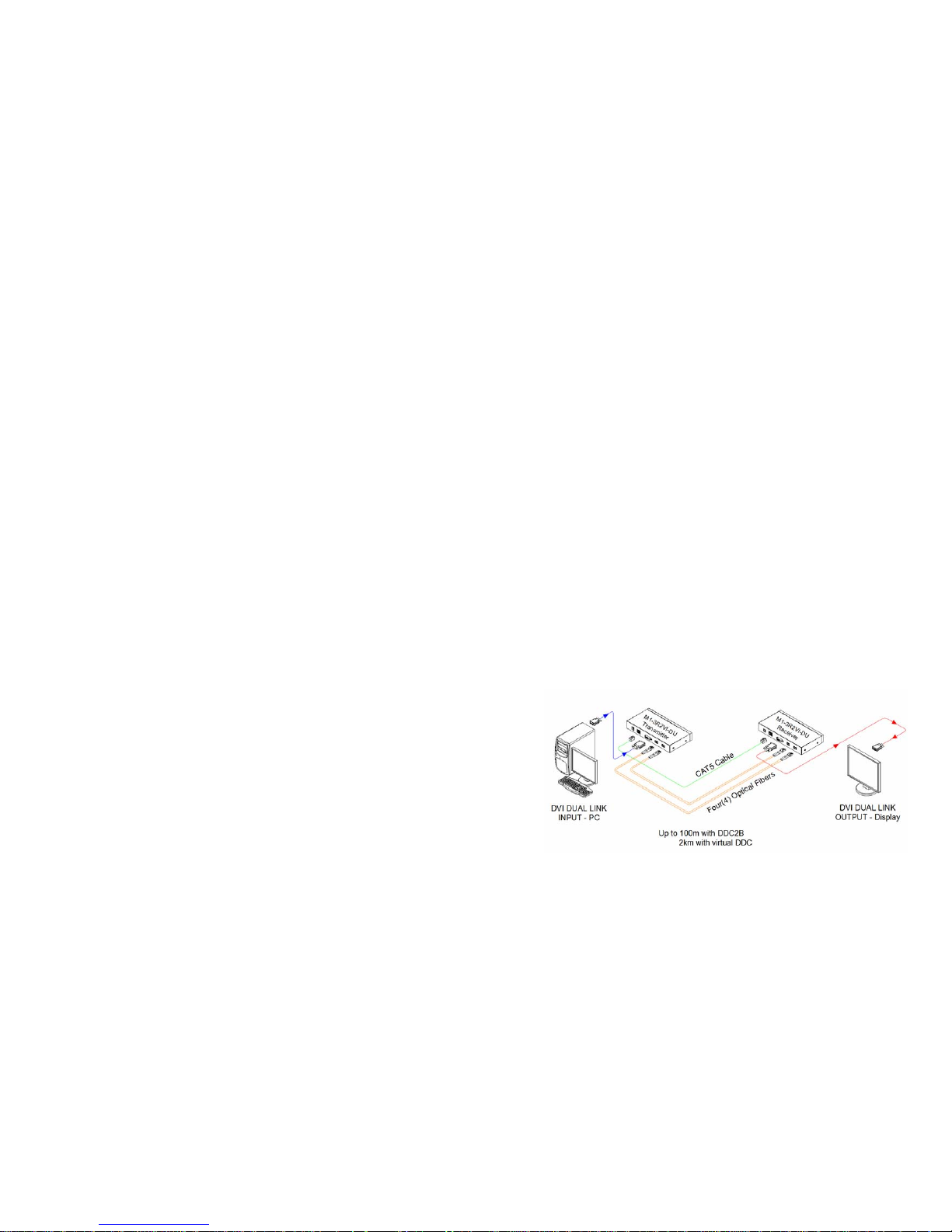
Figure 1 – Overall Optical dual link DVI Module
1-2 System Requirements for Setup

4
Installation – Direct DDC (Use this menu when DDC through CAT5e)
Important: Please use the installation procedure below. Improper, or no
operation may result if the start-up sequence is not correctly followed.
Step 1
Check that the transmitter and receiver are turned off. Set “DDC connection”
switch to “Direct DDC” position on the front panel of the transmitter.
Step 2
Connect the upstream Transmitter box to the DVI receptacle of PC through
one dual link DVI copper cable (included).
Figure 2 – Connection of DVI cable between Transmitter box and PC
Step 3
In the same way as above, connect the Receiver box into the DVI receptacle of
the display through the other dual link DVI copper cable.
Figure 3 – Connection of DVI cable between Receiver box and the display
Warning: Please DO NOT look directly into the LC receptacles of the
Transmitter box, while it is turned on, although this product is strictly regulated
enough to operate under the Laser Class I, classified by CDRH/FDA for eye
safety.
1-3 Installation
Step 4
Remove the module dust covers and connect each duplex LC fiber cable one by
one to each of 4 LC receptacles of the Transmitter and Receiver boxes, as shown
in Fig. 4. Plug channel 1 to 1 and channel 2 to 2. Carefully recheck polarities and
ensure the duplex connectors are fully engaged.
Step 5
Connect each RJ-45C of the CAT5e cable to each RJ-45C receptacle of the
Transmitter and Receiver boxes.
Figure 4 – Connection of 4 LC fiber cables and a DDC cable
Note : Connection for single link DVI
For single link DVI use, one duplex fiber or two simplex fibers are required
to be plugged to one port marked “Channel 1”.
Step 6
Connect an AC/DC power adapter to the DC input terminal either of Transmitter
and Receiver boxes as your availability of AC outlets.
Figure 5 – Connection of AC/DC power adaptor
Step 7
Plug the AC/DC power adapter into AC outlet. Turn ON the PC.
Tip 1: After initial installation as guided in the above, we recommend you to power
On and Off while all connections are set and the Tx/Rx boxes are powered in.
1-4 Installation (continued)
 Loading...