

opticis KVMX-200-TR User Manual
One (1) fiber DVI KVM Extender,
KVMX-200-TR
User’s Manual
Doc No. : OKM-D140704-KVMX-200 / Rev1.0
© 2014 Opticis Co., Ltd. All Rights Reserved
Revision 1.0 4, July, 2014
Opticis Locations
Headquarters
Opticis Co., Ltd.
# 16Fl, Kins Tower
8 Sungnam-daero, 331 beon-gil,
Bundang-gu,
Seongnam-si, Gyunggi-do, 463-844
South Korea
Te l: +82 (31) 719-8033
Fax: +82 (31) 719-8032
www.opticis.com
For order support, please contact your Distributor or Reseller.
For technical support, check with the Opticis web site www.opticis.com or
contact techsupp@opticis.com.
Welcome!
Congratulations on your purchase of the KVMX-200-TR, One (1) fiber DVI
Optical KVM Extender. This manual contains information that will assist you in
installing and operating the product.
Product Description
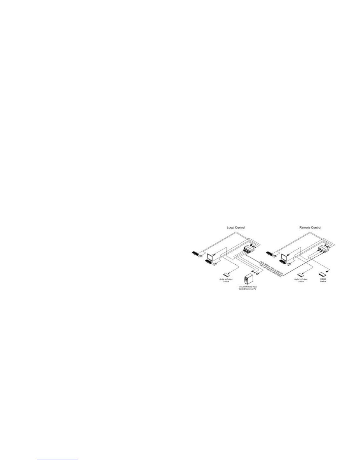
New One (1) fiber DVI optical KVM extender, KVMX-200-TR transmits DVI,
USB HID, PS/2, RS-232 and bi-directional stereo audio signal up to 1.0km
(3,280feet) over one (1) LC optical fiber. As an option, you can select one (1) or
two (2) fibers connection by SFP module.
Designed for high resolution performance, it guarantees lossless image quality
and no frame dropping to deliver perfect graphic data transmission up to
WUXGA (1920x1200) at 60Hz.
It provides Auto-mix EDID programming feature that reads EDID information of
both local side and remote side displays and then, detects the lowest resolution
of them. It makes the installation of KVMX-200-TR more easy and flexile at any
variable resolutions.
Figure 1– Connection Diagram
Shipping Group of KVMX-200-TR
One (1) Transmitter (Tx) and One (1) Receiver (Rx)
Two (2) +12V/3A units (including AC cord).
User’s Manual
Option: Remote console switch (LSKP-10030 & Indicator (RSKP-
1003),1RU mounting rack (OPMCR-1U),bracket (OPMCB), fiber-optic
cable
1-1 Welcome, Product Description, Shipping Group
Manual Contents
__________________________________________
Manual Contents 1-0
Welcome, Product Description 1-1
System Requirements for Setup 1-2
Installation 1-3
Switch Operation Guide 1-5
Troubleshooting, Maintenance, Technical Support 1-6
Product Specifications 1-7
Features, Ordering Information 1-9
Firmware download 1-10
Warranty Information 1-13
Regulatory Statements 1-14
Pictorials
Figure 1 – Connection Diagram 1-1
Figure 2 – Connection of Transmitter 1-3
Figure 3 – Connection of Receiver 1-4
1-0 Manual Contents

System Requirements for Setup
Hardware requirements
You have a graphic controller card with a DVI port in your
Windows/Mac (Mac is option), or SUN system. It should support
the maximum graphic resolution feature of the display to be
connected.
In case of using a computer, no special memory size, CPU
speed and chipsets are required.
Proper initial trial of the entire platform with its application using
a short length copper cable is recommended prior to install with
the optical link.
Software requirements
No special needs, if the DVI graphic controller and display
peripheral are operational with the platform’s OS and
application.
1-2 System Requirements for Setup
Installation
Important: Please keep the installation procedure below. Improper or no
operation may result if the start-up sequence is not correctly followed.
Step 1
Carefully unpack the contents of the shipping group.
Step 2
Power on the PC and display(s).
Step 3
Plug the 12V power adapters to the +12V DC jack on the rear side of
Transmitter and Receiver. Then, the Power LED (blue) will be turned on.
Step 4
Connect the DVI IN port of Transmitter to the DVI output of a PC over a DVI
copper cable. Connect USB IN port of Transmitter to PC over one (1) USB AB cable for Keyboard and Mouse. Then, the LED (blue), next to the USB IN
port will be turned on.
If necessary, connect the RS-232, DIO, audio, and mic cables to RS-232, DIO
1IN/GND/2OUT, audio IN/OUT, and mic IN/OUT connectors on the front side
of Transmitter.
Step 5
Connect the Local Display port of Transmitter to a DVI display over a DVI
copper cable. Attach keyboard and mouse to the USB HID port or PS/2 port
for local control. Then, the LED (blue) will be turned on. You may skip Step 5
if you don’t need local control.
Figure 2– Connection of Transmitter
1-3 Installation
 Loading...