

opticis IPVDS-500-ED, IPVDS-500-E, IPVDS-500-D User Manual
- 1 -
4K HDMI IP Video Wall Controller
IPVDS-500-ED
User’s Manual
Doc No. : OIPVDS-D160722 / Rev1.0
WWW.OPTICIS.COM

- 2 -
* Index
1. Product Description .......................................................................................................................- 4 -
2. Main Features ...............................................................................................................................- 5 -
3. Supporting Video Resolutions for Input / Output ..........................................................................- 6 -
4. Shipping Group .............................................................................................................................- 6 -
5. Systems Requirements for Setup .................................................................................................- 6 -
6. Connector descriptions .................................................................................................................- 7 -
7. LED Indication ...............................................................................................................................- 9 -
8. Connection (Installation) ............................................................................................................ - 10 -
9. SW & Factory Reset .................................................................................................................. - 11 -
10. PC Program (Video Wall Control Software)............................................................................... - 11 -
10.1 PC program Installation and Login / Logout ........................................................... ……….- 11 -
10.2 Menu items for device setup and system configuration .................................................... - 13 -
10.3 Getting Started for Video Wall ........................................................................................... - 17 -
11. Prodcut Specifications ............................................................................................................... - 30 -
12. Troubleshooting ......................................................................................................................... - 31 -
13. Warranty Information ................................................................................................................. - 33 -

- 3 -
*. Pictorials
Figure 1 – Connection diagram ................................................................................................ ……….- 4 -
Figure 2 – Video Wall software ................................................................................................ ……….- 5 -
Figure 3 – Program Installation .............................................................................................. ……….- 12 -
Figure 4 – Log in .................................................................................................................... ……….- 12 -
Figure 5 – Ribbon menu ......................................................................................................... ……….- 13 -
Figure 6 – User setup ............................................................................................................. ……….- 13 -
Figure 7 – Advanced setup .................................................................................................... ……….- 14 -
Figure 8 – Firmware upgrade ................................................................................................. ……….- 15 -
Figure 9 – Icon menu .............................................................................................................. ……….-16 -
Figure 10 – Layout Manager .................................................................................................. ……….- 17 -
Figure 11 – Display Placement .............................................................................................. ……….- 18 -
Figure 12 – Layout setup ....................................................................................................... ……….- 18 -
Figure 13 – Searching ............................................................................................................ ……….- 19 -
Figure 14 – Device setting ..................................................................................................... ……….- 20 -
Figure 15 – EDID setup .......................................................................................................... ……….- 21 -
Figure 16 – Display Placement page setup ........................................................................... ……….- 22 -
Figure 17 – Display setup ...................................................................................................... ……….- 23 -
Figure 18 – Audio setup ......................................................................................................... ……….- 24 -
Figure 19 – Audio setup apply ............................................................................................... ……….- 25 -
Figure 20 – Client device setup ............................................................................................. ……….- 25 -
Figure 21 –Real displays with OSD on .................................................................................. ……….- 26 -
Figure 22– Layout setup ........................................................................................................ ……….- 26 -
Figure 23 – Stretch Layout ..................................................................................................... ……….- 27 -
Figure 24 – Video overlay ...................................................................................................... ……….- 27 -
Figure 25 – Video overlay setup ............................................................................................ ……….- 28 -
Figure 26 – Preset open/save ................................................................................................ ……….- 28 -
Figure 27 – Apply ................................................................................................................... ……….- 29 -
- 4 -
1. Product Description
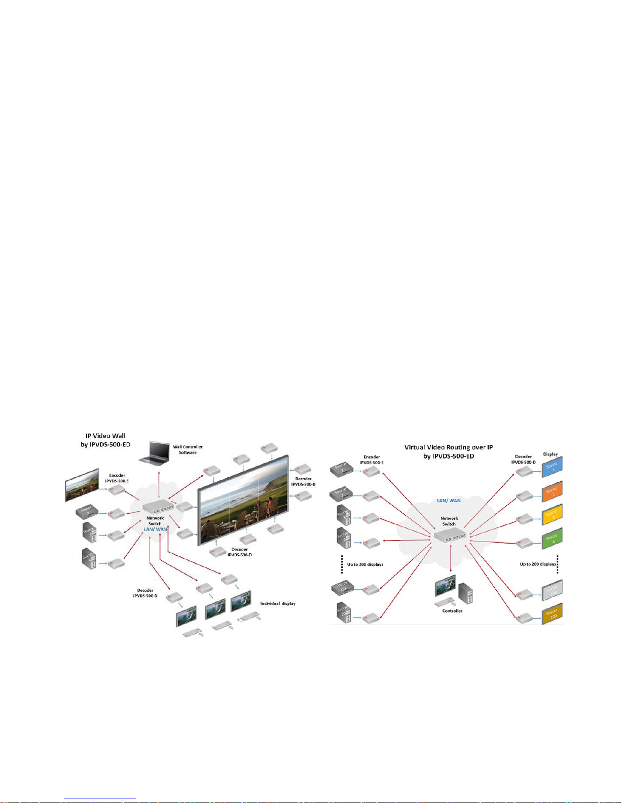
4K HDMI IP Video Wall Controller IPVDS-500-ED is an integrated control solution for playing
audio/video of multi-sources (such as PC, Media player, DVD or Blu-ray) on video wall displays and
many individual displays simultaneously.
It offers advanced wall management service in order to give perfect solution for accommodating
medium-sized and larger multi-board configurations such as control room, security, traffic
management and small-scale single-board systems for conference and classroom presentations.
The transmitter, IPVDS-500-E (Encoder) connected to a HDMI source, encodes the video with data
and transmits it over Ethernet. The receiver, IPVDS-500-D (Decoder) connected to a display, receives
the encoded signal over network and decodes it to regenerate the video and data for users.
The provided PC program “Layout Manager” makes the creation, editing, overlay, saving and pre-set
mode of wall layouts possible. It has an easy-to-use graphics user interface where any operation can
be set up by simple mouse clicks and drags.
IPVDS-500-ED also makes the transmitters and receivers units in the network to be configured to
individual IP address and helps the any of receivers to be connected simultaneously to any
transmitter within the network to create a virtual cross point matrix system as well as audio and video
system widely used in Pro-AV installation.
[Figure 1 - Connection diagram]

- 5 -
2. Main Features
- TCP/IP based IP network: 100/1000 Base-T Ethernet with CAT5e or CAT6 cables
- Supports resolution up to 4K (3840x2160 at 30Hz) or full HD 1080p at 60Hz.
- Supports up to 8 x 8 Video Wall with multi-sources.
- Offers merge, overlay, and split Video Wall layouts via provided PC program.
- Provides pre-set mode to save and load the current layout.
- Provides Analog/HDMI audio input and output.
- Offers M:N Virtual Matrix supported: multicasting up to 200 clients
- Fast switching time / Low video latency
- Transmits HDMI/DVI, USB, RS-232, Audio, DIO signals via IP Network.
- Provides HDMI loop-thru port for Local display.
- Provides 1U rack (model: OPSCR-1U), Optional.
- Provides Mounting bracket (model: OPSCB): VESA 75,100 standard, Optional.
♦ Video Wall Controller SW
- Provides PC Program for Users
Controls PC Apps for Video Wall and Individual Displays
Drag and Drop operation of Mouse for Host Allocation and Preview
Offers allocation, merge, split, overlay, and clear on Layout Manager
Provides preview scene before to apply it to real monitors.
Provides 99 Presets for user defined layout (Save and Load).
Bezel Compensation in 0.1mm units
[Figure 2 –Video Wall software]
♦ Application
- Control Room
- Traffic Control System
- Security and Education
- Digital Signage / Pro AV for Video Wall & individual display

- 6 -
3. Supporting Video Resolutions for Input / Output
1) HDMI 1.4 3840x2160p/24/25/30Hz
2) HDMI 1.4/HDTV up to 1920x1280p60Hz
3) VESA Digital up to 1920x1200p60Hz
Note: Some PC resolutions may not work properly.
4. Shipping Group
- IPVDS-500-E: TX (Encoder) or IPVDS-500-D: RX (Decoder)
- AC / DC power adaptor: One (1) unit of 5V / 2A
- One (1) HDMI male to male cable (1.2m)
- One (1) Mini-USB Cable for PC
- User’s manual
As an option,
- RS-232 cable: DB-9 male to 3Pin terminal block
- Mounting bracket (OPSCB) complying with VESA 75, 100.
5. Systems Requirements for Setup
♦ Hardware requirements
▶ You must have a HDMI graphic controller or card having a HDMI or DVI port in your PC
or any other equipment being used.
▶ It should support the maximum graphic resolution of displays.
▶ No special requirements for memory size, CPU speed and chipsets, if you’ve already
properly installed your HDMI graphic controllers or cards.
♦ Software requirements
▶ You need to check OS version of your PC or any other equipment being used. [TBD]

- 7 -
♦ Network requirements
▶ You may need Ethernet switch (L2 or L3) as a switching hub or router for connecting
multiple IPVDS -500-EDs on Local LAN or Intranet. Network speed of each port of Ethernet
switch requires 100/1000Mbps and the network switch has to support Jumbo frame and
multicasting protocol between L3 Switch.
▶ For technical support, visit Opticis web site, www.opticis.com, or contact
techsupp@opticis.com
▶ But, point-to-point connection between one pair of IPVDS-500-ED can be directly
connected (with CAT5e or CAT6) without network switch.
♦ Control PC requirements
▶ You need to check OS version of your PC for Video Wall Control SW.
▶ Requirements: Window7 or higher version (Optionally including Window XP)
♦ AC / DC Power Adapter Technical Advisory
▶ The IPVDS-500-ED is designed to use mainly external +5V AC / DC power adaptor. The
internal power supplied through a HDMI pin (#18) from the graphic source is used to
identify normal connection between a source and TX, IPVDS-500-E.
6. Connector descriptions
▶ 5V AC / DC Power (TX & RX):
Connect the 5V AC / DC Power Adaptor to the connector of each device. When the 5V
AC/DC Power Adaptor is connected to the device, the power LED is turned on. For more
information on LEDs, refer to “LED indication”.
▶ HDMI IN (TX)
: Connect a video source (such as a PC) to HDMI IN receptacle over HDMI cable.
▶ HDMI OUT (RX)
: Connect a digital display to HDMI OUT receptacle over HDMI cable.
▶ Local Display (TX)
: Connect a digital display to Local Display receptacle over HDMI cable.
▶ RJ-45 (TX & RX)
: Connect a RJ-45 network cable (CAT5e / CAT6) to the connector.
- 8 -
▶ mini USB port (TX)
: Connect a USB port in PC to this connector for HID mouse or Keyboard.
▶ USB A Type (TX)
: Connect a mouse and/or a keyboard with 2 port USB hub.
▶ Dual USB A Type (RX)
: Connect a mouse and/or a keyboard to these connectors.
▶ RS-232 (TX & RX): Optional
▶ DIO (TX & RX): Optional
Note1: If you change a video source to another one, you have to reset the power of all TXs
and RXs by re-plugging of the +5V power adaptor.
Note2: If you want to use the function of RS-232 & DIO, please contact sales@opticis.com.
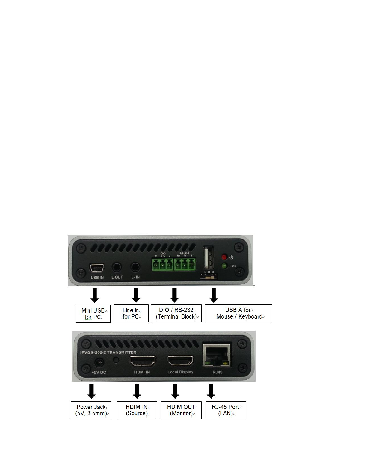
♦ IPVDS-500-E, TX Front & Back
♦ IPVDS-500-E, TX Back
Mini USB
for PC
DIO / RS-232
(Terminal Block)
Line in
for PC
- 9 -
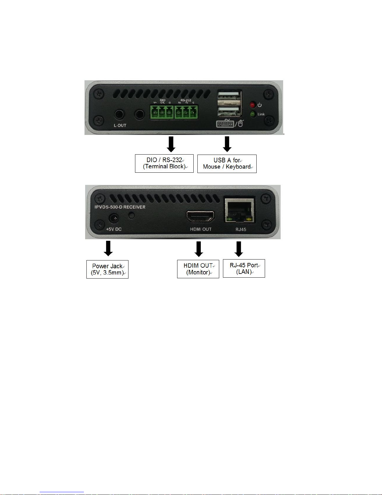
♦ IPVDS-500-D, RX Front & Back
7. LED Indication
The two (2) LEDs on the front panel of IPVDS-500-ED indicate power and network status.
♦ Power status LED (Red)
The red LED will be turned on when 5V power is applied.
♦ Link LED (Green)
If the green LED turns on at TX and RX, IPVDS-500-ED is ready to operate as Video Wall
display.

- 10 -
8. Connection (Installation)
Important: Please follow the installation procedure below. Improper or no operation may be
resulted, if the start-up sequence is not followed correctly.
Step 1
Carefully unpack the contents of the shipping group.
Step 2
Turn on the PC, display, and network switch.
Step 3
Turn on the PC for Video Wall control SW and connect network cable (CAT5e or CAT6) to
network switch.
Step 4
Connect HDMI IN port in IPVDS-500E (TX) to the PC by supplied HDMI cable.
Step 5 (Optional)
Connect mini USB port in IPVDS-500-E (TX) to USB port in PC with supplied USB cable.
You may skip Step 4 if you don’t need local and remote control with Keyboard and mouse.
Step 6 (Optional)
Connect Local Display port in IPVDS-500-E (TX) to local HDMI display by HDMI cable.
Step 7
Connect LAN port (RJ-45) in IPVDS-50-0E (TX) to LAN port in Network switch with LAN cable.
Step 8
Connect HDMI OUT port in IPVDS-500-D (RX) to remote HDMI display by supplied HDMI cable.
Then, attach keyboard and mouse for remote control.
Important: You have to connect IPVDS-500-D (RX) to each video wall display according to
order of serial numbers of IPVDS-500-Ds (RXs). Refer to OSD Numbers for video wall displays
Step 9
Connect LAN port (RJ-45) in IPVDS-500-D (RX) to LAN port in Network switch with LAN cable.
Step 10
Plug the +5V power adaptors to both IPVDS-500-E (TX) and IPVDS-500-D (RX).
Note1: If you change an input source to another source, you have to reset the power of all TXs
and RXs by re-plugging of the +5V power adaptor.

- 11 -
9. SW & Factory Reset
♦ SW Reset: Press the Reset switch on the back of devices shortly to restore the default
software.
♦ Factory Reset: To recover the Factory setting, press and hold the Reset switch on the
Back of devices until the LED is turned off after blinking (approx.5sec).
▶ DHCP IP mode
▶ default values on device setup & system configuration
▶ default values on HDMI EDID
10. PC Program (Video Wall Control Software)
PC Program is easily used for host video preview and host allocation to MxN Layout. User can
merge, split overlay, and clear by dragging & dropping the mouse for host allocation and see
preview scene on the ‘Layout Manager’ in advance, before applying it to display.
It has three sections; 1) ‘Menu items’ for device setup and system configuration 2) ‘Layout
Manager’ for layout and apply action 3) ‘Display Placement’ for installation and display
configuration.
Note: IPVDS-500-ED supports static fixed IP address, auto IP address and DHCP IP (Dynamic
Host Configuration Protocol: default) in IP network. Users can change DHCP IP to static IP
with host & client device setup of PC Program.
Important: Without DHCP IP, Static IP ‘Class’ of Control PC should be the same as IP ‘Class’ of
network switch or devices (TX or RX).
10.1 PC Program Installation and Login / Logout
1) Downloading the PC program
(1) Visit our website, www.opticis.com.
(2) Click the PRODUCTS bar at the top of the page.
(3) Click IPVDS and IPVDS-500-ED step by step.
(4) Click and download the PC program file.
(5) To download it, please enter the password (number): 0315
 Loading...