

Page 1
- 1 -
16x16 Multicast supportable HDMI / DVI IPKVM
Extender,
IPKVM-310-ED
User’s Manual
※ The design can be chaned without notice
Doc No. : OIPKVM-D141001 / Rev1.0
WWW.OPTICIS.COM
Ver. 1.0
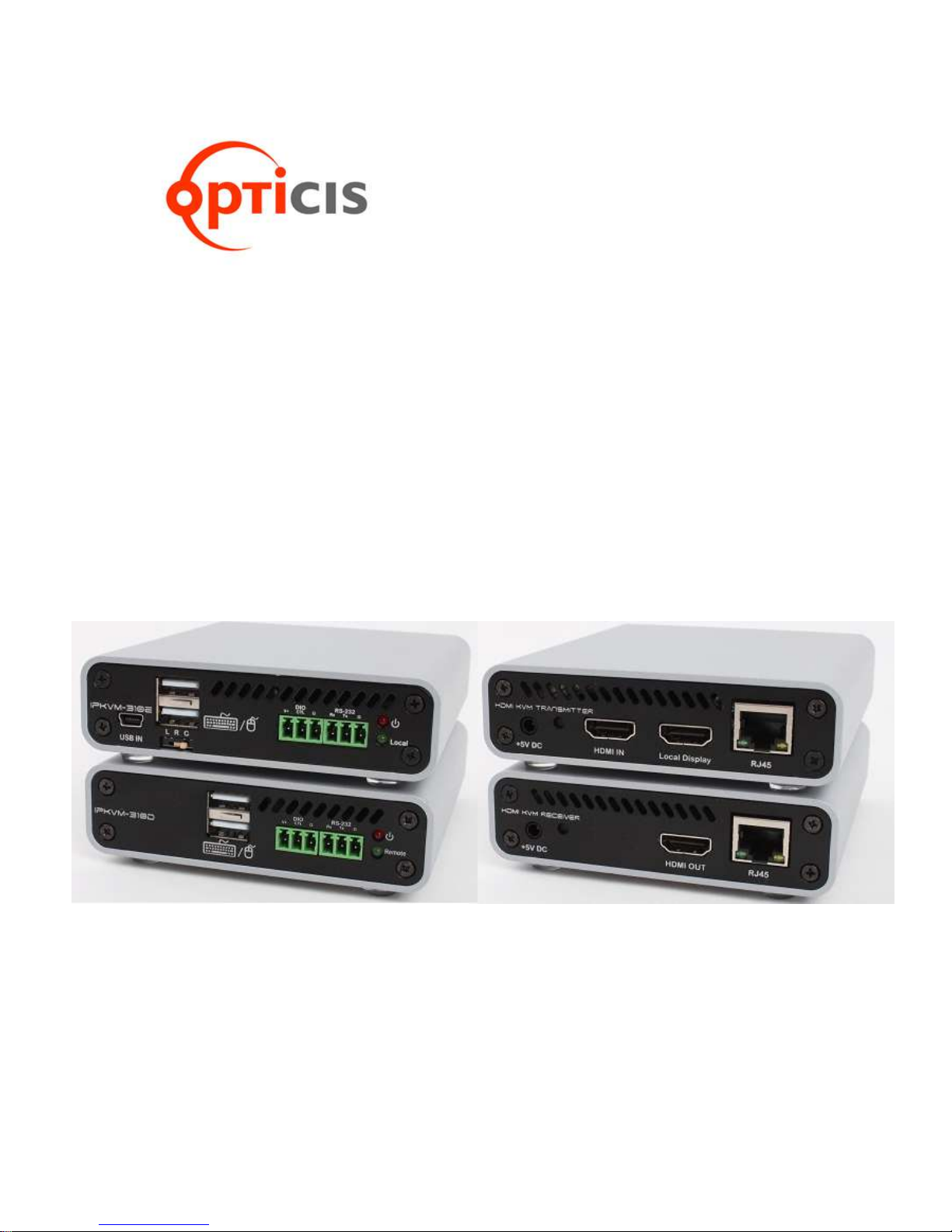
Front
Back
Page 2

- 2 -
Contents
Welcome .................................................................................................................................................. 3
Prodcut Description .................................................................................................................................. 3
Main Features .......................................................................................................................................... 4
Network components ............................................................................................................................... 4
Shipping Group ....................................................................................................................................- 5 -
Supporting video resolutions for Input / Output........................................................................................ 6
Application ................................................................................................................................................ 6
System requirements for setup ................................................................................................................ 6
Installation ................................................................................................................................................ 7
Connection Ports ...................................................................................................................................... 8
Setting Local/Remote Authority.............................................................................................................. 11
LED Indication ........................................................................................................................................ 11
SW & Factory Reset ............................................................................................................................... 12
Configuration & Operation...................................................................................................................... 12
RemoteManager (PC Program) ............................................................................................................. 13
Getting Started ....................................................................................................................................... 27
Product Specifications ............................................................................................................................ 32
Externally Setting Local/Remote Authority ............................................................................................. 33
Troubleshooting ................................................................................................................................ - 35 -
Warranty Information ........................................................................................................................ - 36 -
FCC/CE Statement .......................................................................................................................... - 37 -
Page 3
- 3 -
Welcome
Congratulations on your purchase of the IPKVM HDMI / DVI Extender, IPKVM-310ED. This manual
contains information that will assist you in installing and operating the product.
Product Description
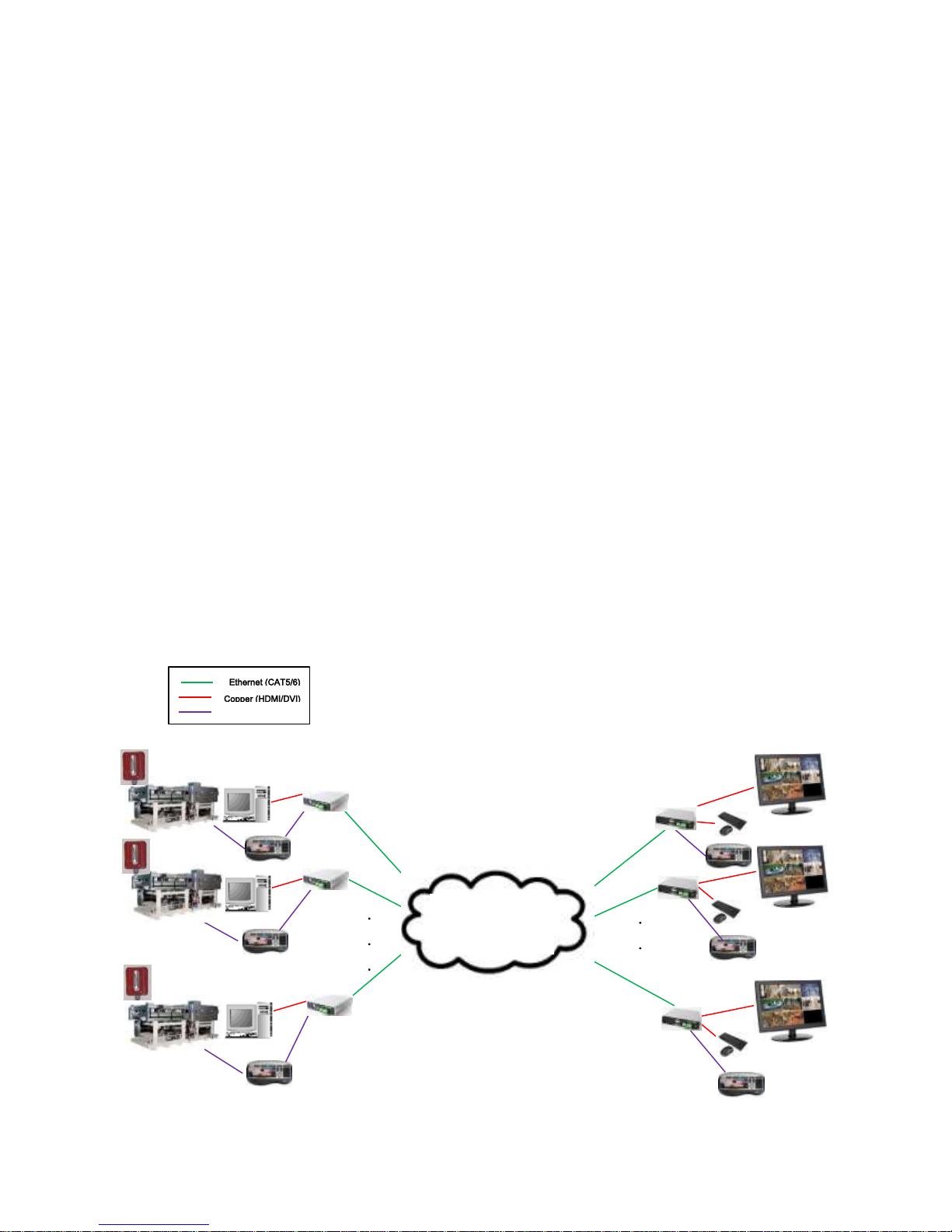
The IPKVM Extender, IPKVM-310ED is designed for extending of HDMI video, keyboard and mouse.
IPKVM-310ED, composed of pairs of transmitters and receivers, works in conjunction to provide
unicast (1 to 1) or multicast (16 to 16) streaming over an IP network. The transmitter, IPKVM-310E
(Encoder), connected to a HDMI PC source, encodes the video signal by H.264 and transmits the
video signal via Ethernet. The receiver, IPKVM-310D (Decoder), connected to a display monitor,
receives the H.264 encoded video signal via the Ethernet and decodes video signal for HDMI display.
The USB keyboard and mouse interface in the remote receiver, IPKVM-310D, also can be accessed
to the source via transmitter IPKVM-310E, if it is connected to the source by USB interface.
The IPKVM-310-ED supports the digital video data of full HD up to 1920x1080p at 60Hz and stereo
audio and transmits the signal via Internet / Intra network. It also enables to distribute sixteen (16)
video sources up to sixteen (16) displays in the multi-screen mode or the single-screen HD mode on
the remote displays and makes sixteen (16) local keyboard and mouse accesses to the source. By
using GUI interface and PC program, user can control the transmitters for connecting in the receiver
side. With these key features, 16 x 16 IP routing system can be configured.
Copper (RS232)
.
.
RX#1
RX#2
RX#N
.
.
.
TX#1
TX#2
TX#M
Monitor
Local Site
Intra Network
Via Ethernet
Knob Decoder
(Local Knob)
RS232
Knob Encoder
(Remote Knob)
RS232
Remote Site
Instrument
Source PC
Page 4

- 4 -
Main Features
♦ LAN standard: 802.3 Ethernet 10/100Mbps (TBD)
♦ Video Resolution: up to 1920x1080p@60Hz
♦ Monitoring Mode: 640x480, 16CH Multi-screen
♦ HID KVM mode: 1920x1080, 1CH Single-screen with HID Keyboard/Mouse
♦ H.264 CODEC
♦ OSD GUI, Multi-screen mode / Single-screen HD mode supported
♦ Remote Manager: PC Program for User Setting & Control
♦ HDMI V1.3, DVI 1.0
♦ USB KVM via backchannel: USB HID mouse & keyboard on remote site or local site
♦ IPKVM-310E(Transmitter,Tx): Power Jack, RJ45, HDMI Input /HDMI Output (Loop-through)
and mini USB port/Dual USB port
♦ IPKVM-310D (Receiver,Rx): Power Jack, RJ45, HDMI Output and Dual USB ports
Network components
♦ Source: A video source connected to a transmitter (encoder), a source can be a media player,
personal computer, or camera.
♦ Transmitter (Encoder): An encoder is needed for each source and can broadcast to a single
transmitter (decoder) or to multiple receivers (decoders).
♦ Receiver (Decoder): A decoder is needed for each display output.
Note: A personal computer using a video player such as VLC player can also be used to
decoder the signal from an encoder.
Page 5
- 5 -
♦ PC Controller: Via a PC connected to the network, RemoteManager (PC program) manages
user accounts, configures IP addresses of IPKVM-310EDs and provides user
informations about each IPKVM connection.
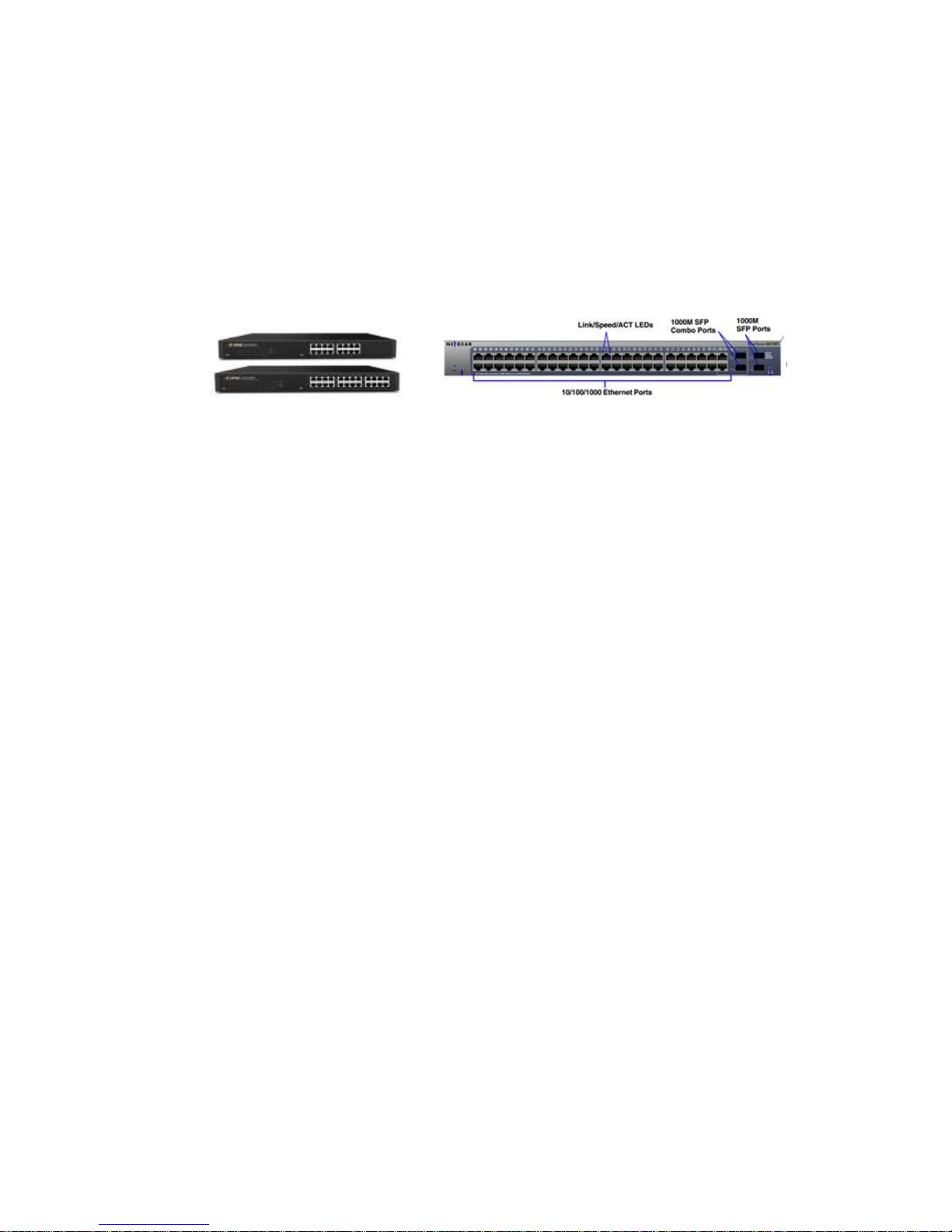
♦ IP Network: An IP network what IP devices is connected via Switching hub.
e.g Ethernet switching hub, Optical-Ethernet switch
Shipping Group
♦ IPKVM-310E: Transmitter (Encoder) or IPKVM-310D: Receiver (Decoder)
♦ AC/DC power adaptor: One (1) unit of 5V, 3A
♦ One (1) HDMI male to male cable (1.5m)
♦ One (1) Mini-USB Cable for PC
♦ User’s manual
Option
♦ Two (2) RS232 cable: DB9 male to 3Pin terminal block
♦ Switch (Tx): Console Switch & RJ11 male to 3Pin terminal block
♦ Indicator(Rx): Console Indicator & RJ11 male to 3Pin terminal block
Page 6

- 6 -
Supporting Video Resolutions for Input / Output (TBD)
IPKVM-310ED supports 3 kinds of resolutions and you have to fix one of them for same EDID. So
a group of Rxs and Txs must have same resolution to display videos of Txs on 16ch multi-screen
of Rxs.
♦ 1280x720p60
♦ 1280x1024p60
♦ 1920x1080p60
Note: Some PC resolutions may not be displayed properly.
Application
♦ KVM
♦ Video Control room
♦ RCS/ROS
Systems Requirements for Setup
♦ Hardware requirements
▶ You must have a HDMI graphic controller or card having a HDMI or DVI port in your PC or
any other equipment being used.
▶ It should support the maximum graphic resolution feature of displays to be connected.
▶ No special requirements for memory size, CPU speed and chipsets, if you’ve already
properly installed your HDMI graphic controllers or cards.
♦ Software requirements
▶ You need to check OS version of your PC or any other equipment being used. [TBD]
♦ Network requirements
▶ You may need Ethernet switch(L2 or L3) as a switching hub, Optical-Ethernet switch or
router for connecting multiple IPKVM -310EDs in Local intranet or Internet. And also it is
possible to communicate directly between one pair of IPKVM-310ED, point-to-point
connection. Network speed of each port of Ethernet switch requires 100/1000Mbps
Page 7

- 7 -
♦ Control PC requirements
▶ We provides a PC program for management and monitoring. The program manages user
accounts, configure IP addresses of IPKVM-310EDs and help user to know about each
IPKVM connection.
▶ Requirements: Windows XP and Window7 (or above OS)
♦ AC/DC Power Adapter Technical Advisory
▶ The IPKVM-310ED has a reverse voltage protection circuit and receiver (Rx) module also
has overcurrent protection circuit.
▶ The IPKVM-310ED is designed to use mainly external +5V AC/DC power adaptor. The
internal power supplied through a HDMI pin (#18) from the graphic source is used to
identify normal connection between a source and transmitter, IPKVM-310E.
Installation
Important: Please keep the installation procedure below. Improper or no operation may result if the
start-up sequence is not followed correctly.
Step 1
Carefully unpack the contents of the shipping group.
Step 2
Turn on the PC, display, and network server
Step 3
Connect HDMI IN port in IPKVM-310-E (Tx) to the PC by supplied HDMI cable.
Step 4
Connect mini USB port in IPKVM-310-E (Tx) to USB port in PC with supplied USB cable.
Step 5
Connect Local Display port in IPKVM-310-E (Tx) to HDMI port in a display with HDMI cable. Then,
Connect the IPKVM-310-E (Tx) to PC over two (2) USB cables for Keyboard and Mouse. You may
skip Step 5 if you don’t need local control.
Step 6
Connect LAN port (RJ45) in IPKVM-310-E (Tx) to LAN port in Network server with LAN cable.
Step 7
Connect HDMI OUT port in IPKVM-310-D (Rx) to a display by supplied HDMI cable.Then, Attach
keyboard and mouse for remote control.
Page 8

- 8 -
Step 8
Connect LAN port (RJ45) in IPKVM-310-D (Rx) to LAN port in Network server with LAN cable.
Step 9
Plug the +5V power adaptors to both IPKVM-310-E (Tx) and IPKVM-310-D (Rx).
Note1: If you change an input source to another source, you have to reset the power of all Txs and
Rxs by re-plging of the +5V power adaptor.
Note2: Please see the page 11 for setting Local / Remote control.
Connection Ports
♦ Connector descriptions
▶ 5V AC/DC Power (Transmitter & Receiver)
Connect the 5V AC/DC Power Adaptor to the connector of each device. When the 5V
AC/DC Power Adaptor is connected to the device, the power LED is turned on. For more
information on LEDs, see “LED indication”
▶ HDMI IN (Transmitter)
Connect your video source (such as a PC) to this connector. If your video source
doesn’t support HDMI output, use an HDMI/DVI cable or an HDMI converter to
connect it to your transmitter device. Note: To connect to this connector, you need a
shielded HDMI cable.
▶ HDMI Out (Receiver)
Connect a digital monitor to this connector. If your digital monitor has not an HDMI
input, use an HDMI/DVI cable or an HDMI adaptor to connect it to your receiver
device. Note: To connect to this connector, you need a shielded HDMI cable.
▶ Local Display (Transmitter)
Connect a digital monitor to the HDMI output connector. If your digital monitor has
not an HDMI input, use an HDMI/DVI cable or an HDMI converter to connect it to
your transmitter device. Note: To connect to this connector, you need a shielded
HDMI cable.
▶ RJ45 (Transmitter & Receiver)
Connect a network cable (CAT5e/CAT6) to this connector.
▶ mini USB port (Transmitter)
Page 9

- 9 -
Connect a source PC to this connector for the purpose of using HID mouse or
Keyboard.
▶ USB A Type (Transmitter and Receiver)
Connect a mouse and/or a keyboard to this connector for the purpose of using HID
mouse or Keyboard.
▶ RS232 (Transmitter & Receiver):
Optional - Connect a RS232 cable to this terminal block for the purpose of using a
knob or controller (which controls an instrument or receive some data from an
instrument).
▶ DIO (Transmitter & Receiver):
Optional - Connect a DIO cable to this terminal block for the purpose of using Knob
or console switch/console indicator (which set and display an Local/Remote
Authority).
Note: If you change a source to another source such as PC, Camcorder, you have to reset
the power of all Txs and Rxs by re-plugging of the +5V power adaptor.
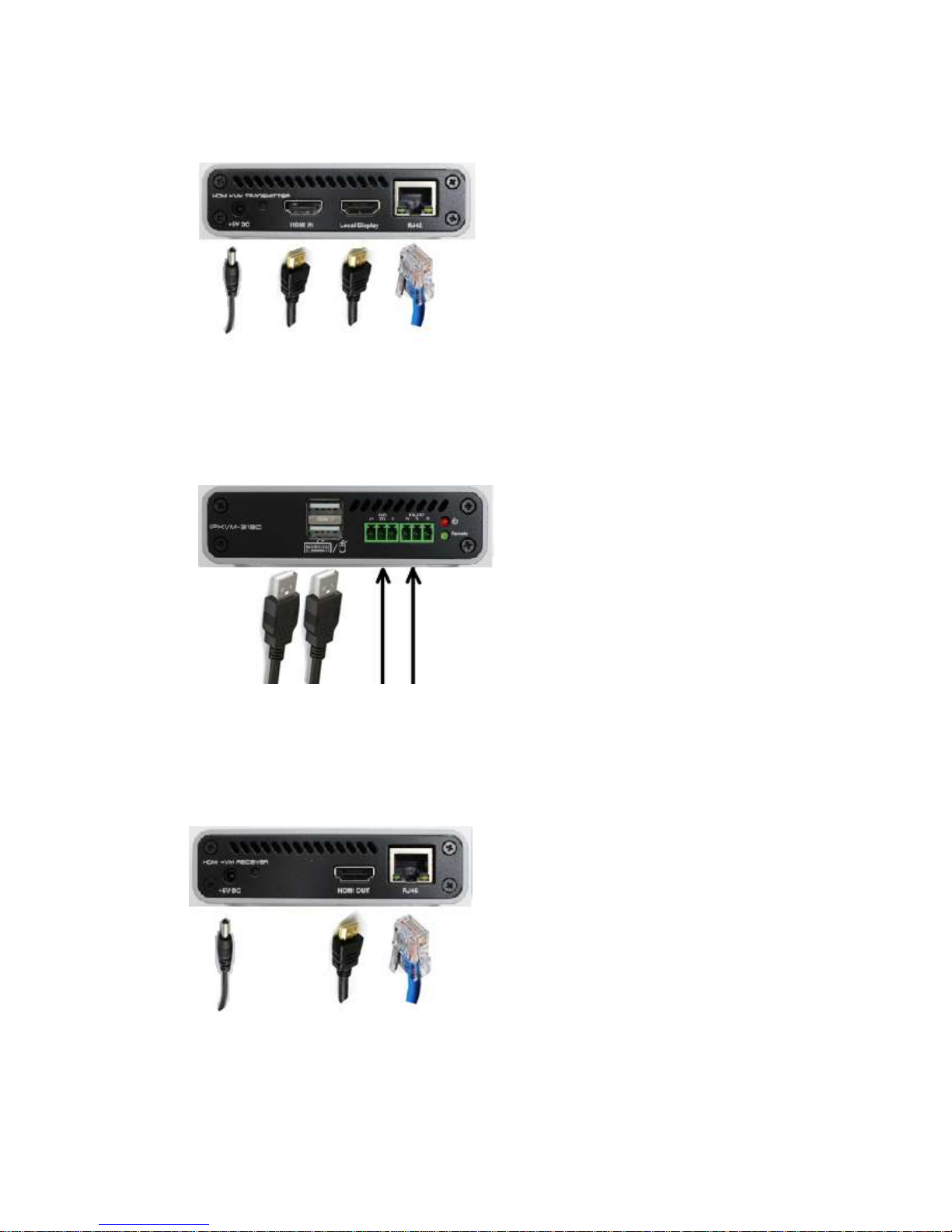
♦ IPKVM-310E Transmitter Front
Mini USB USB A for DIO RS232
for PC Mouse/Keyboard (Terminal Block)
Page 10
- 10 -
♦ IPKVM-310E Transmitter Back
Power Jack HDMI Input HDMI Output RJ45 JACK
(5V, 3.5mm) (Source) (Monitor) (LAN)
♦ IPKVM-310E Receiver front
USB A for DIO RS232
Mouse/Keyboard (Terminal Block)
♦ IPKVM-310E Receiver back
Power Jack HDMI Output RJ45 JACK
(5V, 3.5mm) (Monitor) (LAN)
Page 11
- 11 -
Setting Local/Remote Authority
Note: You can use KVM (including an HID mouse and/or a keyboard, or a knob (or controller)) under
user’s authority. You can access to the devices by a login with user ID and set user’s authority to
Local or Remote state for purpose using Keyboard/Mouse. And you can see whether you can access
the devices on the display of monitors of a remote site.
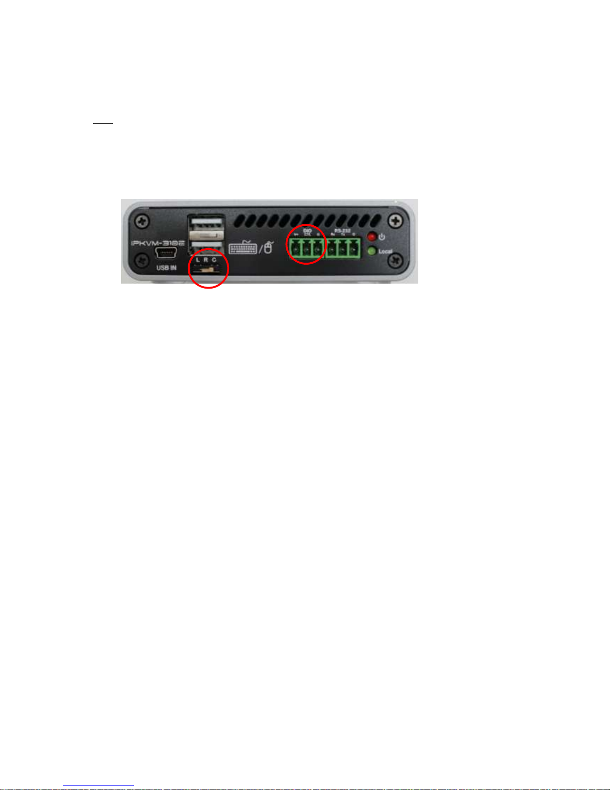
♦ 3-state Slide Switch
You can set user’s authority to Local, Remote, or Console (L/R/C) on the 3-state Slide
Switch. “L” means Local state, “R” means Remote state, and “C” means Console state.
Console State means a state which you can select a Local or Remote state on an external
console switch. (Refer to “A.1 Externally Setting Local/Remote Authority”)
LED Indication
IPKVM-310ED has two (2) LEDs for Power and Authority status located on the front
♦ Power status LED (Red)
When power is applied, the red LED will be turned on.
♦ Authority status LED (Green)
If green LED turns on on the transmitter, IPKVM-310E is ready to use HID Mouse/Keyboard
and others (Knob, etc.) on the Local site. And also if green LED turns on the receiver,
IPKVM-310D is ready to use HID Mouse/Keyboard and others (Knob, etc.) on the Remote
site.
Page 12

- 12 -
You can decide the authority on the 3-state slide switch of IPKVM-310E (Transmitter) among
Local, Remote, or Console. If it set to Console on the 3-state slide switch, you can set the
authority state to Local or Remote on the external console switch. And you can see same
status via LEDs on the Console switch and Console Indicator. (Refer to “A.1 Externally
Setting Local/Remote Authority”)
SW & Factory Reset
♦ SW Reset: Press the Reset switch on the back of devices shortly to reset the default software.
♦ Factory Reset: To recover the Factory setting, press and hold the Reset switch on the
Back of devices until the LED is turned off after blinking approx.10sec.
Configuration & Operation
Note: Please keep the installation procedure below. Improper or no operation may result if the start-up
sequence is not followed correctly.
Important: IPKVM-310ED supports static fixed IP on the network and a default IP is 192.168.0.100 on
the Txs and 192.168.0.200 on the Rxs. And also, Gateway is 192.168.0.1 and Subnet Mask is
255.255.255.0 in both Txs and Rxs. So you need change the IP address to another one ,which you
want, by using PC Program.
Page 13
- 13 -
Remote Manager (PC Program)
1) Installing PC Program
Important: First of all, you should check the IP address and Gateway of the PC which should be
set to the same IP class of the deviices,Txs and Rxs on Network setting of PC.
eg. Tx 192.168. 0.40 (GW 192.168.0.1), Rx 192.168.0.51(GW 192.168.0.1)
=> PC 192.168.0.xxx (GW 192.168.0.1)
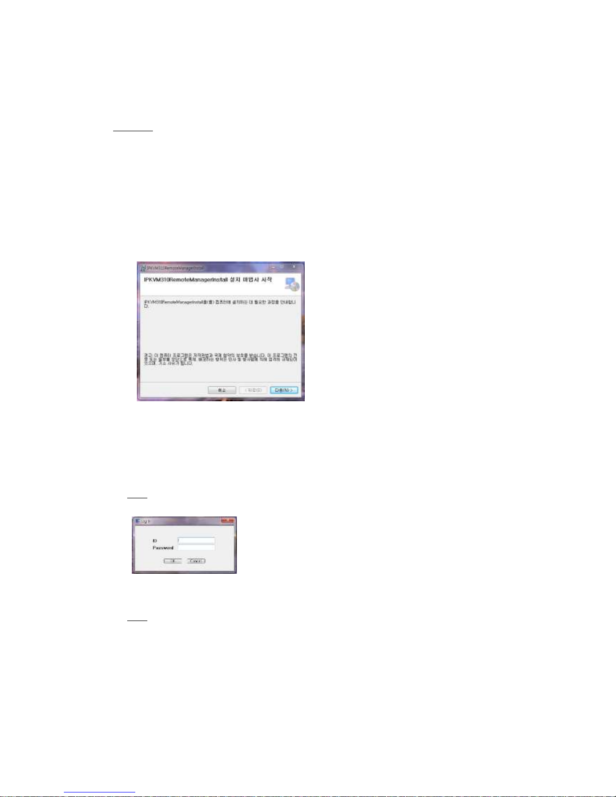
(1) Run the setup.exe on the Window Operating System.
(2) Carry out the procedure according to on-screen instructions.
▶ It will take a few seconds installing procedure to be completed.
(3) Firstly, uninstall on the Control Panel of Window OS to re-install or upgrade the PC Program.
2) Logging in
♦ If installation is completed, you can ready to access the PC program and setup system totally.
(1) Run the PC program (RemoteManager).
(2) Firstly, login as an admin ID & password to access the PC program.
Note. A default value of administrator ID and Password are “admin” and “12345” for logging in.
3) User account
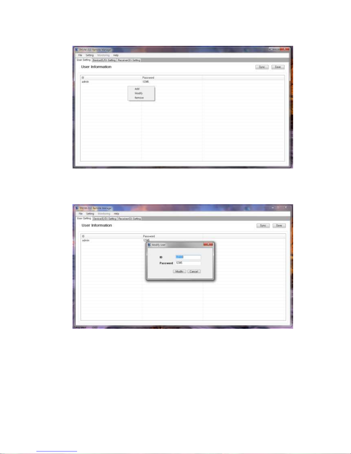
Note. A default administrator ID & password are “admin” and “12345”. You had better modify
the password.
(1) Click Mouse right button to modify the value.
Page 14
- 14 -
(2) Change the value of the password to another one. It is limited to 10 characters including
numbers and English alphabets.
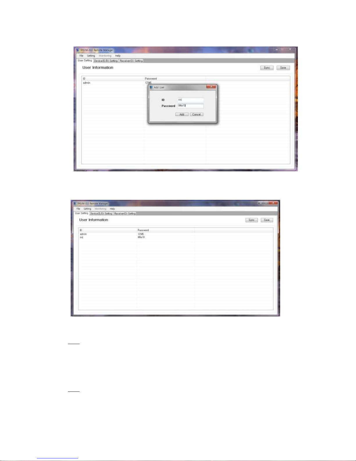
(3) Add user IDs and passwords for general users.
▶ Click Mouse right button to add or modify the values.
▶ It is also limited to 20 characters including numbers and English alphabets.
Page 15
- 15 -
(4) Press “Save” and “Sync” to save and use user accounts
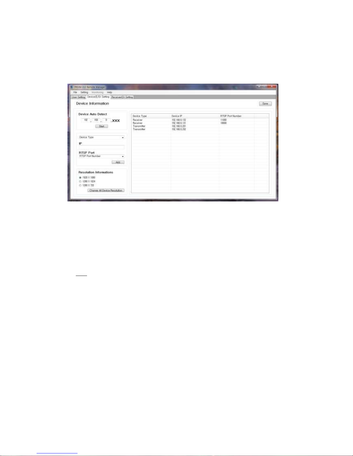
4) Device(E/D) setting: to add, automatically detect and change device information.
Note: You can register the devices such as transmitters (IPKVM-310E encoders) and receivers
(IPKVM-310D decoder) to connect as a group of network connection.
There are two methods:
- You can automatically detect in the network and change devices and register those.
- You can manually add or change devices and register those.
Note: To register the devices to Tx list and use Rx grouping, you shoud press ‘Save’ button to
save the IP list after you add and change the devices.
Page 16
- 16 -
♦ You can automatically detect the devices.
This method is to find devices automatically and register easily if the devices, Txs and Rxs, are
already connected in the network.
(1) Firstly, check and enter IP class to find easily. eg. 192.168.0.xxx
(2) Press “Start” button.
♦ You automatically detected devices so, you can see 4 IP Addresses connected to the
network on the above figure.
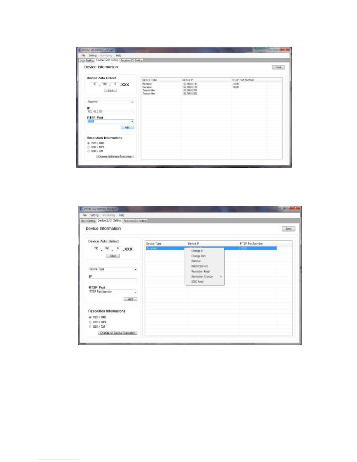
♦ You can rmanually add IP address of a transmitter or a receiver.
Note: Also you can add or change an IP address of each device in the condition of being
directly connected to PC through LAN cable using this same PC program.
(3) Select Device type on the top left corner. : Select one of Transmitter(E) and Receiver(D)
(4) Enter IP address in case of Txs. eg. 192.168.0.41
(5) Or enter IP address and select RTSP port from list(10000~25000) in case of Rxs
eg. 192.168.0.51, and 12000
(6) Press “Add” button to apply the device to the list.
Page 17
- 17 -
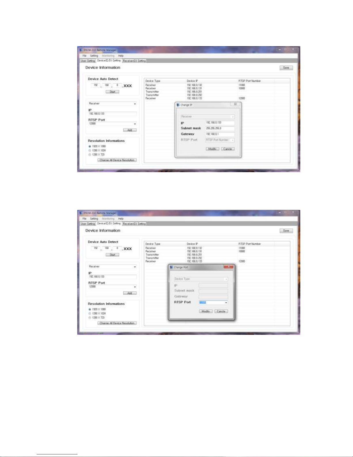
♦ You can change IP address of a transmitter or a receiver.
(7) Click Mouse right button and slect ‘change IP’ to change to another IP address.
Page 18
- 18 -
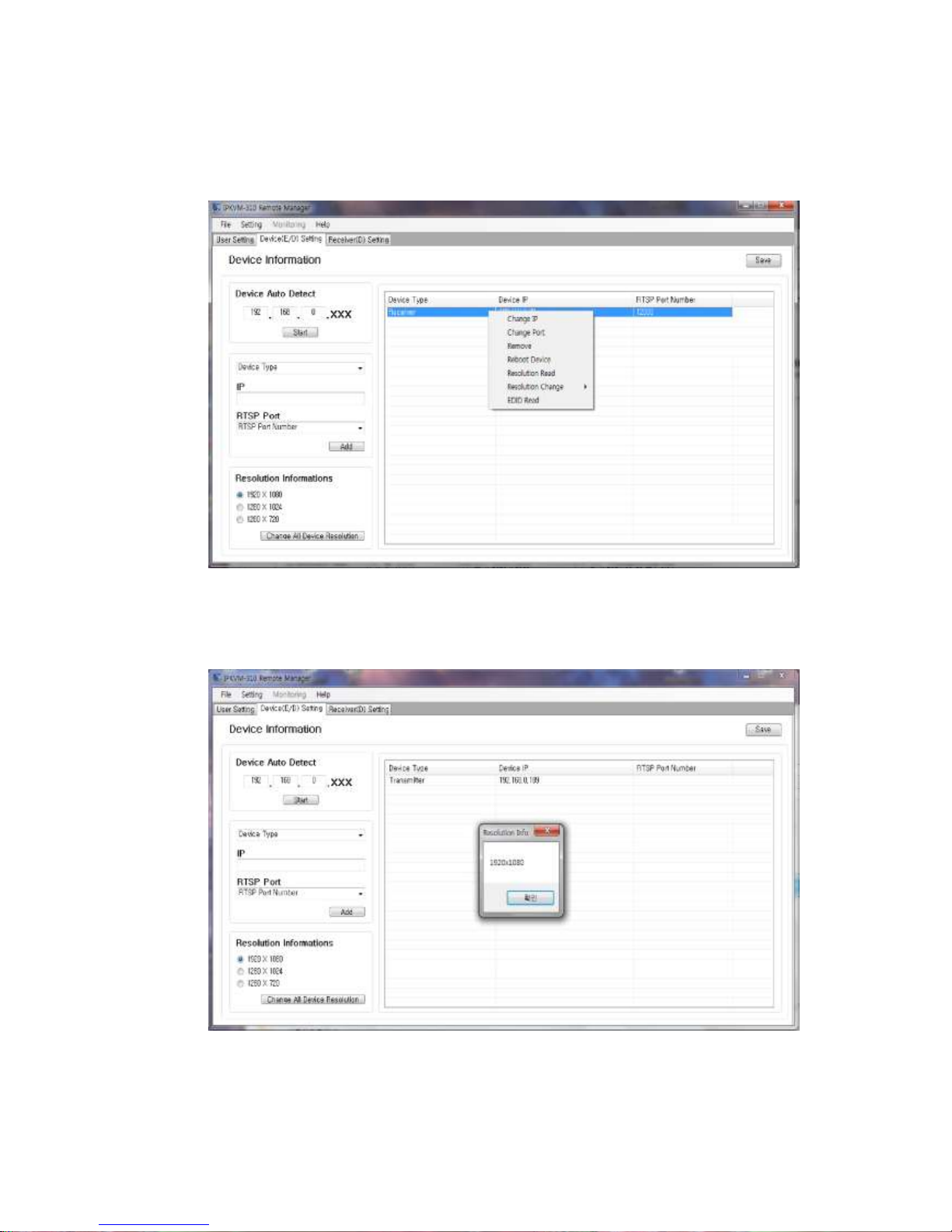
♦ You may change to another port of change IP address in case of Rx device.
(8) Click Mouse right button and slect ‘change port’
Page 19
- 19 -
♦ You can read the current resolution of the device (for your information)
(9) Click Mouse right button and select “resolution read”
(10) You can see the current status about resolution of the device
[both receivers and transmitters]
Page 20
- 20 -
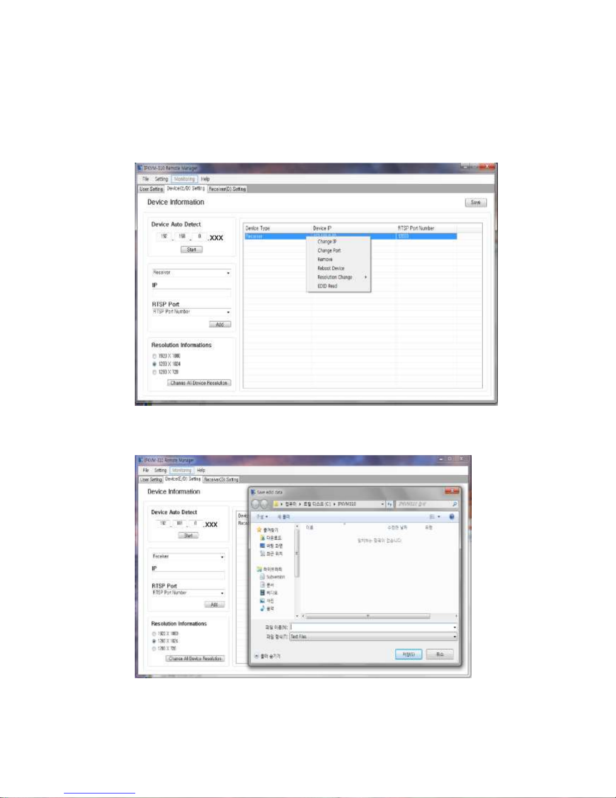
♦ You can read and write the EDID of the connected monitor without using builted-in EDID.
(11) Connect a monitor to HDMI/DVI port of the Receiver and recycle the power supply of
selected device
(12) Click Mouse right button and select “EDID read”
(13) You can read and the EDID of the connected monitor
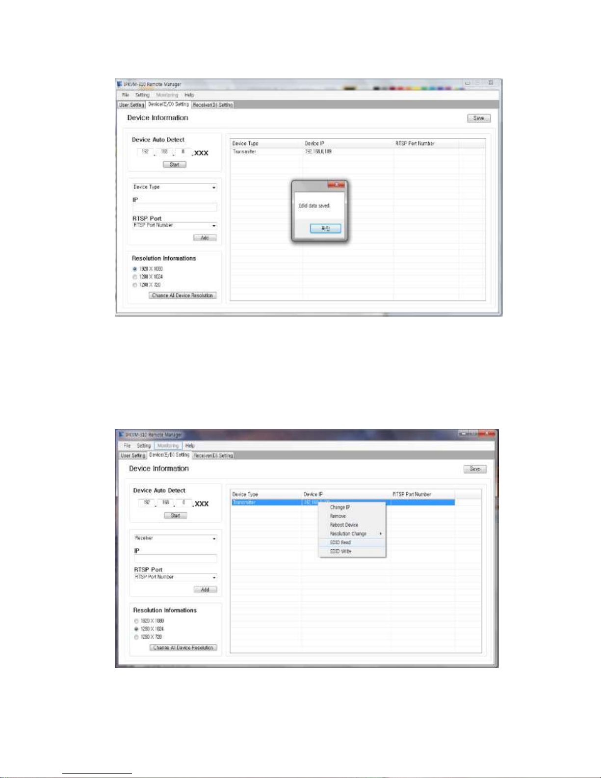
(14) You can save the red EDID to PC for writing the EDID to a transmitter.
Page 21
- 21 -
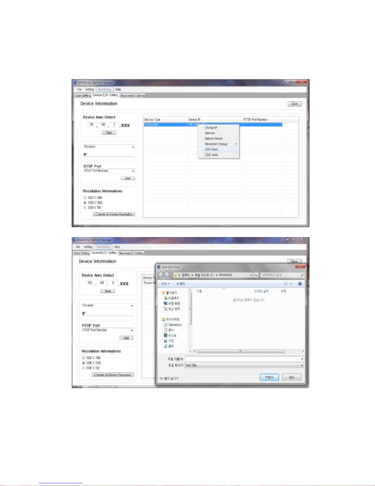
♦ You can repeat [11]~[14] to read EDID of a transmitter except connecting a monitor to
HDMI/DVI Loop-through port of the Transmitter
Page 22
- 22 -
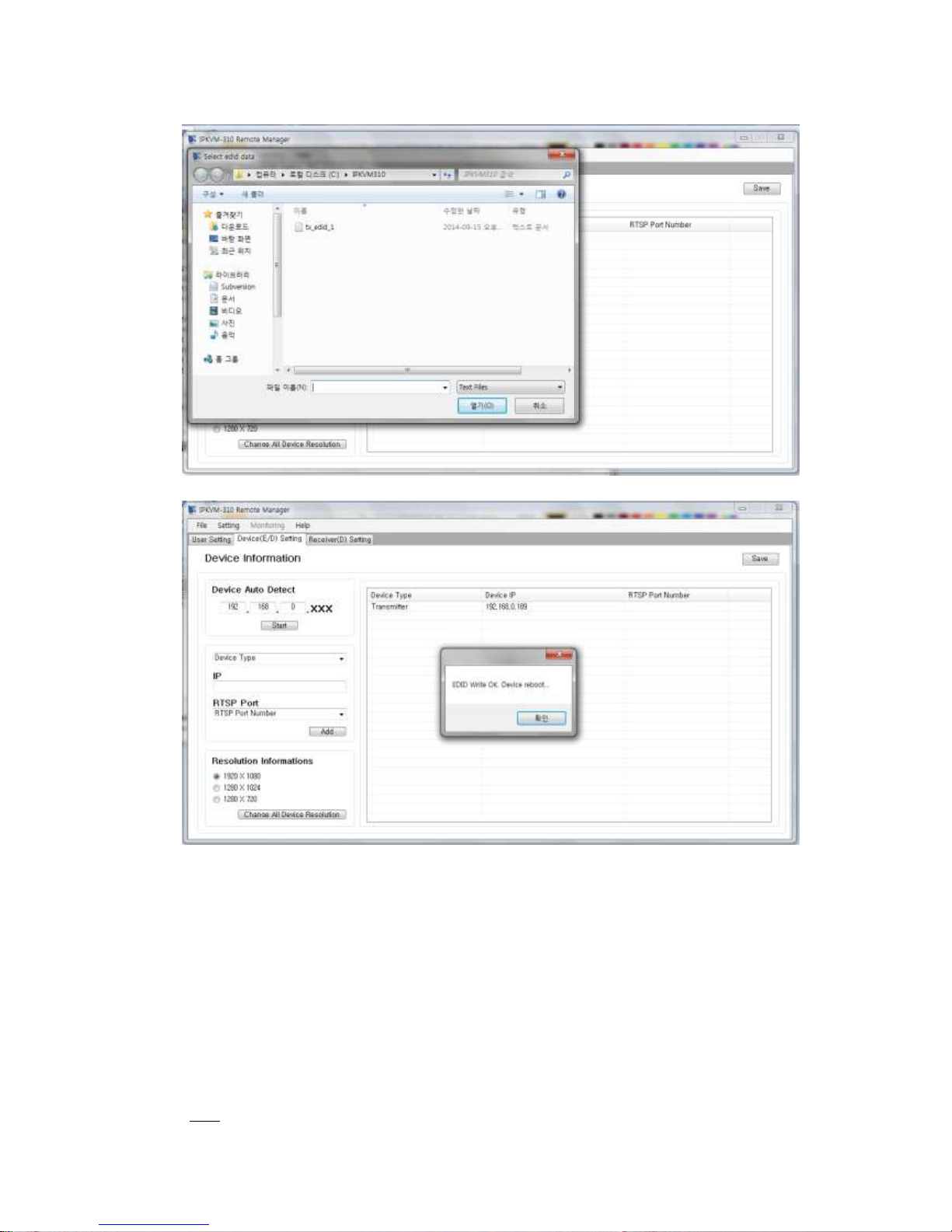
♦ You can write the EDID to the transmitter from previously saved EDID data in PC.
(15) Click Mouse right button and select “EDID write”
(16) Select the EDID to the transmitter from previously saved EDID data in PC.
And then you can see a message ,“EDID write OK, Device reboot”
Page 23
- 23 -
♦ You can reset device to reboot or recycle the power supply of selected device.
(17) Click Mouse right button and select “reset device”
♦ You can select ‘change resolution’ of device individually.
(18) Click Mouse right button and select “resolution change”
♦ You can also change resolution of all devices in the network as one of 1920x1080,
1280x1024, and 1280x720 (TBD) when you need to change the resolution for consideration
of a source or a monitor.
Note: This function apply to all device in the network at a time.
Page 24
- 24 -
(19) Check another resolution and press the button, “Change All device resolution”
Note: In cases of (17),(18) and (19), the devices are rebooted if those fuction is applied.
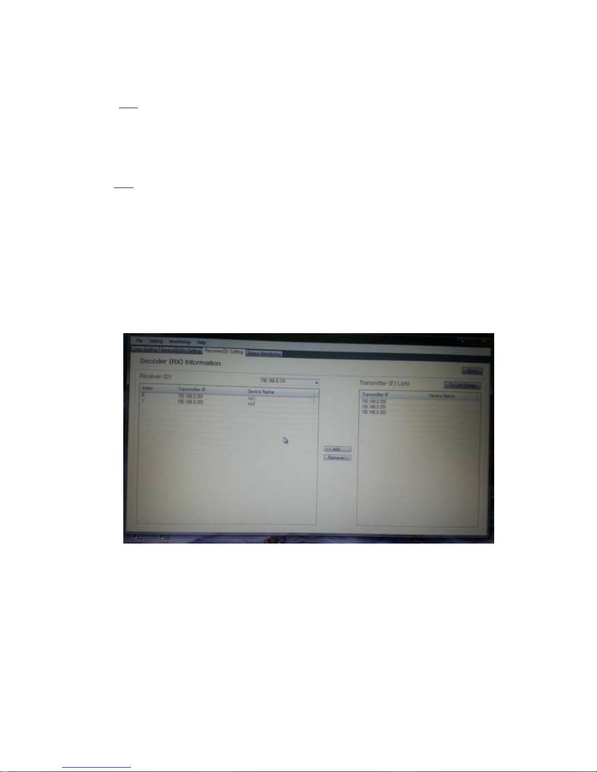
5) Receiver(D) setting
♦ You have to register a group of transmitters up to max. 16 to each receiver.
Note: Before add the Tx IP to the list , firstly insert the name to each transmitter.
♦ You can insert device name to each transmitter by double clicking an area of the device
name (top right). (Eg. No 1 or Hitach16.)
(1) Double click an area of device name
(2) Insert a name to the area of the device name (top right)
(3) Select a receiver (including IP address) from the list of Rxs
(4) Click “Tx List Reload” and add a transmitter from transmitter (E) list.
(5) Or, remove a transmitter from selected transmitters.
(6) Repeat (3)-(4) to add another transmitter.
♦ You can change the order of the transmitters in the group of receiver on the multi-screen.
(7) Double click an area of the index
(8) Change the number and then the number and matched number change all together.
Eg. it changes to Index0 (no. 2) and index1 (no.1) on the above figure.
Page 25
- 25 -
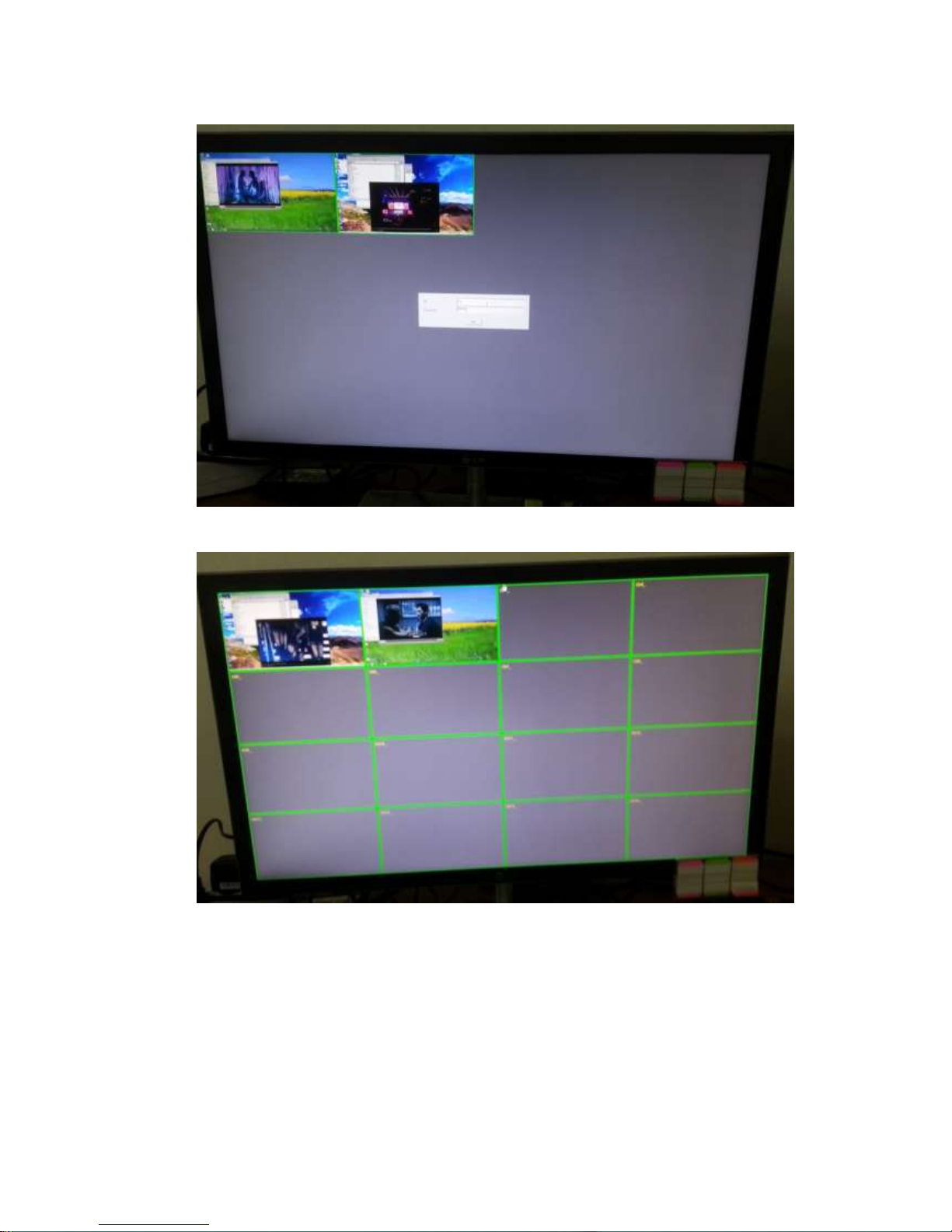
(9) Press “Sync” button to save and use as a group of the list to each receiver.
♦ You can see the device name on each channel after login.
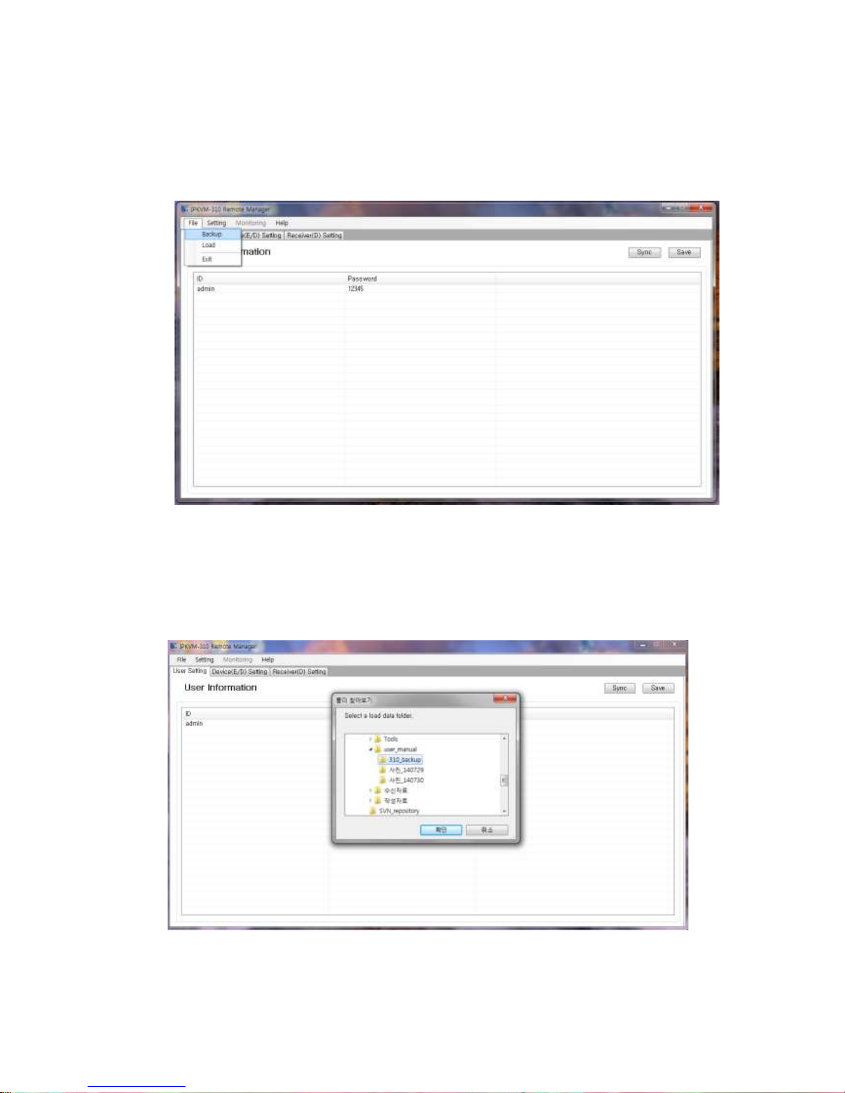
(10) Backup and load of Setup environment which was already set in other PC
You can easily use previous setup environment without complicated steps. So, firstly you need
copy files from previous PC and load the setup environment on new PC.
Page 26
- 26 -
♦ Backup
(1) Select “backup” button on the top menu.
(2) Select a file folder on the PC which you want to backup.
♦ Load
(3) Firstly, copy and paste to the files backed up to a file folder on new PC.
(4) Select “load” from file on the top menu.
(5) Select the file folder on the PC which you backed up the setup environment.
Page 27
- 27 -
Getting started
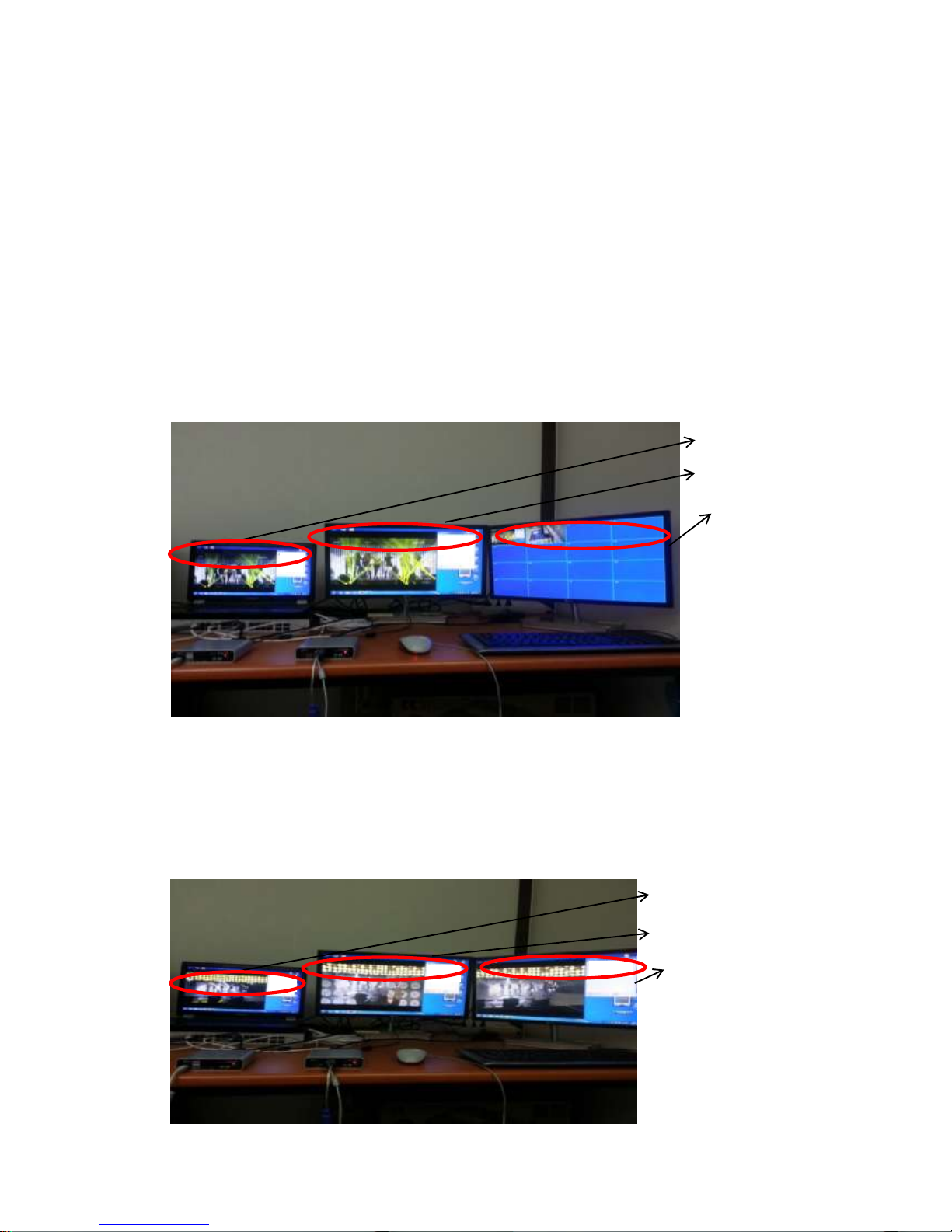
1) How IPKVM-310 works: 16CH multi-screen mode
♦ When 2 pairs of IPKVM-310ED have been connected, it will be totally showed as below.
▶ A Source (PC) is connected to the input port, HDMI IN, of the transmitter (E).
▶ A Local Display monitor is connected to the HDMI output port as a Loop-through port of
the transmitter (E).
▶ A Remote display monitor is connected to the output port, HDMI OUT of the receiver(D)
▶ The Remote display shows as 16CH multi-screen mode.
2) How IPKVM-310 works: 1CH Single-screen HD mode
▶ The Remote display shows as 1CH single-screen HD mode.
Local Display
(Loop-through)
Remote Display
Source (PC)
Local Display
(Loop-through)
Remote Display
Source (PC)
Page 28
- 28 -
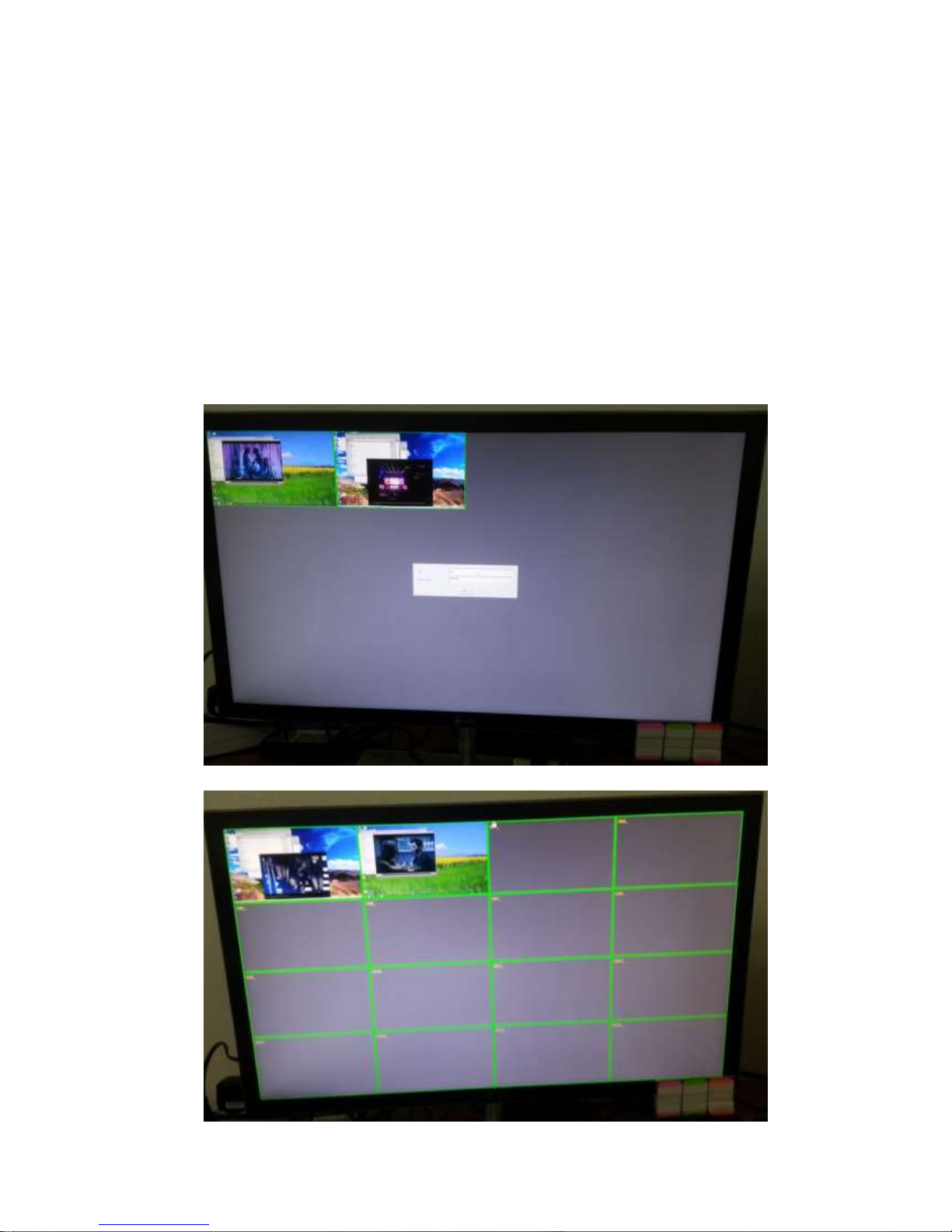
3) Logging in
♦ When multi-pairs of IPKVM-310EDs (e.g 2 or 3 pairs) have been connected, it will be showed
as below.
♦ On the remote (Receiver) site, 2 transmitters have been connected and it shows an initial
view before logging in.
(1) To access the Remote display, first, login with a user ID which is register in PC Program
(RemoteManager).
♦ After finishing work in the remote site, it is available to log out.
(2) Click Mouse right button, and select “logout”
Page 29
- 29 -
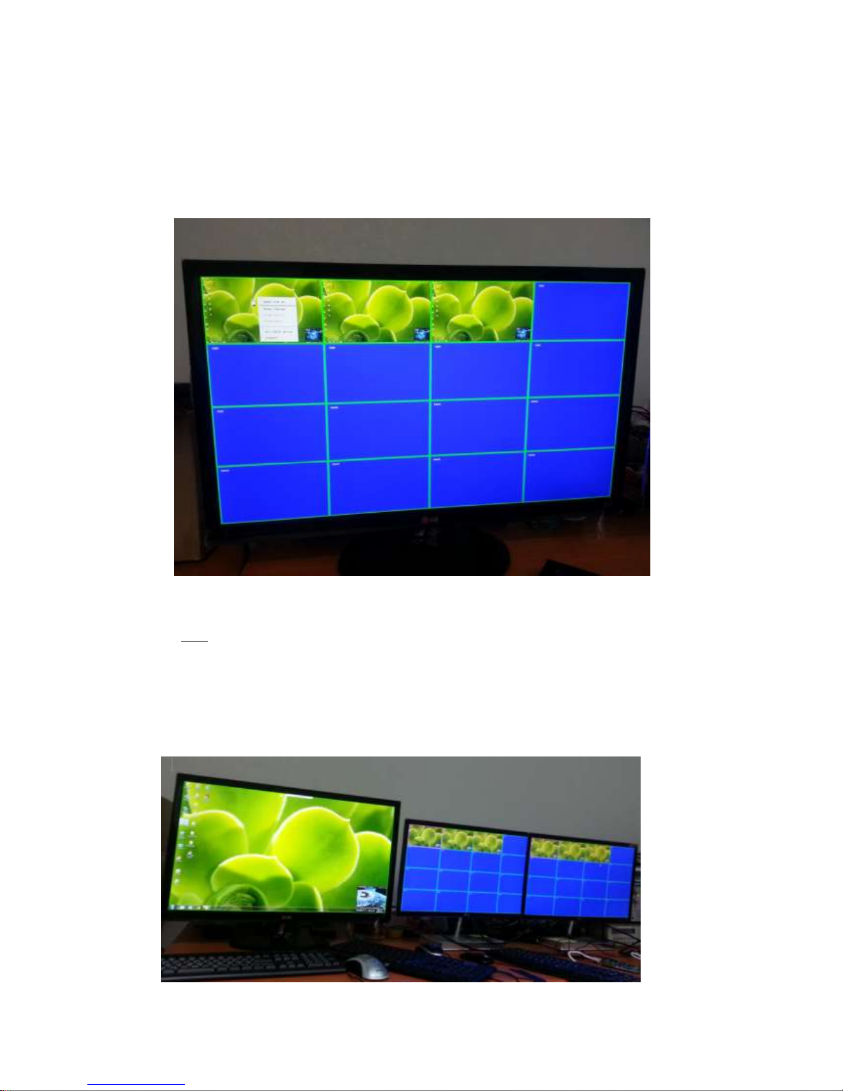
4) Mode Change
(1) To change to 1CH single screen mode, click mouse right button and select “Mode change”
or doble click on selected channel.
♦ You can see on left corner that it operates as HID mode in the 1CH single-screen HD mode.
Note: If you select a transmitter and change it to the single-screen HD mode for using it in
HID KVM mode on a remote (receiver) site, you cannot use the transmitter on other
receivers. So, you can see that the color of the framework of CH1 (No.1 transmitter) is
changed from green to magenta. It let users know that the transmitter is not available for
HID KVM mode.
Page 30
- 30 -
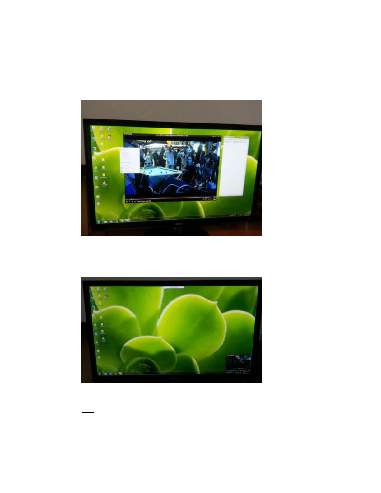
5) HID KVM mode
♦ You can use a keyboard and mouse in the HID KVM mode as below.
▶ You have to use the “Handy point” type mouse as main mouse in the HID mode.
(1) To exit 1CH single-screen mode to 16CH multi-screen mode, move up “Hand type”
mouse and click the “mode change” mark.
♦ You sees that the transmitter return to the 16CH multi-screen mode as below.
Note. You can see that the color of the framework of CH1 (No.1 transmitter) is changed
“Magenta” to “green”.
Page 31
- 31 -
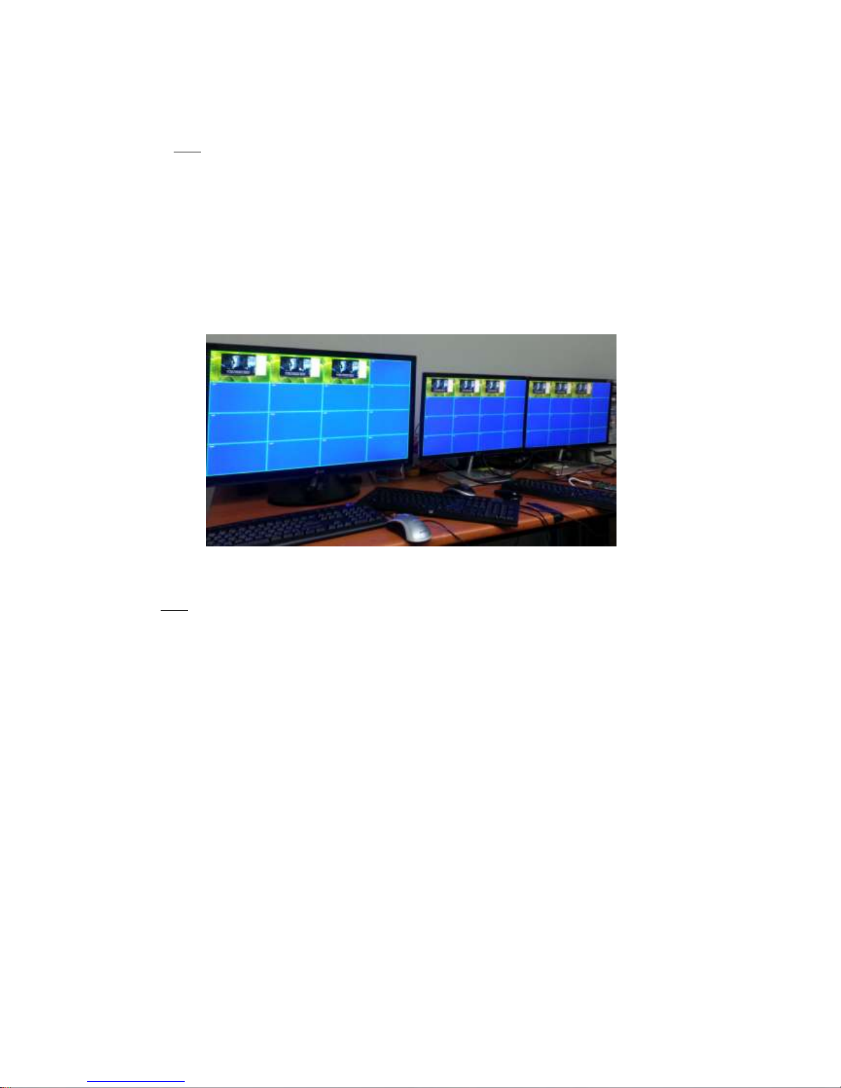
♦ If the color of each framework is green, it says that you can work with the transmitter.
Note.
▶ Green (available): You can work with the transmitter (Source) on the remote (receiver) site.
▶ Magenta (not available): You cannot work with the transmitter (Source) on the remote
(receiver) site.
There are two cases. One is that another user (receiver) uses it in HID KVM mode.
Another case is that the transmitter is worked in Local site. Refer to “Setting Local/Remote
Authority“.
♦ You can insert device name to each transmitter (Eg. No 1 or Hitach16.)
Note: Before add the Tx IP, firstly insert the name to each transmitter.
Refer to 3.4 ([PC] Remote Manager/Receiver Setting)
Page 32

- 32 -
Product Specifications
Item
Description
Display mode
Multi-screen mode(16CH): VGA, 16CH simultaneously Monitoring mode
Single-screen HD mode(1CH):1920x1080, 1CH HID KVM mode
Network(LAN)
10/100 Base-T Ethernet: TCP/IP based wired network with CAT5e/ CAT6 Cables
Video Streaming protocol
RTSP, RTP, RTCP, UDP / TCPIP
Video Codec
MPEG-4 Part 10/AVC (H.264)
Resolution
Up to 1080p@60Hz
Video Interface Standard
HDMI 1.3 and DVI1.0
Tx Video Interface
Input: 1 HDMI/DVI Input
Output: 1 HDMI/DVI Output (Loop-Through )
Rx Video Interface
Output: 1 HDMI/DVI Output
Keyboard/Mouse (Tx)
1x mini USB B type to PC
2x USB A type (for Local HID Keyboard/Mouse)
Keyboard /Mouse (Rx)
2x USB USB A type ( for Remote HID Keyboard/Mouse)
LAN Port
RJ-45 (Tx/Rx 1 port)
RS 232 Port
3 Pin Terminal Block for Knob & alarm interface
Digital I/O Port
Terminal Block for Console Switch & Console Indicator
3 Stage Slide Switch(Tx)
Local/Remote/Console for Control Authority
Reset Switch
SW reset & Factory reset
External Console Switch
(Tx, Optional)
When 3-State Slide Switch set with console, you can select Local/Remote Autority
on the switch pad externally.
External Console Indicator
(Rx, Optional)
When 3-State Slide Switch set with console, you can check Local/Remote Autority
on the pad externally with LED status.
Configuration access
OSD GUI via Mouse/Keyboard
PC Program (RemoteManager) for user account, device setting, status monitoring
EDID
Built-in EDID & EDID Read/Write
Dimension
Tx: 112x28x104mm (WHD), Rx: 112x28x104mm (WHD)
Power
100-240VAC, 50-60Hz
5V 3A Adaptor
Power Consumption (TBD)
Transmitter <10W
Receiver <10W
Operating Temperature
0~50°C
Storage Temperature
-30~70°C
Certification
FCC, CE
Page 33
- 33 -
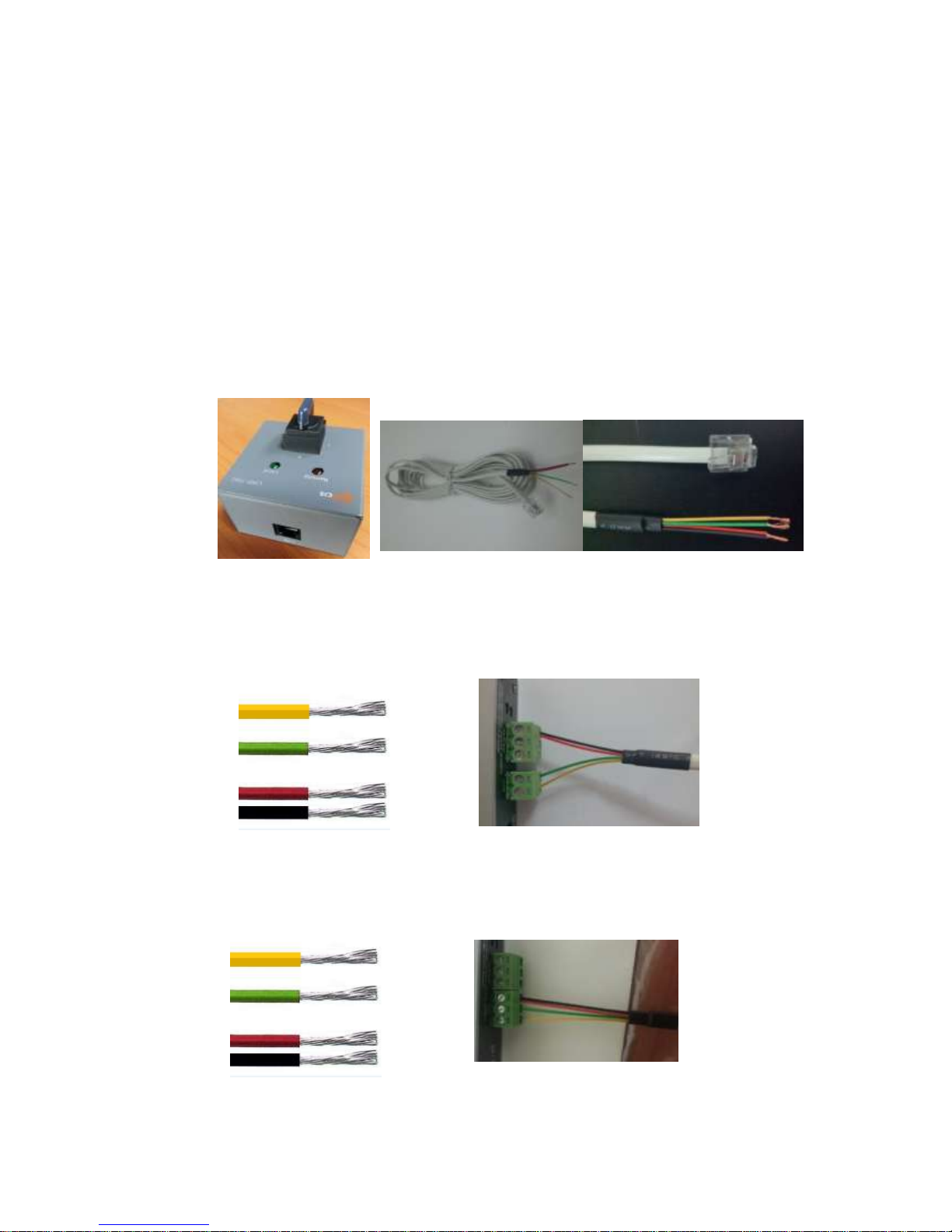
Externally Setting Local/Remote Authority (Option)
♦ Console Switch & Console Indicator
▶ Console Switch (Tx)
The Console switch is to set a Local or Remote state of control authority on an external
switch for user’s convenience. Connect the console switch (left image) to DIO terminal
block of the transmitter device by using a cable (right image). You can set a Local or
Remote state of control authority by rotating the switch and see the state through LED
indication.
1) 2pin Terminal Block
Refer to below figures to know an method and order to 2pin terminal block
2) 3pin Terminal Block
Refer to below figures to know an method and order to 3pin terminal block
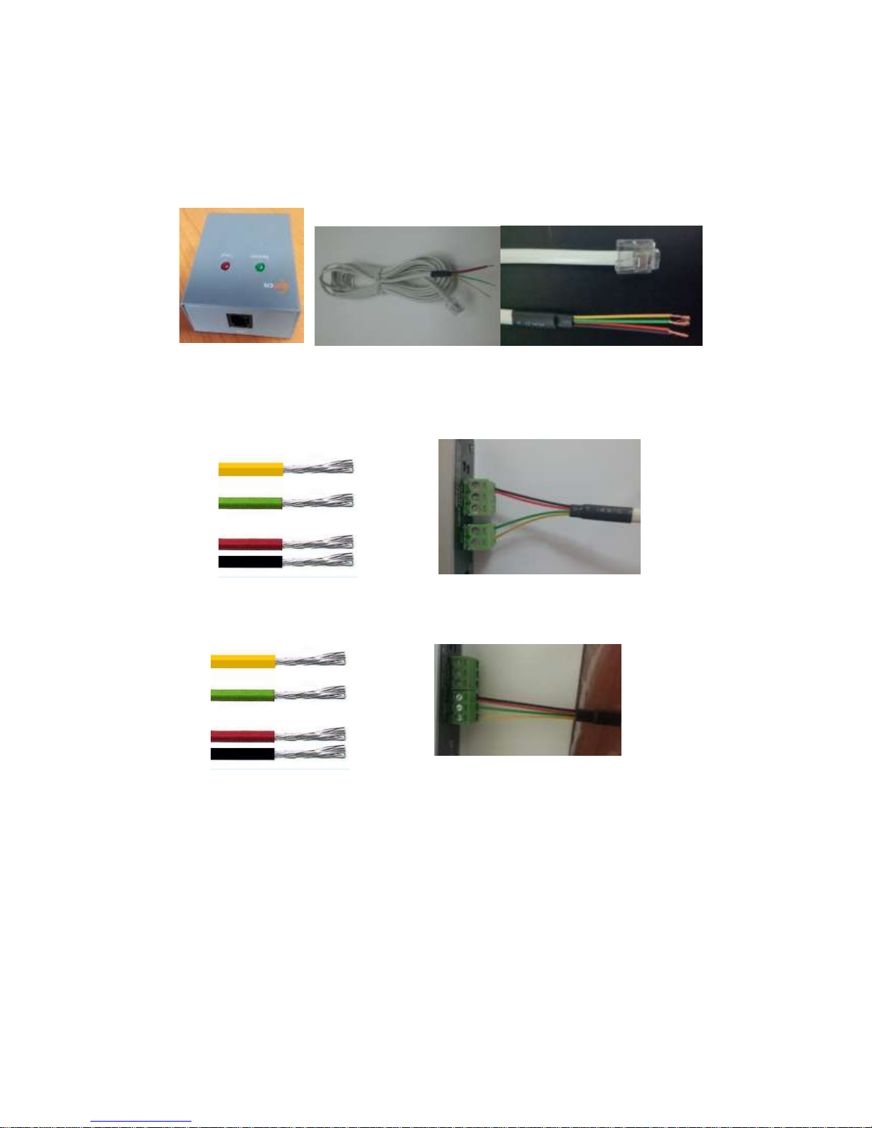
▶ Console Indicator (Receiver)
+3.3V
CTL1
GND
+3.3V
CTL1
GND
Page 34
- 34 -
Connect the console indicator (left image) to DIO terminal block of the reciver device by
using a cable (right image). And then, you can see the Local or Remote state of control
authority through LED indication on the remote site.
1) 2pin Terminal Block
Refer to below figures to know an method and order to 2pin terminal block
3) 3pin Terminal Block
Refer to below figures to know an method and order to 3pin terminal block
+3.3V
CTL1
GND
+3.3V
CTL1
GND
Page 35

- 35 -
Troubleshooting
Problem
Remedy Action
Causes
No video on the display
(16CH multi-screen mode)
- Wait several seconds for the system booting. After the
power is applied, Power status LED will turn on (Red).
- Check the connection of all cables.
- Check the connection of the LAN cable to RJ45
connector
- Check if the graphic resolution of Source PCs is
properly set. Go to the display properties and tap the
settings. Max. Resolution (1920 * 1080 @60Hz)
Cables are
connected
incorrectly.
No video on the display
(1CH single-screen mode)
- Change mode to 16CH multi-screen mode and re-
change to 1CH single-screen mode.
- Reset the power of all Txs and RXs again by re-
plugging the power adaptor or by reboot on the PC
program.
Network
connectivity
issues
Video quality:
- Freezing or collapse
- Mosaic pattern
- Jitter
- Check network connectivity.
- Check if the graphic resolution is properly set. Go to the
display properties and tap the settings.
Max. Resolution (1920 * 1080 @60Hz)
- Reset the power of all Txs and Rxs again by re-
plugging the power adaptor or by reboot on the PC
program.
Network
connectivity
issues
Keyboard or Mouse doesn’t
work properly.
- Ensure the USB cables are connected properly
between Source PC and USB port of a transmitter
- Reset the power of all Txs and Rxs again by re-
plugging the power adaptor or by reboot on the PC
program.
- Change USB cable, if it doesn’t work properly after
reconnecting the cable and reset.-
Cables are
connected
incorrectly.
Abnormal operation occurs in
playing audio/video or USB
Keyboard/Mouse
- Reset the power of all Txs and Rxs again by re-
plugging the power adaptor or by reboot on the PC
program.
After changing input source,
the video clip does not play.
- Execute window media player again.
- Reset the power of all Txs and Rxs again by re-
plugging the power adaptor.
Page 36

- 36 -
Warranty Information
1 (One) Year Warranty
Opticis warrants this IPKVM-310ED HDMI extender to be free from defects in workmanship and
materials, under normal use and service, for a period of
one (1) year from the date of purchase from Opticis or its authorized resellers.
If a product does not work as warranted during the applicable warranty period, Opticis shall, at its
option and expense, repair the defective product or part,
deliver to customer an equivalent product or part to replace the defective itemor refund to customer
the purchase price paid for the defective product.
All products that are replaced will become the property of Opticis.
Replacement products may be new or reconditioned.
Any replaced or repaired product or part has a ninety (90) day warranty or thereminder of the initial
warranty period, whichever is longer.
Opticis shall not be responsible for any software, firmware, information, or memory data of customer
contained in, stored on, or integrated with any products returned to Opticis for repair under warranty
or not.
Warranty Limitation and Exclusion
Opticis shall have no further obligation under the foregoing limited warranty if the product has been
damaged due to abuse, misuse, neglect, accident, unusual physical or electrical stress, unauthorized
modifications, tampering, alterations, or service other than by Opticis or its authorized agents, causes
Page 37

- 37 -
other than from ordinary use or failure to properly use the product in the application for which said
product is intended.
Dispose of Old Electrical & Electronic Equipment
(Applicable in the European Union and other European countries with separate systems)
This symbol on the product or on its packaging indicates that this product shall not be
treated as household waste. Instead it shall be handed over to the applicable
collection point for the recycling of electrical and electronic equipment. By ensuring
this product is disposed of correctly, you will help prevent potential negative
consequences for the environment and human health, which could otherwise be
caused by inappropriate waste handling of this product.
The recycling of materials will help to conserve natural resources. For more detailed information about
recycling of this product, please contact your local city office, your household waste disposal service
or the shop where you purchased the product.
FCC/CE Statement
This device complies with part 15 of FCC Rules and EN 55022/55024/61000-3 for CE certification.
Operation is subject to the following two conditions: (1) this device may not cause harmful
interference, and (2) this device must accept any interference received, including interference that
may cause undesired operation. This equipment has been tested and found to comply with the limits
for a Class A digital device, pursuant to part 15 and 2 of FCC Rules and EN 55022/55024/61000-3 for
CE certification. These limits are designed to provide reasonable protection against harmful
interference when the equipment is operated in a residential installation. This equipment generates,
uses, and can radiate radio frequency energy and. if not installed and used in accordance with the
instruction guide, may cause harmful interference to radio communications. However, there is no
Page 38

- 38 -
guarantee that interference will not occur in a particular installation. If this equipment does cause
harmful interference to radio or television reception, which can be determined by turning the
equipment off and on, the user is encouraged to try to correct the interference by one or more of the
following measures:
♦ Re-orient or relocate the receiving antenna.
♦ Increase the separation between the equipment and the receiver.
♦ Connect the equipment into an outlet on a circuit different from that to which the receiver is
connected.
♦ Consult a service representative for help.
Properly shielded and grounded cables and connectors must be used in order to comply with FCC/CE
emission limits. Changes or modifications not expressly approved by the party responsible for
compliance could void the user s authority to operate the equipment.
Page 39

- 39 -
For order support, please contact your Distributor or Reseller.
For technical support, visit Opticis web site, www.opticis.com or contact [email protected]
Opticis Locations
HQ
16Fl. Kins Tower, 8 Seongnam-daero, 331 beon-gil,
Bundang-gu,
Seongnam-si, Gyeonggi-o, 463-844
Rep. of KOREA
Tel: +82 (31) 719-8033
Fax: +82 (31) 719-8032
Factory
#501 Byoksan Technopia, 560,
Dunchon-daero,
Jungwon-gu,
Seongnam-si,Gyeonggi-do, 462-716
Rep. of KOREA
Tel: +82 (31) 737-8033
Fax: +82 (31) 737-8039
 Loading...