

Page 1
Manual Contents
__________________________________________
Manual Contents 1-0
Welcome! Product Description 1-1
System Requirements for Setup 1-2
Installation 1-3
Self-EDID Programming Procedure 1-5
Troubleshooting, Maintenance, Technical Support 1-6
Product Specifications 1-7
Warranty Information 1-9
Warning for Medical Usage 1-10
UL/EN Statement 1-11
Guidance and Manufacturer’s Declaration 1-12
Pictorials
Figure 1 – Connection Diagram of Optical DVI
Extension Modules 1-1
Figure 2 – Connection of power adapter to the
transmitter and receiver 1-3
Figure 3 – Connection of optical fiber 1-3
Figure 4 – Connection of the transmitter to DVI source
and receiver to the display 1-4
Figure 5 – Connection diagram using optical splitter 1-4
Figure 6 – Position of EDID-PRG. Button and
Status LED 1-5
1-0 Manual Contents
User’s Manual
Doc No. : OE-D150102-12 / Rev1.6
1-Fiber Detachable DVI
module, DVFX-110
www.opticis.com
Page 2
System Requirements for Setup
Hardware requirements
You have to have a DVI graphic controller or card having a DVI
port in your PC, SUN or Mac systems. It should support the
maximum graphic resolution feature of displays to be connected.
No special requirements for memory size, CPU speed and
chipsets, if you’ve already properly installed your DVI graphic
controllers or cards.
Software requirements
No special restrictions, if you’ve already properly installed your
DVI graphic controller in your OS.
AC/DC Power Adapter Technical Advisory
The transmitter (Tx) module of DVFX-110-TR is designed for power
protection circuit from conflict of power supply between the external
AC/DC power adapter and your DVI source by #14 pin.
We strongly recommend to use external AC/DC adapter for
Transmitter (Tx) for stable power supplying. In case of Receiver (Rx),
power should be supplied by AC/DC adapter due to no internal power
supplying from the displays.
1-2 System Requirements for Setup
Welcome!
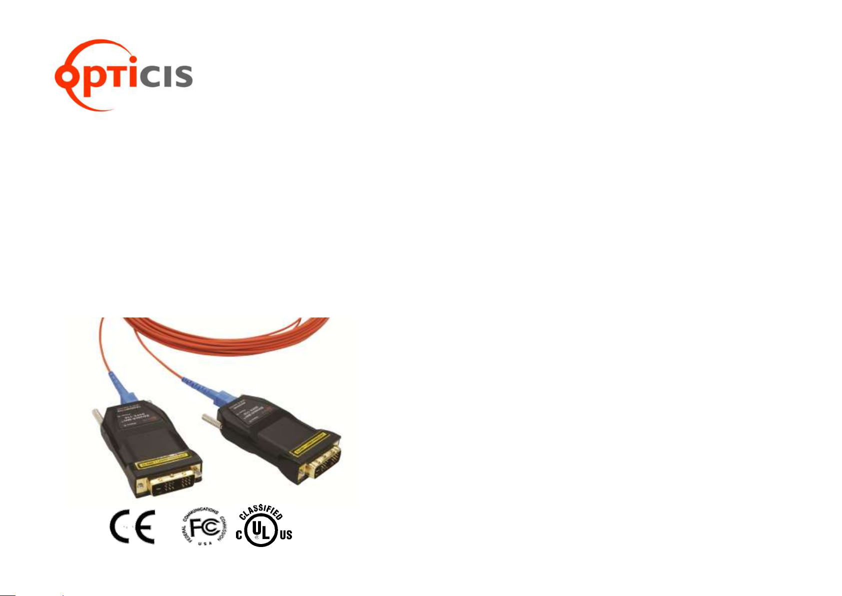
Congratulations on your purchase of the Stretch DVITM DVFX-110-TR
Optical DVI (Digital Visual Interface) Extension Module. This manual contains
information that will assist you in installing and operating the product.
Product Description
The DVFX-110-TR optical DVI module transmits four (4) optical data, Red,
Green, Blue and clock and can be extended up to 1km (3,280ft) over one (1)
SC single or 500meters (1,640ft) over multi-mode fiber at WUXGA
(1920x1200), 60Hz vertical refresh rate. The EDID (Extended Display
Identification Data) in a display can be read and restored by just plugging once
transmitter to the display. This Self-EDID programming feature makes the
installation of DVFX-110-TR more easy and flexile at any variable resolution
display systems. The key features of DVFX-110-TR is, by using an optical
splitter (OPS-116S), one (1) signal from transmitter can be copied up to
sixteen (16) times and it gives you a cost effective and space saving
installation for various application. For your convenience, UXGA EDID would
have been done before shipment as a default.
Shipping Group
DVFX-110-TR Optical DVI Extension Module: One (1) pair
AC/DC power adapter: Two (2) units of +5V, 2A
User’s Manual
Option Product: Simplex SC Patch Cord (Single or Multi-mode fiber)
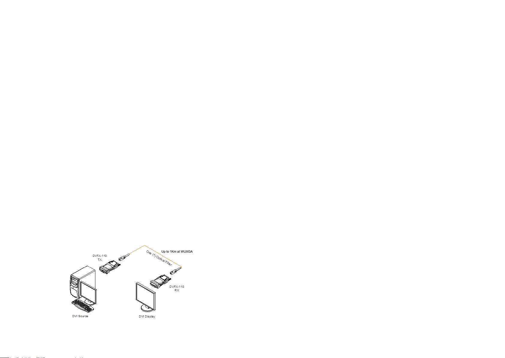
Figure 1 – Connection Diagram of Optical DVI Extension Module
1-1 Welcome, Product Description
Page 3
Installation
Important: Please keep the installation procedure below. Improper or no
operation may result if the start-up sequence is not correctly followed.
Step 1
Carefully unpack the contents of the shipping group.
Step 2
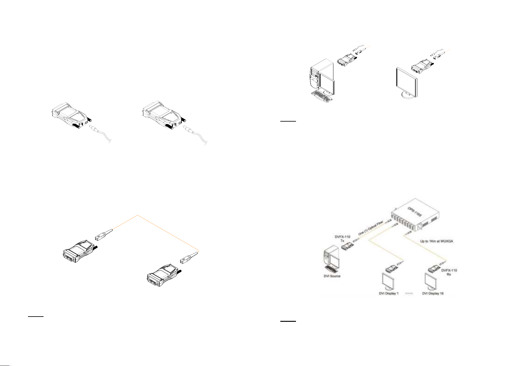
Plug the 5V power adapters to the power jack of the transmitter and receiver.
Ensure the Power LED ON (Green) and Status LED blinking slowly (Green).
Figure 2 – Connection of power adapter to the transmitter and receiver
Step 3
Please, check if the maximum resolution of the display is UXGA (1600x1200).
Otherwise, follow the instructions for Self-EDID Programming Procedure on
page 1-5.
Step 4
Connect SC optical fiber between the transmitter and the receiver as shown in
figure 3.
Figure 3 – Connection of optical fiber
Note: Both single and multi-mode fibers are applicable to DVFX-110-TR. The
maximum extension length by single mode fiber is 1,000meters and
500meters by multi-mode.
1-3 Installation
DVFX-110
Transmitter
DVFX-110
Receiver
One (1) Optical Fiber
Step 5
Plug the transmitter to the DVI receptacle of the DVI source such as PC and the
receiver to the DVI receptacle of the display.
Figure 4 – Connection of the transmitter to the DVI source and receiver to the display
Note: Be recommended NOT to use any intermediate cable or adapter between
them to avoid undesirable performance degradation.
Step 6
Make the PC and the display power ON. And ensure that the Status LED in
transmitter and receiver turn on.
By using an optical splitter OPS-xyz, one (1) signal from DVFX-110 transmitter
can be copied up to sixteen (16) times as shown in figure 5. For more
information, please refer to user’s manual of OPSR-2, OPX-xyz.
Figure 5 – Connection diagram using optical splitter, OPS-104S
Note: The maximum extension length can be shortened by using optical splitter
and additional fibers. The single-mode fiber is only applicable to OPS-xyz.
1-4 Installation (Continued)
DVI Source
DVFX-110
Transmitter
DVI Display
DVFX-110
Receiver
Page 4
Troubleshooting
The display shows only black screen.
- Ensure that all plugs and jacks used by external power supplies (both
Opticis and others) are firmly connected. Ensure that the Power and status
LED ON.
- Ensure that the DVI ports are firmly plugged in to the PC and display.
- Ensure that the transmitter and receiver modules plugged correctly to the
PC and display, respectively.
- Check if the PC and display are powered on and properly booted.
- Reset the system by de-plugging and re-plugging the transmitter DVI port or
receiver DVI port, or by de-plugging and re-plugging the power plugs of
transmitter and receiver modules.
- Re-boot up the system while connecting the optical DVI extension module.
Screen is distorted or displays noises.
- Check if the graphic resolution is properly set. Go to the display properties of
Windows and tap the settings.
- Ensure that the resolution sets less than WUXGA (1920x1200) at 60Hz
refresh ratio.
- Reset the system. Disconnect and reconnect the optical DVI cables or 5V
power adapters.
Maintenance
No special maintenance is required for the optical DVI module and power
adapters. Ensure that the DVI modules and power adapters are stored or
used in a benign environment free from liquid or dirt contamination.
There are no user serviceable parts. Refer all service and repair issues to
Opticis.
Technical Support and Service
For commercial or general product support, contact your reseller. For
technical service, contact Opticis by email [email protected] or visit its
website at www.opticis.com
1-6 Troubleshooting, Maintenance, Technical Support
Self-EDID Programming Procedure
The graphic source equipment generally requires display information (EDID). It contains
resolution and timing information of the display.
DVFX-110-TR supports Self-EDID programming. It is the procedure that reads the EDID from
the display and stores it in the EEPROM of the transmitter. You have to do Self-EDID
programming if the maximum resolution of the user’s display is not UXGA (1600x1200). Follow
the steps below to do it correctly.
Note1: If you know that EDID is not required by the user’s DVI source, Self-EDID
programming is not necessary.
Note2: The default EDID in factory ship-out is programmed in the VESA standard of
UXGA (1600x1200), 60Hz.
Step 1
Power on the display.
Step 2
Plug the 5V power adapter to the power jack of the transmitter of DVFX-110. Ensure
the Power LED ON and Status LED blinking slowly.
Step 3
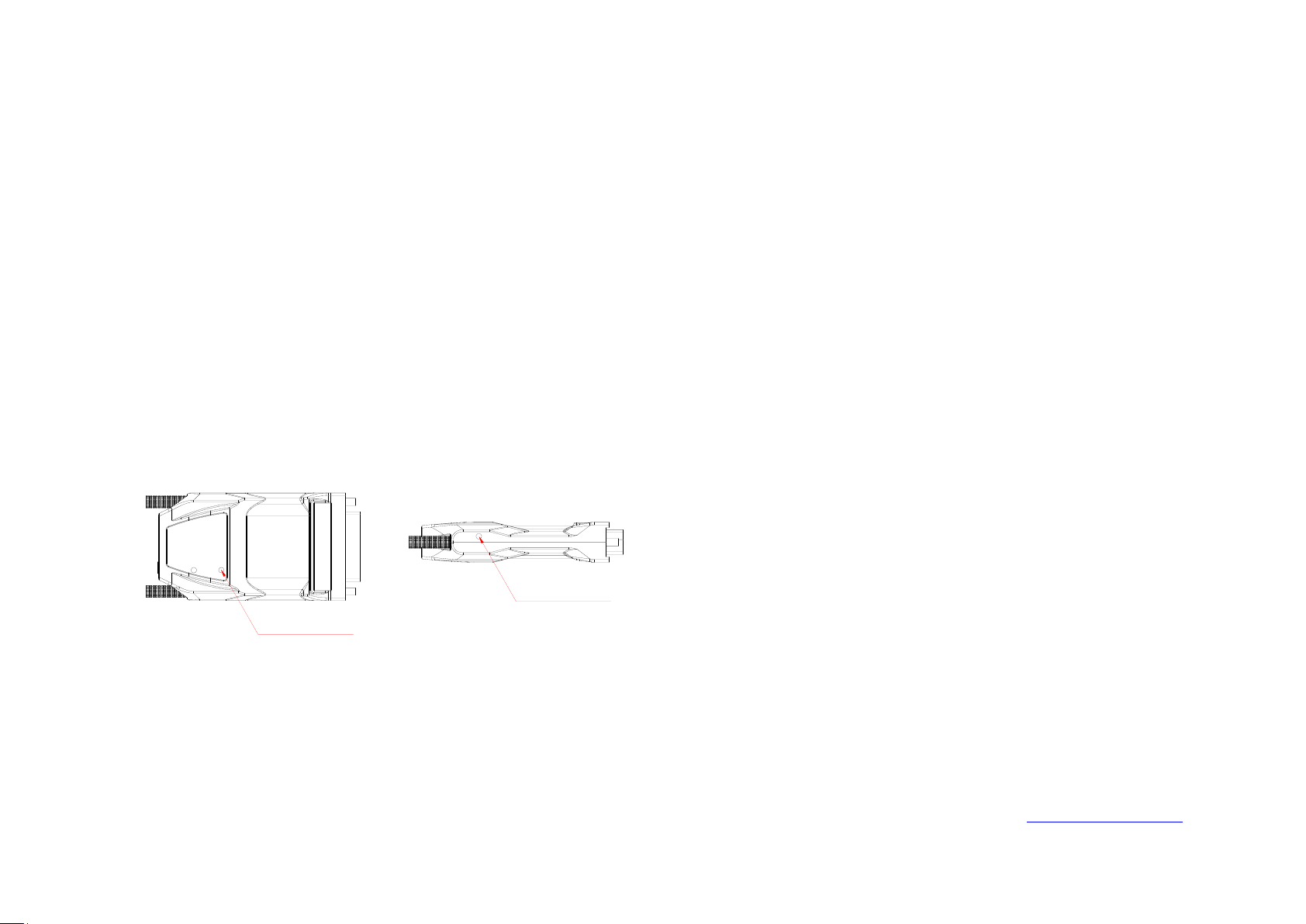
Push the EDID PRGM. button of the transmitter with a narrow pin. Then, status LED
will be turned off.
Figure 6 – Position of EDID-PRGM. button and Status LED
Step 4
Connect the transmitter to the display not to the PC. Then the status LED will
begin to blink rapidly. It indicates reading the EDID from the display and storing it in
the EEPROM. After 7~8 sec, the status LED blink slowly and it indicates completion
of all procedure.
Step 5
Disconnect the transmitter from the display.
1-5 Self-EDID Programming Procedure
EDID-PRG. Button
Status LED
Page 5
Product Specifications
DVFX-110-TR Optical DVI Extension Modules
Compliance with DVI standard: Supports DVI1.0, fully
implemented by fiber-optic communication and DDC2B by virtual
DDC.
Extension limit: 1km (3,280feet) for WUXGA (1920x1200) at 60Hz
refresh rate.
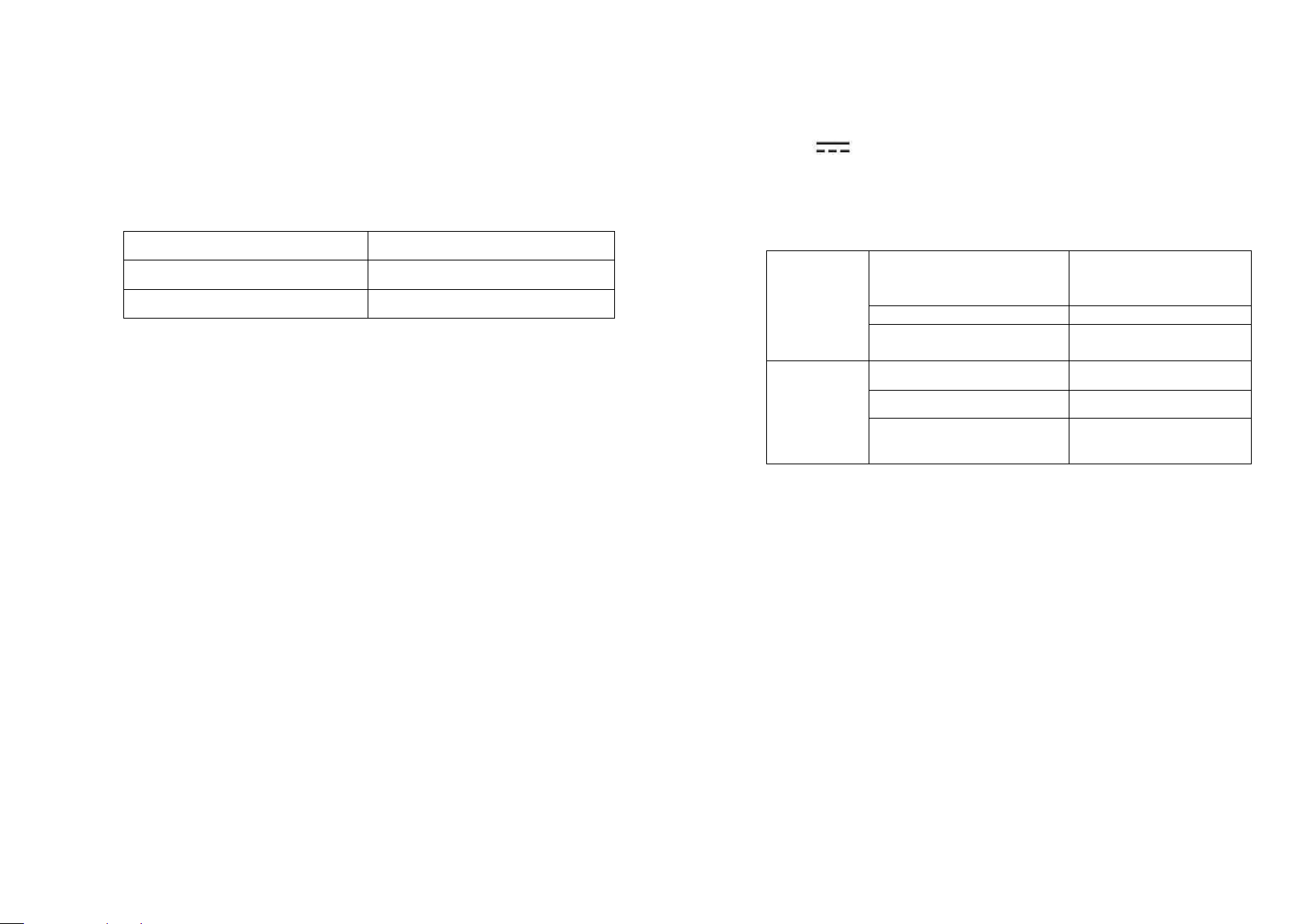
Fiber Type
Extension Length at WUXGA
Multi-mode Fiber
500meters (1,640ft)
Single-mode Fiber
1km (3,280ft)
Graphic transmission bandwidth: Supports up to WUXGA, 60Hz,
or 1.65Gbps bandwidth per graphic channel.
An error can be occurred when using certain pattern with XGA
(1024x768) at 70 or 72Hz, 1080i at 59.94 or 60Hz.
Fiber-optic connection: The transmitter and receiver modules of
DVFX-110 have one (1) SC receptacles so as to be connected with
one (1) SC simplex single or multi-mode fibers, having 9(8)/125m
or 62.5(50)/125m core.
DDC connection: Virtual DDC by Self-EDID programming.
Mechanical specifications of transmitter and receiver modules
Dimensions (WDH): 39 x 68 x 14.6mm
Environmental Specifications
Operating temperature: 0 to 40°C (Medical), 0 to 50°C (General)
Storage temperature: - 30°C to 70°C
Operating humidity: 10% to 85%
AC/DC Power Adapter (General, Medical)
Power Input: AC 100-240V, 50/60Hz
Power Output: +5 V, 2A SMPS DC-power Adapter
Cord DC Jack: Core is 5 V and outer is GND.
Model name: BPM010S05FXX (Medical adapter only)
Manufacturer: BridgePower Corp. (Medical adapter only)
1-7 Product Specifications
Product Specifications
Label Specification
+5V 2.0A: Direct Current
Operation Condition
Operating
condition
Temperature (C)
0 to 40 (Medical)
0 to 50 (General)
Relative humidity (%)
10-85
Atmospheric Pressure
(hPa)
700 – 1060
Transport
and storage
condition
Temperature (C)
-30-70
Relative humidity (%)
10-95
Atmospheric Pressure
(hPa)
500 - 1060
1-8 Product Specifications (Continued)
Page 6
Warranty Information
1 (One) Year Warranty
Opticis warrants this optical DVI extension module to be free from defects in
workmanship and materials, under normal use and service, for a period of
one (1) year from the date of purchase from Opticis or its authorized resellers.
If a product does not work as warranted during the applicable warranty period,
Opticis shall, at its option and expense, repair the defective product or part,
deliver to customer an equivalent product or part to replace the defective item,
or refund to customer the purchase price paid for the defective product.
All products that are replaced will become the property of Opticis.
Replacement products may be new or reconditioned.
Any replaced or repaired product or part has a ninety (90) day warranty or the
reminder of the initial warranty period, whichever is longer.
Opticis shall not be responsible for any software, firmware, information, or me
mory data of customer contained in, stored on, or integrated with any product
s returned to Opticis for repair under warranty or not.
Warranty Limitation and Exclusion
Opticis shall have no further obligation under the foregoing limited warranty if
the product has been damaged due to abuse, misuse, neglect, accident,
unusual physical or electrical stress, unauthorized modifications, tampering,
alterations, or service other than by Opticis or its authorized agents, causes
other than from ordinary use or failure to properly use the product in the
application for which said product is intended.
Dispose of Old Electrical & Electronic Equipment
(Applicable in the European Union and other European countries with separate systems)
This symbol on the product or on its packaging indicates that this
product shall not be treated as household waste. Instead it shall be
handed over to the applicable collection point for the recycling of
electrical and electronic equipment. By ensuring this product is
disposed of correctly, you will help prevent potential negative
consequences for the environment and human health, which could
otherwise be caused by inappropriate waste handling of this product.
The recycling of materials will help to conserve natural resources. For more detailed
information about recycling of this product, please contact your local city office, your
household waste disposal service or the shop where you purchased the product.
1-9 Warranty Information
WARNING: Do not touch signal input, signal output of other connectors, and
the patient simultaneously.
WARNING: Do not connect any accessory except provided by Opticis. Any
damage caused other power adapters or accessories will not be taken any
responsibility by Opticis.
Warning for Medical Usage
WARNING: External equipment intended for connection to signal input, signal
output or other connectors, shall comply with relevant IEC Standard(e.g.,
IEC60950 for IT equipment and IEC60601-1 series for medical electrical
equipment). In addition, all such combination-system-shall comply with the
standard IEC60601-1 and/or IEC60601-1-1 harmonized national standard or
the combination. If, in doubt, contact a qualified technician or your local
representative.
WARNING: (Detachable) Listed, Type SJT, min. No. 18 AWG, 3-conductor
terminating in molded-on Listed "Hospital Grade", parallel blade, grounding type
attachment plug rated minimum 15 A, 125 V.
Maximum 4.0 m long. Making tag provided indicating "Grounding reliability can
only be achieved when the equipment is connected to an equivalent receptacle
marked "Hospital Only" or "Hospital Grade"
1-10 Warning
Page 7
UL/EN Statement
This equipment has been tested and found to comply with the limits for
medical devices in UL/EN 60601-1, 60601-1-2 and FCC/CE. These limits
are designed to provide reasonable protection against harmful interference in
a typical medical installation.
This equipment generates uses and can radiate radio frequency energy and,
if not installed and used in accordance with the instructions, may cause
harmful interference to other devices in the vicinity. However, there is no
guarantee that interference will not occur in a particular installation. If this
equipment does cause harmful interference to other devices, which can be
determined by turning the equipment off and on, the user is encouraged to try
to correct the interference by one or more of the following measures:
Reorient or relocate the receiving device.
Increase the separation between the equipment.
Connect the equipment into an outlet on a circuit different from that
to which the other device(s) are connected.
Consult the manufacturer or field service technician for help.
Type of protection against electric shock: Class I equipment
Degree of protection against electric shock: Not classified - no applied
parts
Classification according to the degree of protection against ingress of
water as detailed in the current edition of IEC 529: IPX0, ordinary
equipment
This equipment is not suitable for use in the presence of flammable
anesthetics or oxygen
Mode of operation: continuous operation
Certification of Eye Safety
This laser product is inside implemented by using 1310/1550nm optical
module, manufactured by Opticis Co., Ltd., which are all certified by UL/EN
60601-1, 60601-1-2 referred in Accession Number 07-1334-0217 as classified
in Class1 LASER eye safety.
1-11 Regulatory Statements
Guidance and Manufacturer’s Declaration
Guidance and Manufacturer’s Declaration – Electromagnetic Emissions
This Device is intended for use in the electromagnetic environment specified below. The user of the Device
should assure that it is used in such an environment.
Emissions Test
Compliance
Electromagnetic Environment - Guidance
RF Radiated
Emissions
CISPR 11
Group 1
This Device uses RF energy only for its internal function.
Therefore, its RF radiated emissions are very low and are not
likely to cause any interference in nearby electronic equipment.
RF Conducted
Emissions
CISPR 11
Class A
This Device is suitable for use in all establishments other than
domestic and those directly connected to a low-voltage power
supply network which supplies buildings used for domestic
purposes.
Harmonic Emissions
IEC 61000-3-2
Class A
Voltage
Fluctuations/Flicker
Emissions
IEC 61000-3-3
Complies
Guidance and Manufacturer’s Declaration – Electromagnetic Immunity
This Device is intended for use in the electromagnetic environment specified below. The user of the Device
should assure that it is used in such an environment.
Immunity Test
IEC 60601 Test Level
Compliance Level
Electromagnetic Environment Guidance
Electrostatic
Discharge (ESD)
IEC 61000-4-2
±6 kV Contact
±8 kV Air
±6 kV Contact
±8 kV Air
Floors should be wood, concrete
or ceramic tile. If floors are
covered with synthetic material,
the relative humidity should be at
least 30%.
Electrical Fast
Transient/Burst
IEC 61000-4-4
±2 kV for power supply
lines
±1 kV for input/output
lines
±2 kV for power
supply lines
±1 kV for input/output
lines
Mains power quality should be
that of a typical commercial or
hospital environment.
Surge
IEC 61000-4-5
±1 kV differential mode
±2 kV common mode
±1 kV differential
mode
±2 kV common mode
Mains power quality should be
that of a typical commercial or
hospital environment.
Voltage Dips, Short
Interruptions and
Voltage Variations
on Power Supply
Input Lines
IEC 61000-4-11
<5 % UT
(>95 % dip in UT)
for 0.5 cycle
40 % UT
(60 % dip in UT)
for 5 cycles
70 % UT
(30 % dip in UT)
for 25 cycles
<5 % UT
(>95 % dip in UT
for 5 sec
<5 % UT
(>95 % dip in UT)
for 0.5 cycle
40 % UT
(60 % dip in UT)
for 5 cycles
70 % UT
(30 % dip in UT)
for 25 cycles
<5 % UT
(>95 % dip in UT
for 5 sec
Mains power quality should be
that of a typical commercial or
hospital environment.
If the user of the device requires
continued operation during power
mains interruptions, it is
recommended that the device be
powered from an uninterruptible
power source.
Power Frequency
(50/60 Hz)
Magnetic Field
IEC 61000-4-8
3 A/m
3 A/m
Power frequency magnetic fields
should be at levels characteristic
of a typical location in a typical
home or hospital environment.
1-12 Regulatory Statements
Page 8
Guidance and Manufacturer’s Declaration
Guidance and Manufacturer’s Declaration – Electromagnetic Immunity
This Device is intended for use in the electromagnetic environment specified below. The user of the
Device should assure that it is used in such an environment.
Immunity Test
IEC 60601 Test Level
Compliance Level
Electromagnetic Environment
- Guidance
Conducted RF
IEC 61000-4- 6
Radiated RF
IEC 61000-4-3
3 Vrms
150 kHz to 80 MHz
3 V/m
80 MHz to 2.5 GHz
3 V
3 V/m
Portable and mobile RF commu
nications equipment should be
used no closer to any part of th
e Device, including cables, than
the recommended separation di
stance calculated from the equa
tion applicable to the frequency
of the transmitter.
Recommended Separation
Distance
d = 1.2√P
d = 1.2√P (80 MHz to 800 MHz)
d = 2.3√P (800 MHz to 2.5
GHz)
Where P is the maximum output
power rating of the transmitter i
n watts (W) according to the tra
nsmitter manufacturer and d is t
he recommended separation di
stance in meters (m).
Field strengths from fixed RF tr
ansmitters, as determined by an
electromagnetic site survey, sh
ould be less than the complianc
e level in each frequency range.
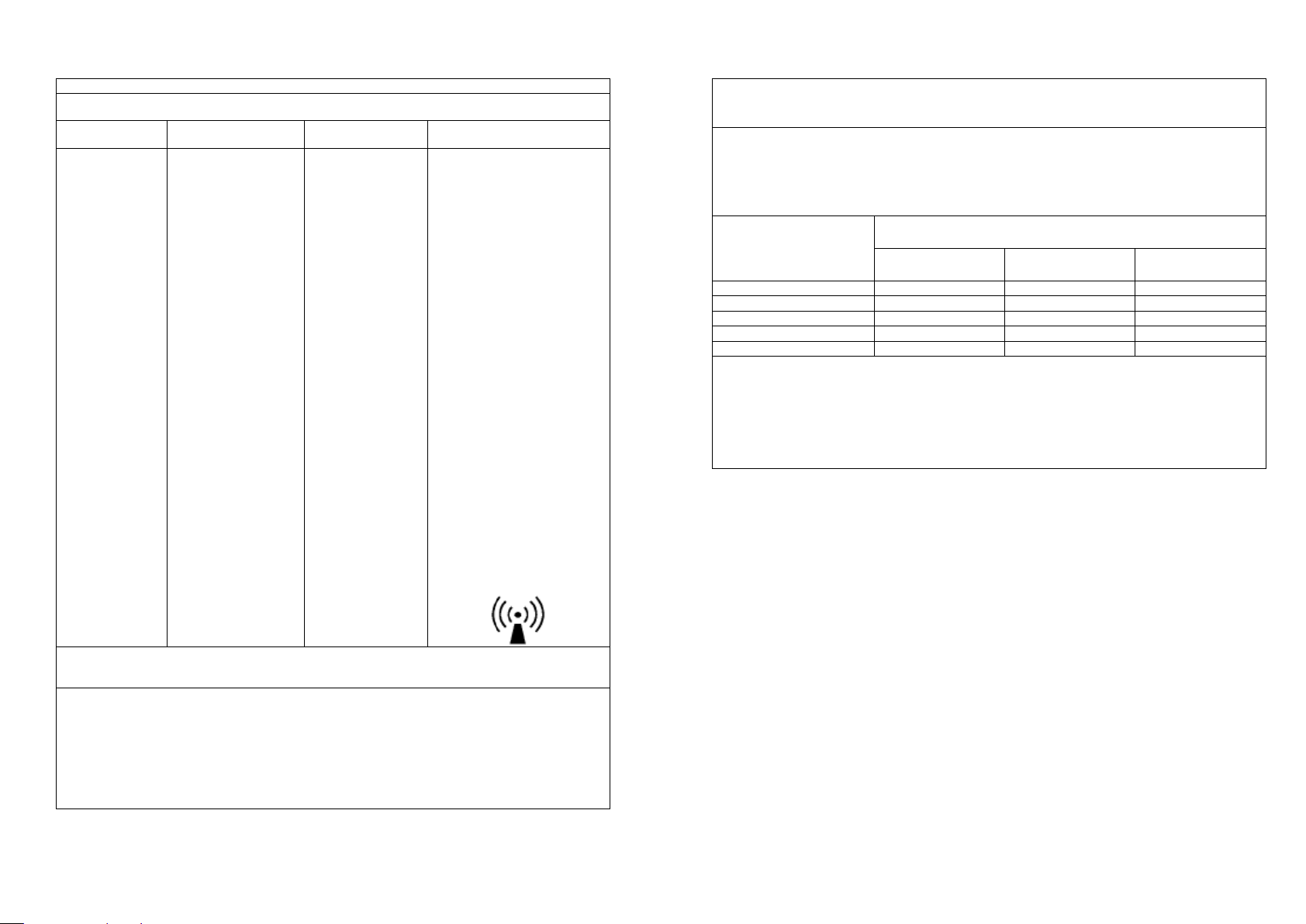
Interference may occur in the vi
cinity of equipment marked with
the following symbol:
Note 1: At 80 MHz and 800 MHz, the higher frequency range applies.
Note 2: These guidelines may not apply in all situations. Electromagnetic propagation is affected by
absorption and reflection from structures, objects and people.
a Field strength from fixed transmitters such as base stations for radio (cellular/cordless)
telephones and land mobile radios, amateur radio, AM and FM radio broadcast and TV
broadcast cannot be predicted theoretically with accuracy. To assess the electromagnetic
environment due to fixed RF transmitters, an electromagnetic site survey should be considered.
If the measured field strength in the location in which the Device is used exceeds the applicable
RF compliance level above, the Device should be observed to verify normal operation. If
abnormal performance is observed, additional measures may be necessary, such as reorienting or relocating the Device.
b Over the frequency range 150 kHz to 80 MHz, field strengths should be less than 3 V/m.
1-13 Regulatory Statements
Guidance and Manufacturer’s Declaration
Recommended Separation Distance Between Portable and Mobile RF Communication
Equipment and the Device.
The Device is intended for use in the electromagnetic environment in which radiated RF
disturbances are controlled. The user of the Device can help prevent electromagnetic interference
by maintaining a minimum distance between portable and mobile RF communication equipment
(transmitters) and the Device as recommended below, according to the maximum output power of
the communications equipment.
Rated Maximum Output
Power of Transmitter
(Watts)
Separation Distance According to Frequency of Transmitter (meters)
150 kHz to 80 MHz
d = 1.2√P
80 MHz to 800 MHz
d = 1.2√P
800 MHz to 2.5 GHz
d = 2.3√P
0.01
0.12
0.12
0.23
0.1
0.38
0.38
0.73 1 1.2
1.2
2.3
10
3.8
3.8
7.3
100
12
12
23
For transmitters rated at a maximum output power not listed above, the recommended separation
distance d in meters (m) can be estimated using the equation applicable to the frequency of the
transmitter, where P is the maximum output power of the transmitter manufacturer.
Note 1: At 80 MHz and 800 MHz, the higher frequency range applies.
Note 2: These guidelines may not apply in all situations. Electromagnetic propagation is affected
by absorption and reflection from structures, objects and people.
1-14 Regulatory Statements (Continued)
Page 9

© 2015 Opticis Co., Ltd. All Rights Reserved
Revision 1.6. 2, Jan, 2015
Opticis Locations
Headquarters
Opticis Co., Ltd.
# 16Fl, Kins Tower
8 Sungnam-daero, 331 beon-gil,
Bundang-gu,
Seongnam-si, Gyunggi-do, 463-844
South Korea
Te l: +82 (31) 719-8033
Fax: +82 (31) 719-8032
www.opticis.com
For order support, please contact your Distributor or Reseller.
For technical support, check with the Opticis web site www.opticis.com or
contact [email protected]
 Loading...