

Page 1

Quick Start Guide
OSD2888
MANAGED 12 x 10/100/1000BASE-T
& 4 x 10G SFP ETHERNET SWITCH
Page 2

Page 3

OPTICAL SYSTEMS DESIGN
INDEX 1
1
INTRODUCTION ...................................................................................................................... 4
2
TECHNICAL SUMMARY ........................................................................................................ 4
2.1
B
RIEF DESCRIPTION
2.2
A
PPLICATIO
2.3
FEATURES AND BENEFITS ................................................................................................. 4
2.4
TECHNICAL SPECIFICATIONS ........................................................................................... 5
3
INSTALLATION........................................................................................................................ 6
4
OSD2888 FRONT AND REAR PANELS................................................................................. 7
4.1
FRONT PANEL ....................................................................................................................... 7
4.2
REAR P
5
POWER SUPPLY CONNECTIONS ........................................................................................ 7
6
LED INDICATORS ................................................................................................................... 8
7
FITTING SFP CONNECTORS ................................................................................................ 9
8
CLI OVERVIEW ..................................................................................................................... 10
8.1
C
ONNECT TO
8.2
CLI
COMMAND FOR IP CONFIGURATION
GUI OVERVIEW ................................................................................................................................. 13
8.3
D
EFAULT SETTING
8.4
L
OG INTO THE SWITCH
8.5
GUI O
8.6
IP C
ONFIGURATION
8.7
U
SERS AUTHENTICATION
8.8
S
AVE CONFIGURATION TO START-UP
8.9
P
ORT SPEED SETTING
9
WARRANTY ............................................................................................................................ 17
9.1
WARRANTY PERIOD .......................................................................................................... 17
9.2
REPAIRS ................................................................................................................................ 17
9.2.1 WARRANTY REPAIRS .................................................................................................... 17
9.2.2 OUT-OF-WARRANTY REPAIRS .................................................................................... 17
9.2.3 SITE REPAIRS .................................................................................................................. 17
9.2.4 EXCLUSIONS ................................................................................................................... 17
NS .......................................................................................................................... 4
ANEL
VERVIEW
FIGURE 1: FRONT PANEL .................................................................................................................... 7
FIGURE 2: REAR PANEL ...................................................................................................................... 7
FIGURE 3: POWER CONNECTION ...................................................................................................... 7
FIGURE 4: FITTING/REMOVING SFP CONNECTORS ..................................................................... 9
TABLE 1: TECHNICAL SPECIFICATIONS ......................................................................................... 5
TABLE 2: LED FUNCTION ................................................................................................................... 8
.................................................................................................................. 4
............................................................................................................................ 7
CLI .................................................................................................................... 10
................................................................................. 11
................................................................................................................... 13
............................................................................................................ 13
....................................................................................................................... 13
................................................................................................................. 14
........................................................................................................ 15
...................................................................................... 16
.............................................................................................................. 16
PAGE 3
OSD2888 QUICK START GUIDE
DOC ID: 10118501
Page 4

OPTICAL SYSTEMS DESIGN
1 INTRODUCTION
Thank you for choosing the OSD2888 16-Port (12x1G + 4x10G) Managed Ethernet Switch. This Quick Start
Guide is designed to guide you through the installation and basic software functions.
2 TECHNICAL SUMMARY
2.1 BRIEF DESCRIPTION
The OSD2888 is a managed 12 port 10/100/1000BASE-T and 4 port 10G SFP Ethernet Switch. Please see
OSD2888 datasheets for options available.
2.2 APPLICATIONS
▲
Managed L3 switch for small to mediumsized Enterprise networks requiring high
throughput
▲
Redundant and self-healing network
2.3 FEATURES AND BENEFITS
General
• L2 managed Ethernet switch
• ITU-TG.8032 Ethernet Ring Protection Switching
• CPU Memory 128MB
• User-friendly web browser based GUI
• CLI and SNMP management
Port Control
• Port speed, duplex mode, and flow control
• Port status -- link monitoring
• Port statistics -- MIB counters
• Port cable diagnostics
QoS
• Traffic classes (1, 2, or 4, 8 active priorities)
• Port default priority and user assigned priority
• Scheduler priority
• QoS control
• Storm control
L2 Switching
•
IEEE 802.1D Bridge with auto MAC
learning/aging
• IEEE 802.1Q static VLAN
• Private VLAN (static)
• 25Gbps switching backplane
• IEEE 802.1Q-2005–Rapid spanning tree (RSTP)
Security
• Port-based 802.1X
• Web and CLI authentication and authorization
OAM
• IEEE 802.3ad Link aggregation, static and LACP
• DHCP client
▲
Industrial IP communications for rugged
environments
▲
Available with either DC or AC powering.
The DC version has dual redundant inputs
as standard whereas redundant AC powering
is optional for the AC version
• IEEE 802.1ag Service OAM
• IEEE 802.3ah Link OAM
Multicasting
•
IGMP Snooping (IGMPv2, IGMPv3)
• Multicast Listener Discovery (MLD) v1 and v2
Power Saving
•
Ethernet energy efficient
– Link down power savings
– Scales power based on cable length
• Thermal protection
Management
• HTTP server
• Web management
• CLI console port
• Management access filtering
• System Log
• Software download through web
• SNMPv1/v2c/v3 Agent
• IEEE 802.1AB-2005 Link Layer Discovery, LLDP
• Configuration download or upload
• RFC 1213MIB II
• RFC 3621 LLDP-MED power
• RFC 3635 Ethernet-like MIB
• RFC 4188 Bridge MIB
• Private MIB framework
• IEEE 802.1 MSTP MIB
• IEEE 802.1AB LLDP MIB
PAGE 4
OSD2888 QUICK START GUIDE
DOC ID: 10118501
Page 5

OPTICAL SYSTEMS DESIGN
2.4 TECHNICAL SPECIFICATIONS
SPECIFICATION PERFORMANCE
TABLE 1: TECHNICAL SPECIFICATIONS
Electrical Data Interface
Optical Data Interface IEEE802.3z 1000Base-Lx/Sx
Copper Port Connector RJ45 x 12
Optical Port Connector SFP (LC or SC)
Console Connector Mini-USB
Operating Mode
Optical Port Connectors
SFP Options
Indicators
Operating Temperature
Relative Humidity
IEEE802.3i/802.3u/802.3ab, 10/100/1000Base-T Ethernet
Half or full duplex for 10/100/1000
Full duplex for 1G
Store-and-Forward
Half-duplex back-pressure and IEEE802.3x full-duplex flow control
SFP x 4 for uplink/trunk ports
Short haul, long haul, single fiber operation, etc.
Please consult OSD Datasheets #102100XX and #10210G0XX for 1G
and 10G or contact OSD
12 x 10/100/1000Base-T, 1000Base-X: Link/Activity/Speed
4 x 10G Link/Avctivity/Speed
1 x Power
-20°C to +75°C
5 to 95% non-condensing
Power Requirements
Power Connector
Dimensions of Enclosure (mm) 443W x 300D x 44H
Weight (kg)
+10 to +36VDC @ 30VA Max
90 to 264VAC @ 40VA Max
4 way Terminal Block for DC powered version
One IEC power inlet module for the standard AC powered version
Two IEC power inlet modules for the optional redundant AC powered version
5.1
PAGE 5
OSD2888 QUICK START GUIDE
102288802
DOC ID: 10118501
Page 6
OPTICAL SYSTEMS DESIGN
3 INSTALLATION
ELECTROMAGNETIC COMPATIBILITY
WARNING: This is a Class A product. In a domestic environment this product may cause radio
interference in which case the user may be required to take adequate measures.
OPTICAL OUTPUT OPERATION
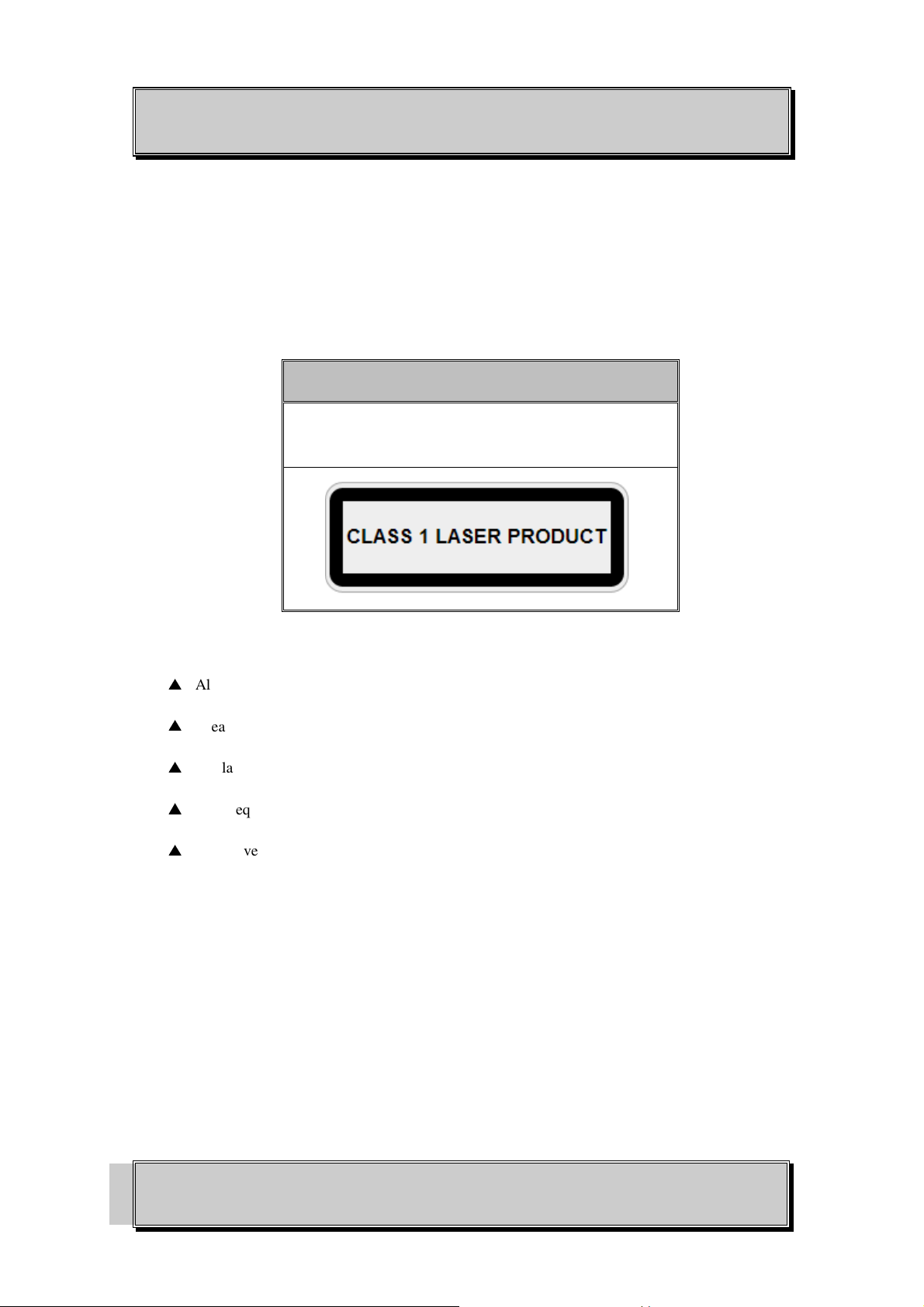
WARNING: Laser Safety: Class 1 Laser Product (SFP) per IEC 60825-1:2014 standard.
Class 1
The OSD2888 is a Class 1 laser product when SFP are
fitted
PRECAUTIONS
▲
All service personnel should be provided training as to the hazards of direct viewing of laser
radiation and of the precautionary measures during servicing of equipment
▲
Areas where laser products are installed should be restricted in access to trained service
personnel only and appropriate warning signs posted in the work area.
▲
All laser apertures should be covered by protective covers when not connected to optical
fibers. Never leave outputs uncovered.
▲
Laser equipment should be positioned above or below eye level where possible. Apertures
should be positioned away from personnel.
▲
Protective eyewear should be worn in the vicinity of laser equipment.
PAGE 6
OSD2888 QUICK START GUIDE
DOC ID: 10118501
Page 7
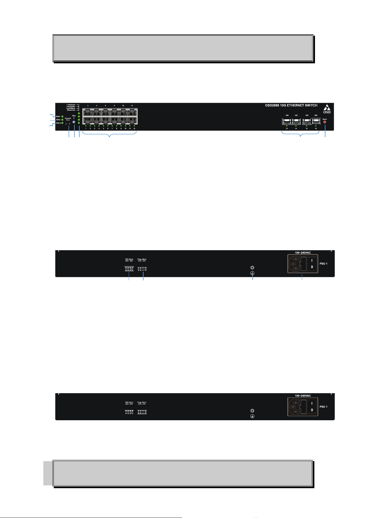
4 5 6
7
8
9
OPTICAL SYSTEMS DESIGN
4 OSD2888 FRONT AND REAR PANELS
4.1 FRONT PANEL
1
2
3
FIGURE 1: FRONT PANEL
1. PSU1 Status LED
2. PSU2 Status LED
3. Status LED
4. USB Console Port
5. View LED Mode button
6. View mode LEDs indicators
7. 12 x 10/100/1000M COPPER ports with Link/Speed/Status LED
8. 4 x 10G Trunk/Uplink SFP ports with Link/Speed/Status LED
9. Reset Button
4.2 REAR PANEL
10 11 12 13
FIGURE 2: REAR PANEL
10. PSU Alarm Output connector
11. Programmable Alarm Output Connector
12. Earth/Ground screw
13. PSU 1 Power Supply Input/Fuse/Switch
5 Power Supply Connections
Connect the IEC Power connectors to PSU 1 located on the rear of the unit.
The OSD2888 requires external 90 to 264VAC @ 40VA Max power.
FIGURE 3: POWER CONNECTION
PAGE 7
OSD2888 QUICK START GUIDE
DOC ID: 10118501
Page 8
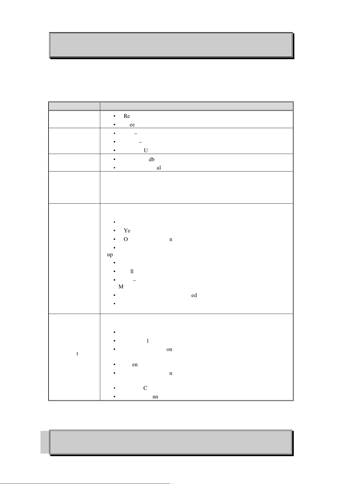
LED Function
•
•
•
•
6 LED Indicators
PSU 1
PSU 2
Status
View Mode LED
Indicators
•
•
•
•
Controlled by View LED Mode Button. Pressing the Mode button cycles the
Copper Port Status LED indication.
Speed Mode Duplex Mode Status Mode Reserved
OPTICAL SYSTEMS DESIGN
TABLE 2: LED FUNCTION
Red – PSU 1 Not connected or faulty
Green – PSU 1 On
Red – PSU 2 Not connected or faulty
Green – PSU 2 On
Off – PSU 2 not available/fitted
Red – Standby/Initialization Mode
Green – Normal status
Copper Port Status
LED
Fiber Port Status
LED
The Copper Port Status LED will indicate different information.
Speed Mode:
•
Green – 1Gbps
•
Yellow – 100MBps
•
Off – No Connection
•
Blinking – Traffic
Duplex Mode:
•
Green – Full Duplex
•
Yellow – Half Duplex
•
Off – No Connection
Status Mode:
•
Green – Connection established
•
Off – No Connection
The Fiber Port Status LED will indicate different information.
Speed Mode:
•
Green – 1Gbps or 10Gbps
•
Yellow – 100MBps
•
Off – No Connection
Duplex Mode:
•
Green – Full Duplex
•
Off – No Connection
Status Mode:
•
Green – Connection established
Off – No Connection
PAGE 8
OSD2888 QUICK START GUIDE
DOC ID: 10118501
Page 9
OPTICAL SYSTEMS DESIGN
7 Fitting SFP Connectors
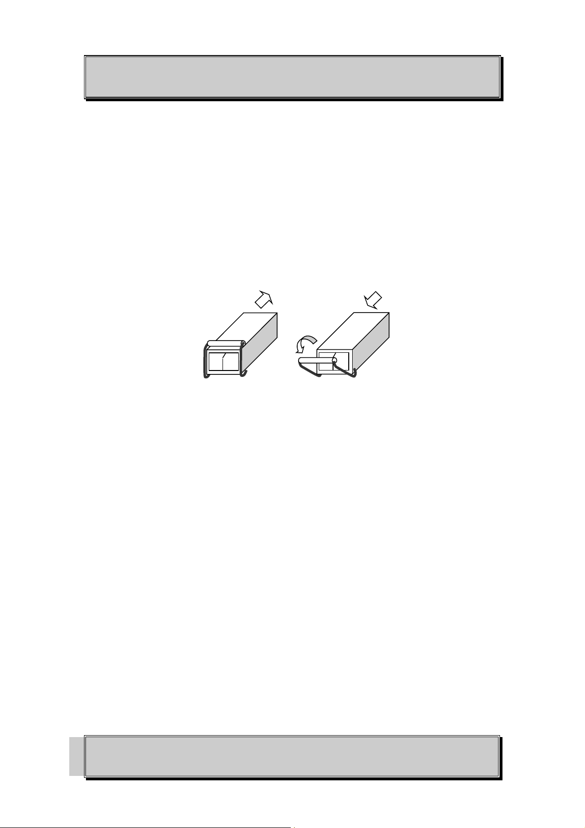
Care should be taken when inserting/removing the SFP connectors from the SFP port as SFP modules
are Electrostatic (ES) sensitive and Electrostatic Discharge (ESD) precautions should be taken when
installing. Ensure that the SFP is fully engaged and latched into position.
Inserting SFP – Ensure that the SFP lever is in the locked position and insert into appropriate SFP
port. Gently push the SFP until it locks into place. Remove plastic/rubber dust cap and fit appropriate
fiber cable.
Removing SFP – Remove fiber connector. Pull the SFP lever down to unlock SFP from housing.
Using the lever, gently pull the SFP out.
Fiber SFP
1
Inserting
SFP
FIGURE 4: FITTING/REMOVING SFP CONNECTORS
Removing
SFP
2
PAGE 9
OSD2888 QUICK START GUIDE
DOC ID: 10118501
Page 10
OPTICAL SYSTEMS DESIGN
8 CLI OVERVIEW
8.1 CONNECT TO CLI
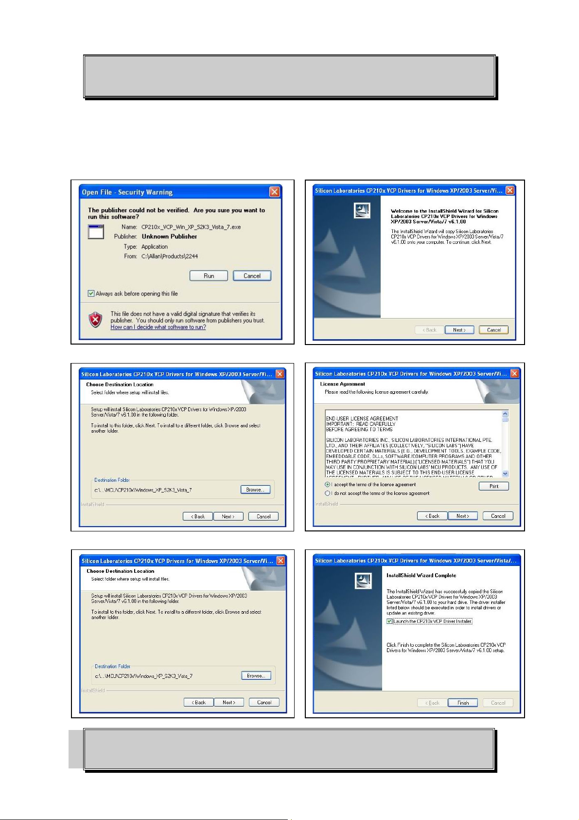
The Silicon Laboratories CP210x VCP Drivers is required to be installed on the PC before connecting
the switch.
PAGE 10
OSD2888 QUICK START GUIDE
DOC ID: 10118501
Page 11
OPTICAL SYSTEMS DESIGN
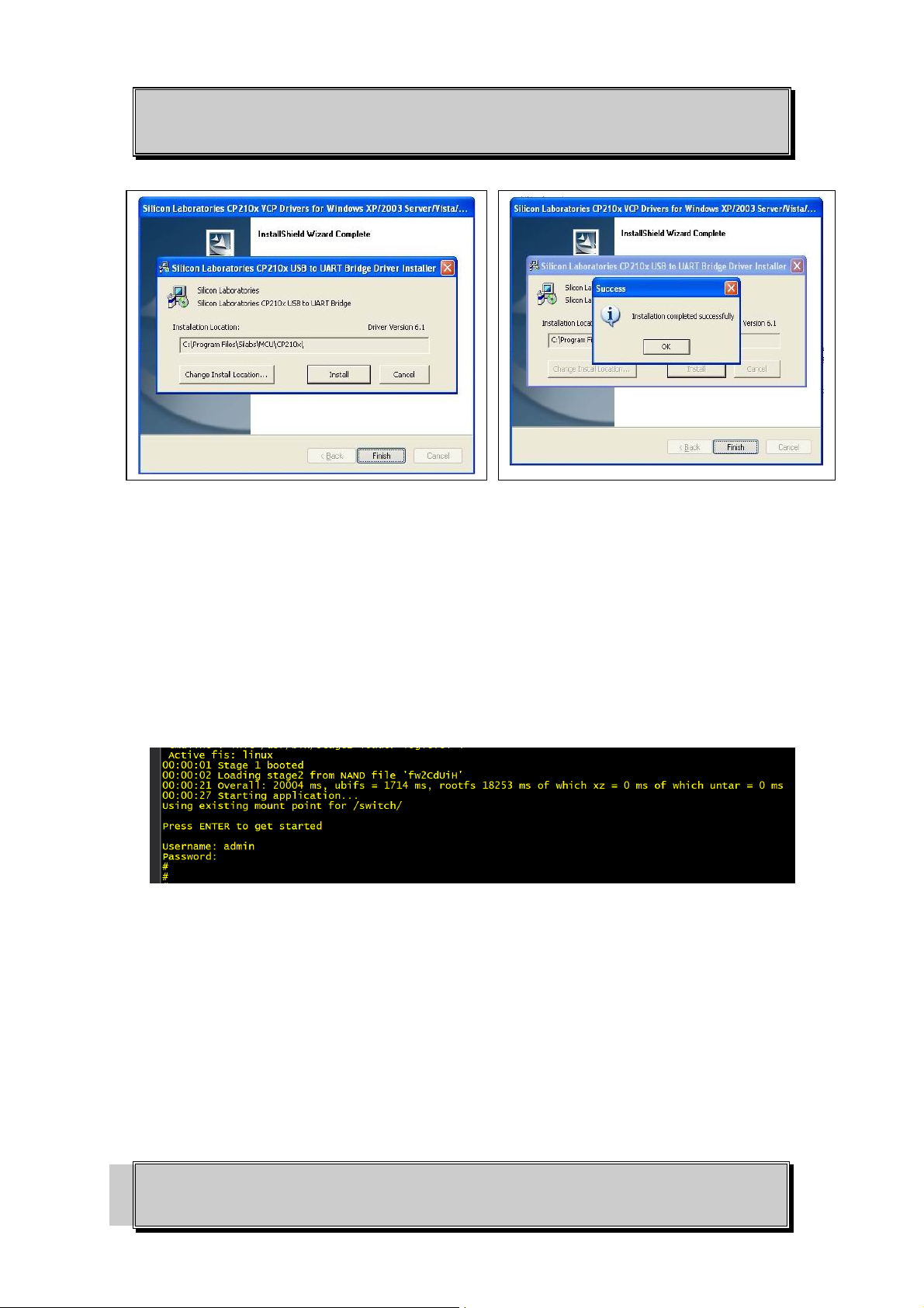
1. Connect the Console Port on OSD2888 (Mini USB) to PC with USB cable.
2. Using HyperTerminal or similar, set up the following parameters.
• Baud Rate: 115200
• Data Bits: 8
• Parity: None
• Stop Bits: 1
• Flow Control: None
3. Check the link by pressing <ENTER>. The line should jump to the next line.
4. Using the Username and password to login the switch
• Default Username: admin
• Default Password: (None)
8.2 CLI COMMAND FOR IP CONFIGURATION
The Command Line Interface (CLI) is a useful tool for checking link status and debugging link
connections. To enable the use of CLI the OSD2888 must be connected to a PC with a USB port using
a Mini-USB cable. Using a terminal emulation program such as Hyperterminal, a number of command
lines specific to the OSD2888 can be implemented
PAGE 11
OSD2888 QUICK START GUIDE
DOC ID: 10118501
Page 12
OPTICAL SYSTEMS DESIGN
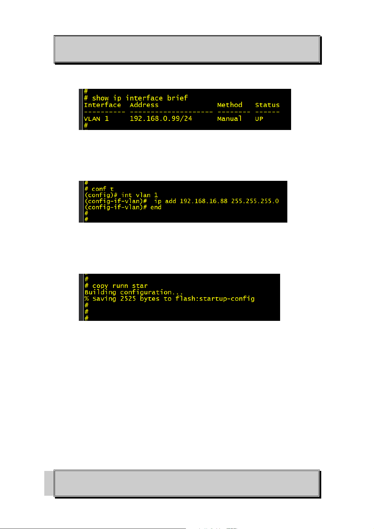
• show ip interface brief: Displays the current IP address and subnet mask.
• configure terminal -> interface vlan 1 -> ip address <IP address> <subnet mask>: Setup the
switch IP address. The following picture is an example of how to configure the device IP into
192.168.16.88
• copy running-config startup- config: Save the current configuration to start-up configuration.
The configuration will be saved into Flash so that the desired configuration setup will be in
effect at the next startup.
PS: All configuration changes must be saved otherwise all the changes will be lost after
rebooting!
PAGE 12
OSD2888 QUICK START GUIDE
DOC ID: 10118501
Page 13
OPTICAL SYSTEMS DESIGN
GUI Overview
8.3 DEFAULT SETTING
•
IP Address: 192.168.0.99
•
Subnet Mask: 255.255.255.0
•
Gateway: 192.168.0.1
•
User Name: admin
•
Password: (None)
8.4 LOG INTO THE SWITCH
•
Connect an Ethernet cable to any switch port from a PC. It may be necessary to change the
PC’s network IP address to connect to the switch. (i.e.: 192.168.0.2). Make sure the IP
address of the PC and the switch in the same subnet.
•
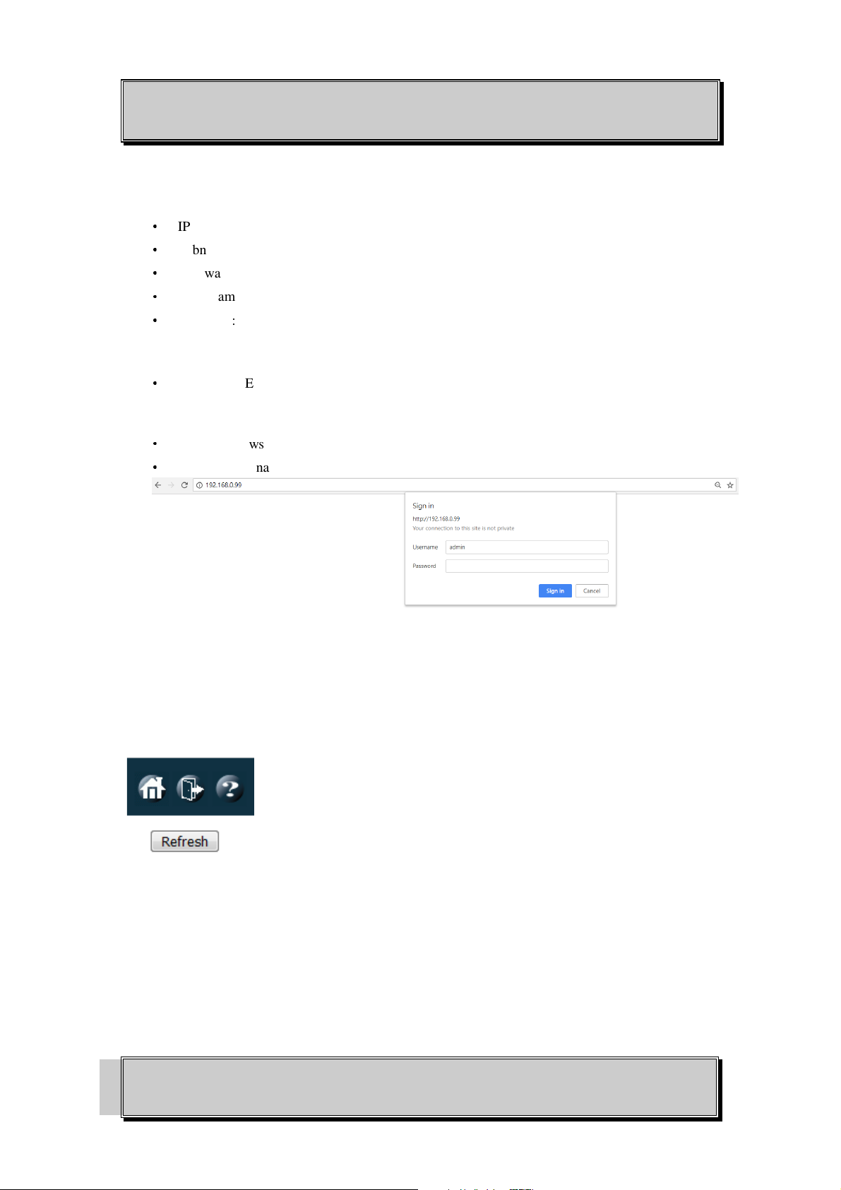
In a web browser, enter the URL 192.168.0.99.
•
Enter the username (admin) and password (none/blank) and click “Sign In”.
8.5 GUI OVERVIEW
This Quick Start Guide will only show a few main or important features to get the user running the
OSD2888 successfully. On the top right hand of the GUI screen there are a few icons available to
quickly navigate or obtain help for each GUI menu items.
Home Logout Help
H
OME:
Clicking the Home button will exit any GUI current screen and display the panel status.
L
OGOUT:
H
ELP:
display all functions and input arguments for that page.
Clicking the Logout button will logout the current user and close the windows session
Clicking the Help button will open a help window for the current open menu window and
PAGE 13
OSD2888 QUICK START GUIDE
DOC ID: 10118501
Page 14
OPTICAL SYSTEMS DESIGN
8.6 IP CONFIGURATION
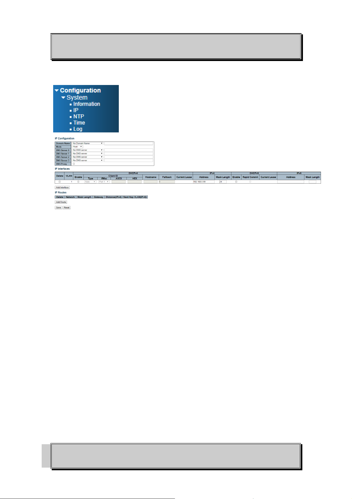
In the treemap on the left of the GUI, expand the Configuration System IP.
Enter the IPv4 address and Mask Length in the table.
Choose the management VLAN ID to access that IP in VLAN table if VLAN function is required.
If multiple IP addresses are required, click Add Interface to add more IP interfaces.
Click Save to save the configuration.
Use new IP address to access the switch.
PS: All configuration changes must be saved otherwise all the changes will be lost after
rebooting!
PAGE 14
OSD2888 QUICK START GUIDE
DOC ID: 10118501
Page 15
OPTICAL SYSTEMS DESIGN
8.7 USERS AUTHENTICATION
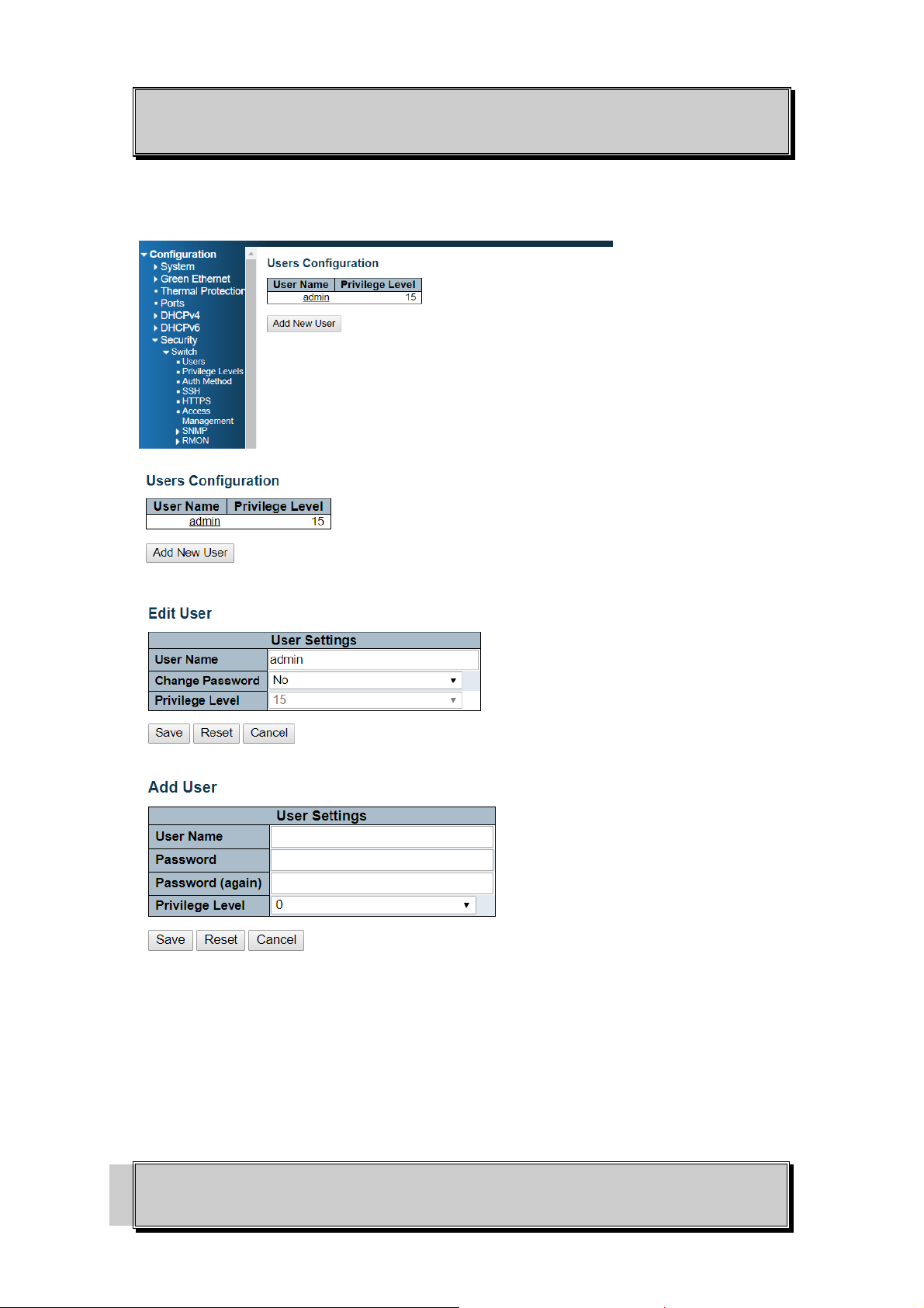
In the tree map on the left, expand the Configuration Security Switch Users
Click admin to change the current admin account setting.
If multiple users are required, click Add New User
PS: All configuration changes must be saved otherwise all the changes will be lost after
rebooting!
PAGE 15
OSD2888 QUICK START GUIDE
DOC ID: 10118501
Page 16
OPTICAL SYSTEMS DESIGN
8.8 SAVE CONFIGURATION TO START-UP
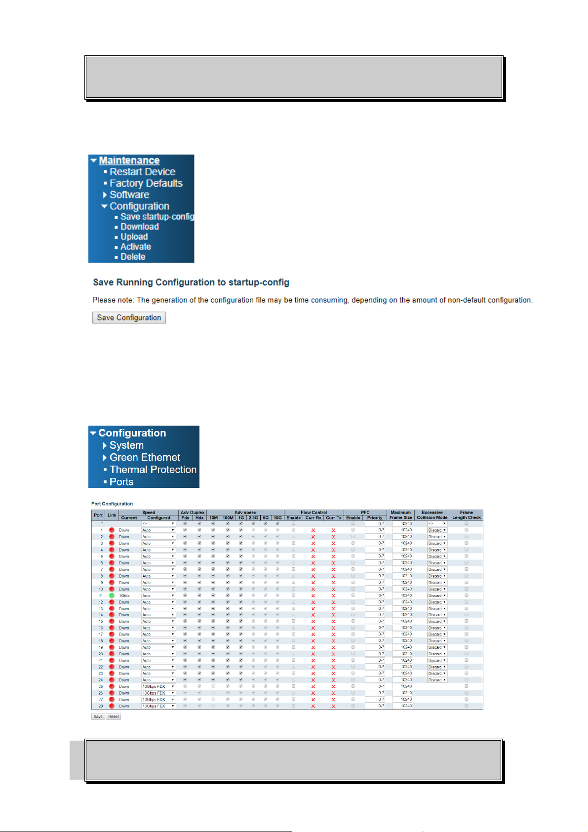
In the treemap below, expand the Maintenance Configuration Save startup-config
Click Save Configuration to save the configuration on start-up.
8.9 PORT SPEED SETTING
The port speed settings for the OSD2888 is auto mode for copper port and 10G for SFP port. On the
tree map below expand Configuration Ports.
PAGE 16
OSD2888 QUICK START GUIDE
DOC ID: 10118501
Page 17

OPTICAL SYSTEMS DESIGN
9 WARRANTY
Thank you for purchasing equipment designed, manufactured and serviced by Optical Systems Design
(OSD). OSD warrants that at the time of shipment, its products are free from defects in material and
workmanship and conforms to specifications. Our Warranty conditions are outlined below:
9.1 WARRANTY PERIOD
For warranty period, please call your local OSD distributor.
9.2 REPAIRS
Optical Systems Design reserves the right to repair or replace faulty modules/units. Please obtain a
“Return Material Authorisation” (RMA) form and number before returning goods.
Goods must be returned in adequate packing material to Optical Systems Design, Warriewood or its
nominated authorised representative, for all repairs.
9.2.1 WARRANTY REPAIRS
Return shipments to OSD shall be at customer's expense and freight back to the customer will be at
OSD expense.
9.2.2 OUT-OF-WARRANTY REPAIRS
OSD reserves the right to repair or replace any faulty goods. Freight costs and insurance for both
journeys are met by the user. All equipment repaired by OSD will have a 3-Month Warranty from the
date of dispatch.
9.2.3 SITE REPAIRS
By agreement site repairs may be undertaken for which out of pocket, hotel and travel expenses will be
charged.
9.2.4 EXCLUSIONS
This warranty does not apply to defects caused by unauthorized modifications, misuse, abuse or
transport damage to the equipment. All modifications to OSD’s standard product will need written
authorization and will be charged at normal repair rates. All modifications are to be carried out by OSD
Technicians. Warranty is void if unauthorized removal and/or tampering with serial number and/or
repair labels is evident.
PAGE 17
OSD2888 QUICK START GUIDE
DOC ID: 10118501
Page 18

OPTICAL SYSTEMS DESIGN
PAGE 18
OSD2888 QUICK START GUIDE
DOC ID: 10118501
Page 19

OPTICAL SYSTEMS DESIGN
PAGE 19
OSD2888 QUICK START GUIDE
DOC ID: 10118501
Page 20

Optical Systems Design Pty. Ltd.
7/1 Vuko Pl. Warriewood 2102
P.O. Box 891 Mona Vale
N.S.W. Australia 2103
Telephone: +61 2 9913 8540
Facsimile: +61 2 9913 8735
Email: [email protected]
Web Site: www.osd.com.au
OPTIC L
SYSTEMS
DESIGN
PTY LTD A.B.N. 83 003 020 504
Printed in Australia
 Loading...