

Page 1
Kezelési könyvKezelési könyv
Kezelési könyvKezelési könyv
High Definition
Digital Satellite Receiver
USER'S MANUALUSER'S MANUAL
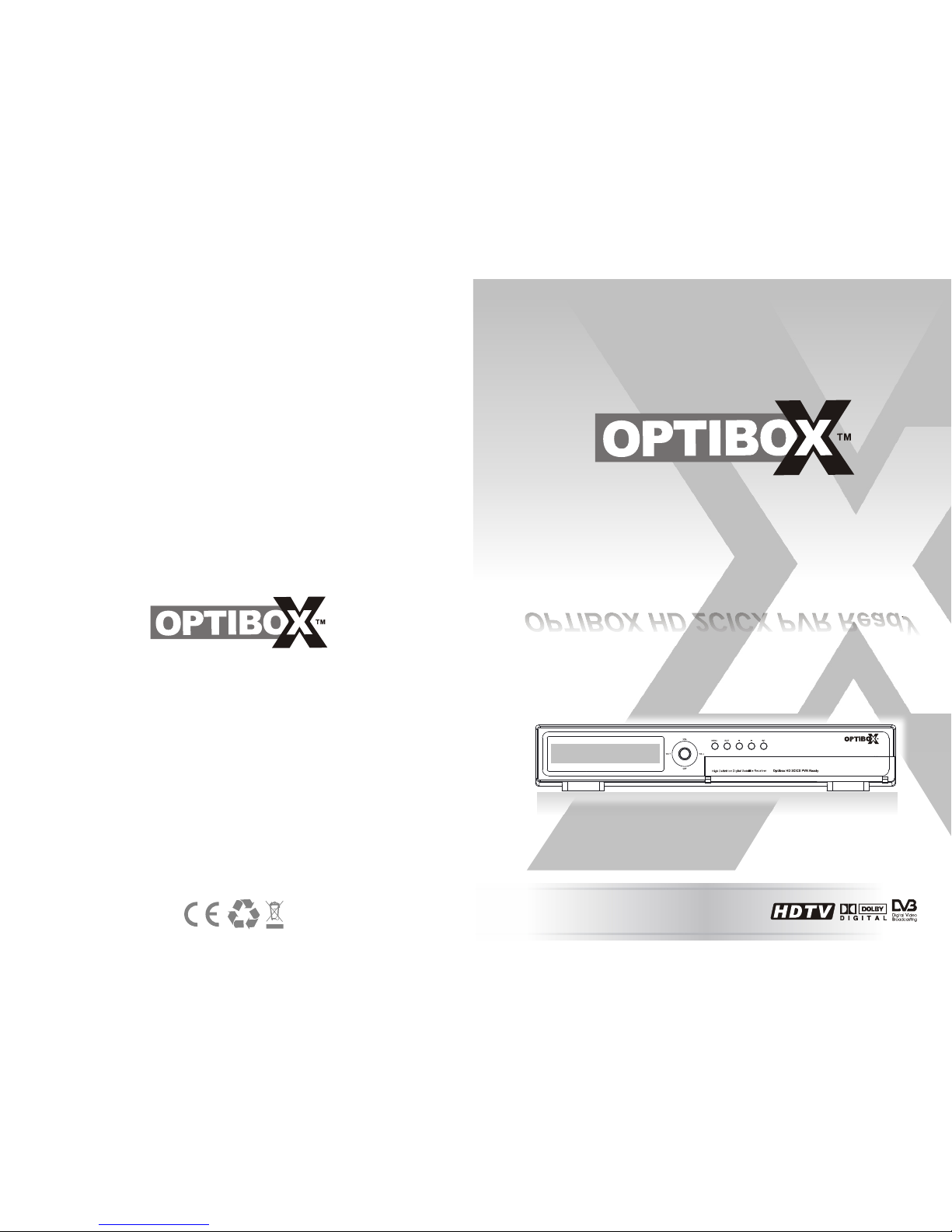
OPTIBOX HD 2CICX PVR Ready
USER'S MANUALUSER'S MANUAL
High D fin tion D gital Satellite R ce
ver
e i i e i
OK
Page 2

3
1. Features
A. Specifications………………………………………………………………………………...………….5
B. What's inside the package…………………………………………………………………………….....6
2. Hardware Controls
A. Front/Rear panel …………………………………………………………………………………….…..7
B. Remote controller…………………………………………………………………………………….….8
3. Connections
A. Connecting TV & Receiver…………………………………………………………………….………..9
B. Connecting to Dish …………………………………………………………………….………………12
C. Connecting to CI Module (CI Model Only) …………………………………………………………...14
D. Connecting to CA Module (CA Model only) …………………………………………………………14
4. Quick startl
A. Easy Install…………………………………………………………………….……………………….15
B. Easy Config…………………………………………………………………….………………………17
5. Software Operations
A. Basic Settings…………………………………………………………………….……………………18
B. System Setup…………………………………………………………………….………………….…22
C. System preferences …………………………………………………………………….………………24
D. CA…………………………………………………………………….………………………………..25
E. Channel setup…………………………………………………………………….…………………….26
F. USB Functions…………………………………………………………….……………….…………...27
G. Playing TV (or Radio) …………………………………………………………………….…………...32
Appendix
A. Trouble Shooting…………………………………………………………………….…………………35
B. Specifications…………………………………………………………………….…………………….35
C. Glossary of Terms…………………………………………………………………….………………..38
Page 3
4
Safety Instructions
1. Be sure to read this User's Manual before starting the operation of the receiver.
2. Never open the cover. It is dangerous to touch the inside of the receiver due to possible
electric hazard.
3. Remove the plug from wall outlet when you don't use this receiver for a long time.
4. Do not use a damaged power cord that may cause a fire or an electric shock.
5. Do not touch a power cord with wet hand. It may cause an electric shock.
6. Place the receiver in well ventilated and no-heat environment.
7. When connecting cables, the receiver must have been powered off.
8. Do not plug in/out CI module, when the receiver is powered on. But you can insert smart
card to CI module with powered on.
9. Do not stack the exposed firing device, such as candle, on top of the receiver.
10. Do not expose the receiver to dripping or splashing and that no objects filled with liquids,
such as vase, shall be placed on the apparatus.
11. The socket outlet shall be installed near the equipment and shall be easily accessible.
How to Use This Manual
This manual provides complete instructions for installing and using this receiver.
The following symbols will serve as follow.
Indicates a warning information.
Indicates any other additional or helpful information.
Page 4
1. Features
5
A. Specifications
Common Parts
Easy Graphic MENU Interface
RS232C Port for Updating Control Software and Additional Service
Supports DiSEqC1.0/1.2, 13/18V, 22Khz Tone
2-SCART Connectors & Composite video & Audio L/R output
1-Component video output (YCbCr output)
HDMI (High Definition Multimedia Interface) supported
Multi-language Function (Menu, Audio)
Last Channel Memory
OSD : Transparency & Blending, 256Palette Colors
Front Panel Buttons & IR Remote Controller User Interface
VFD (Vacuum Fluorescent Display)
Editing Functions (TV/Radio channel's name, Favorite name)
EPG for On Screen Channel Information
Memory for multiple satellite management (up to 64)
3 Operation Modes (Digital TV, Digital Radio, Favorite)
Digital Audio output (S/PDIF)
Support 8 Favorites
Digital Parts
Receives DVB-S1 QPSK, DVB-S2 QPSK, DVB-S2 8PSK Satellite Broadcasting RF Signal/Decodes the
Digitally Encoded Signal
Digital Tuner with Loop-through out
SCPC/MCPC Receivable from C/KU-band Satellite
MPEG-2 MP@ML, MP@HL & MPEG-4 part10 (H.264) Level 4
Teletext Supported Through & OSD
6000 Channels Memory
CI & Smart card Parts (pertinent models only)
DVB Common Interface (Viaccess, Nagra Vision, Conax, Irdeto, Cryptoworks, ASTON, etc)
SMART CARD Interface (CONAX)
Page 5
6
B. What's inside the package
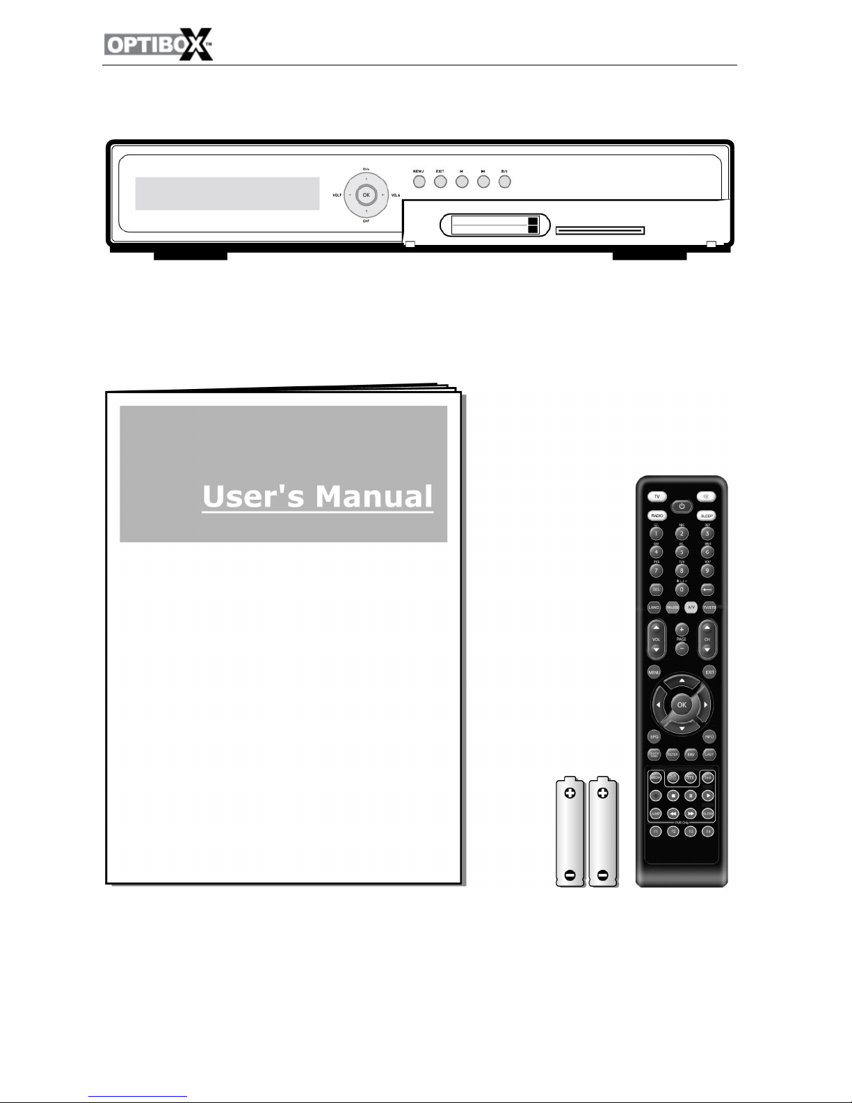
Satellite Receiver
User's Manual, Remote Controller, 2 of AAA Batteries
Page 6
2. Hardware Control
7
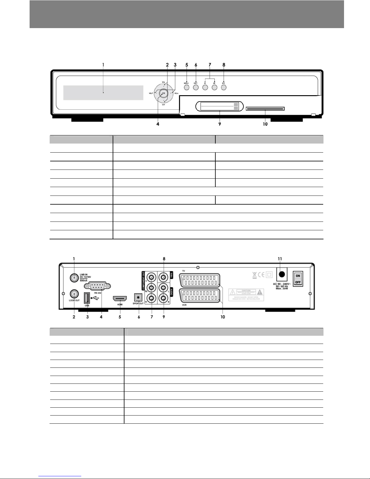
A. Front / Rear panel
Watching TV status (Live mode) OSD operating status (OSD mode)
1. VFD Display Shows information of selected channel, local time, system status, etc.
2. Channel +/- Change current channel. Move cursor up/down.
3. Volume +/- Increase/decrease volume levels. Change parameter value.
4. OK Shows channel list. Activates the highlighted menu item.
5. Menu Shows system setup software. Quits system setup software.
6. Exit Moves back from current menu or cancels the progressing operation.
7. Tab - Moves among menu items.
8. Power Turns the receiver on/off.
9. CI Slot Receives data from CI module for conditional access.
10. CAS Slot Receives data from Smart Card for conditional access.
11. Exit + Left Tab Change screen output mode. Current mode displays in VFD display screen.
Functions
1. LNB in Receives digital signals from satellite antenna.
2. Loop out Connects to extra receivers. (analogue or digital)
3. USB
USB 2.0 HOST / Connector: USB A TYPE / Current Consumption: Max. 500mA
4. RS232 Serial Port Receives new software from PC.
5. HDMI Sends HDMI signal to TV.
6. SPDIF Sends digital audio signal to audio amplifier.
7. Component Out Sends separated analogue signal to TV (Y, Pb, Pr connectors)
8. Composite Out Sends analogue signal to TV (Yellow connector)
9. Audio L/R Out Sends signal to audio amplifier (Red/White connectors)
10. Scart Connector
Upper connector sends analogue signal to TV. Under connector receives analogue
11. Power Cord Receives electric power. Check power specification. (See appendix B-6)
Page 7
8
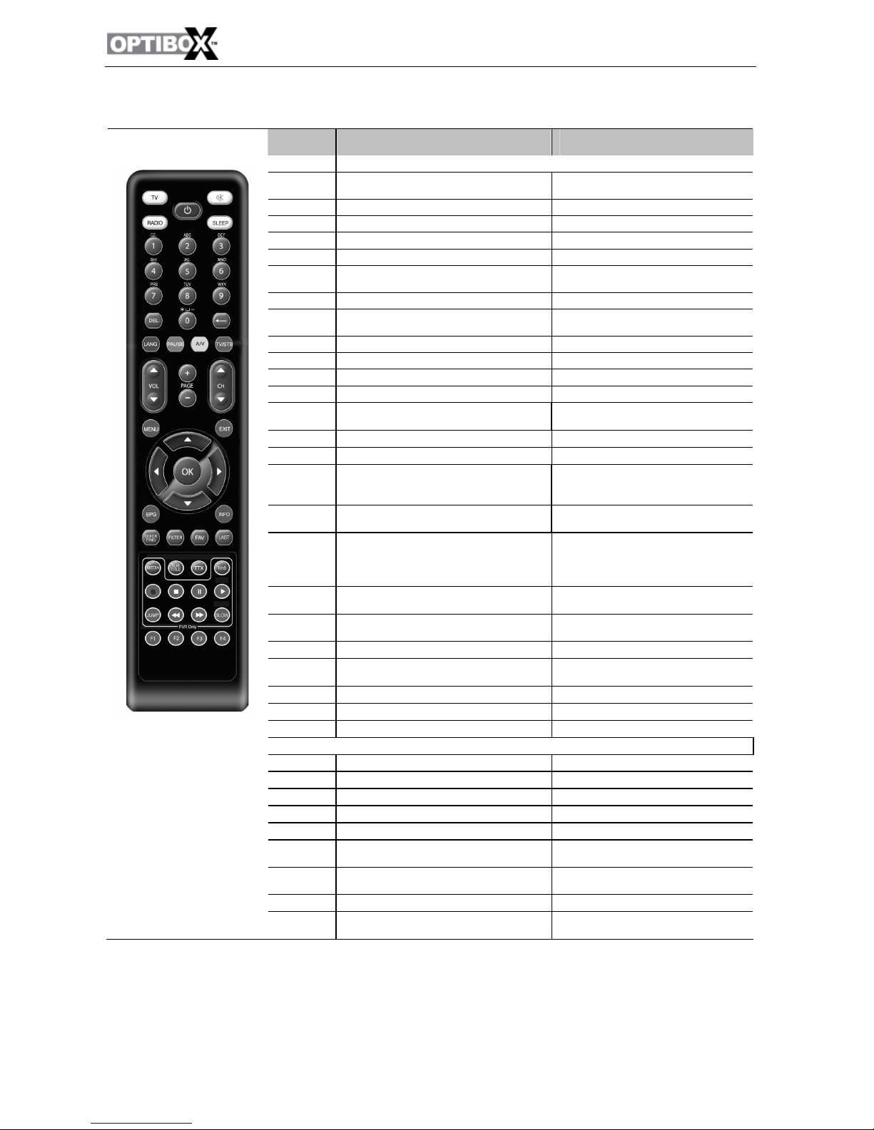
B. Remote controller
Buttons
Watching TV status
(Live mode)
OSD operating status
(OSD mode)
POWER Turns the receiver on/off.
1~0 Access specific channel directly.
Control numeric, alphabetic
operations.
MUTE Mutes audio output. TV Shows TV channel. RADIO Shows Radio channel. MENU Shows system setup software. Quits system setup software.
LANG
Shows list of the audio language
available in current channel.
Uses as a hotkey.
PAUSE Pauses video/audio output. Uses as a hotkey.
SLEEP
Shows sleep timer in 10 minute
increments.
EPG Shows program guide. -
▲▼ Change current channel. Move cursor up/down.
◀◀ Change volume strength. Change parameters.
OK Displays channel list. Activates selected menu item
EXIT -
Exits from menu or sub-menu.
Cancels the progressing function.
INFO Shows current channel's Information. -
FAV Shows favorite programs list. -
V +/- Increase/decrease volume.
Scrolls top level menu when cursor
is in sub-menu.
Go directly to next selection area.
P +/- -
Scrolls up/down a page in drop down
list.
FILTER
Directly go to channel filter menu.
(Same function of pressing yellow
button on channel list screen. Go to
page 27.
TTX
Shows the list of teletext languages the
current channel supports.
QUICK
FIND
Find channel from aplhabet input.
A/V Shows AV Menu
TV/STB
Switches between TV mode and STB
mode.
F1 / F3 Reserved.
F2 Shows available DVB Subtitle.
F4 Shows Channel Edit menu.
PVR FUNCTIONS
MEDIA Go to menu directly pvr record list
TMS Start the timeshift function.
RECORD Records the current program
STOP Stops recording or playing a program
PAUSE Stops and continue playing a program
PLAY
Play the recorded program or directly
show the pvr record list
<< >>
Rewinds/Forwards the recorded
program
SLOW Slow motion playback
JUMP
Jumps forward/backward to the
required location(5/10/20/30/60 min)
Page 8
3. Connections
9
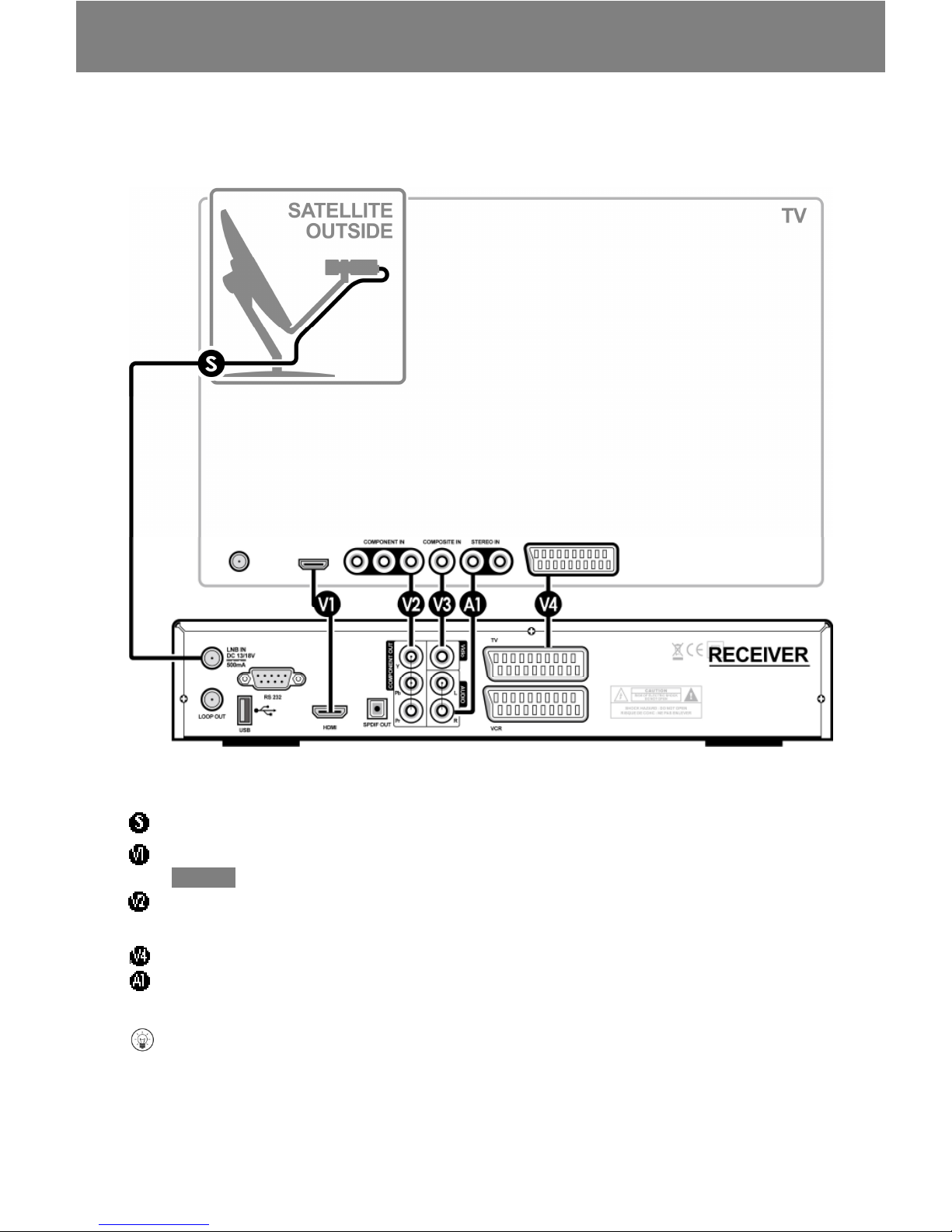
A. Connecting TV & Receiver
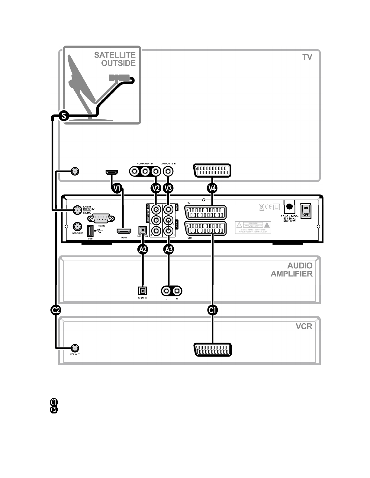
Connect between Satellite receiver & TV
Connect coaxial cable from LNB OUT (Satellite) to LNB IN (Receiver).
Connect HDMI cable from HDMI OUT (Receiver) to HDMI IN (TV).
Digital You can enjoy best video qualitiy with this connection.
Connect Component cable(3wires) from Component OUT (Receiver) to Component IN (TV).
Connect Composite Cable from Composite OUT (Receiver) to Composite IN (TV).
Connect Scart cable from TV Scart (Receiver) to Scart IN (TV).
Connect RCA cable (2wires) from Audio Out (Receiver) to Audio IN (TV).
Select one video connection type among V1~V4
Page 9
10
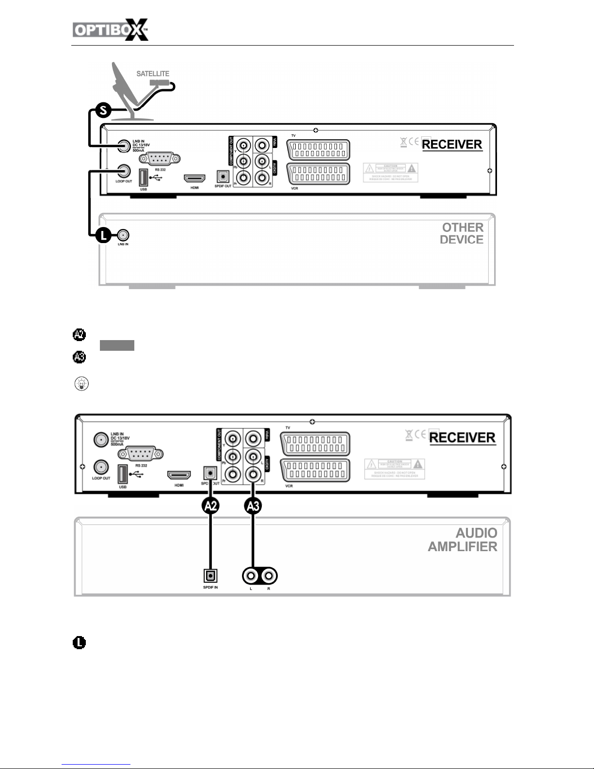
Connection between Receiver & Audio amplipier
Connect SPDIF Cable from SPDIF OUT (Receiver) to SPDIF IN (Audio Amplifier)
Digital You can enjoy best audio qualitiy with this connection.
Connect RCA cable (2wires) from Audio Out (Receiver) to Audio IN (TV)
Select one audeo connection type between A2, A3
Connection between Receiver & Other device using loop out connector
Connect coaxila cable from Loop OUT (Satellite) to LNB IN (Other device)
Page 10
3. Connections
11
Complexed connection between Receiver & TV & Audio amp & VCR
Connect Scart cable from VCR Scart (Receiver) to Scart IN (VCR)
Connect Coaxial cable from Antenna OUT (VCR) to Antenna IN (TV)
Page 11
12
B. Connecting to Dish
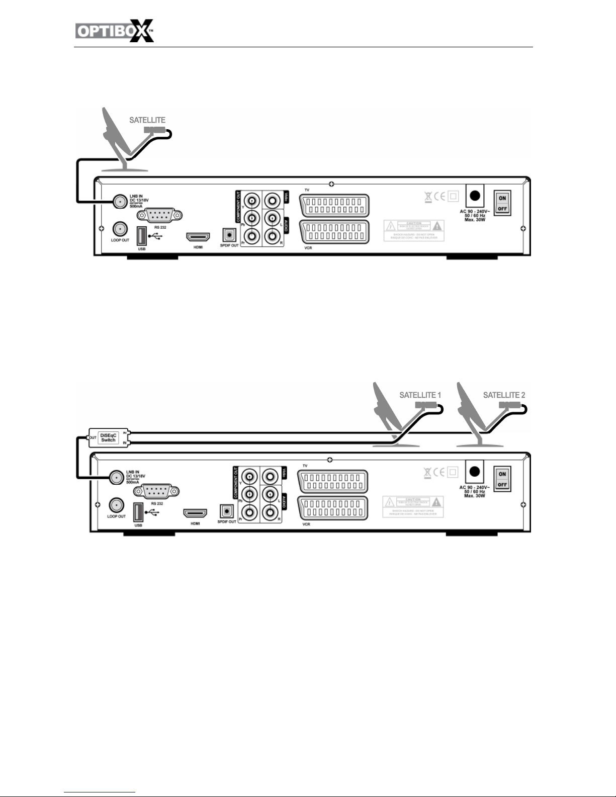
Fixed Single Satellite Connection
1. Aim your dish towards preferred satellite.
2. Connect coax cable from LNB/F to LNB IN of the receiver.
Fixed Multiple Satellites Connection
1. Aim your dishes towards preferred satellites.
2. Connect LNB/Fs to the inputs of Switch (DiSEqC)
3. Connect cable from Switch output to your LNB IN connector of the receiver.
Page 12
3. Connections
13
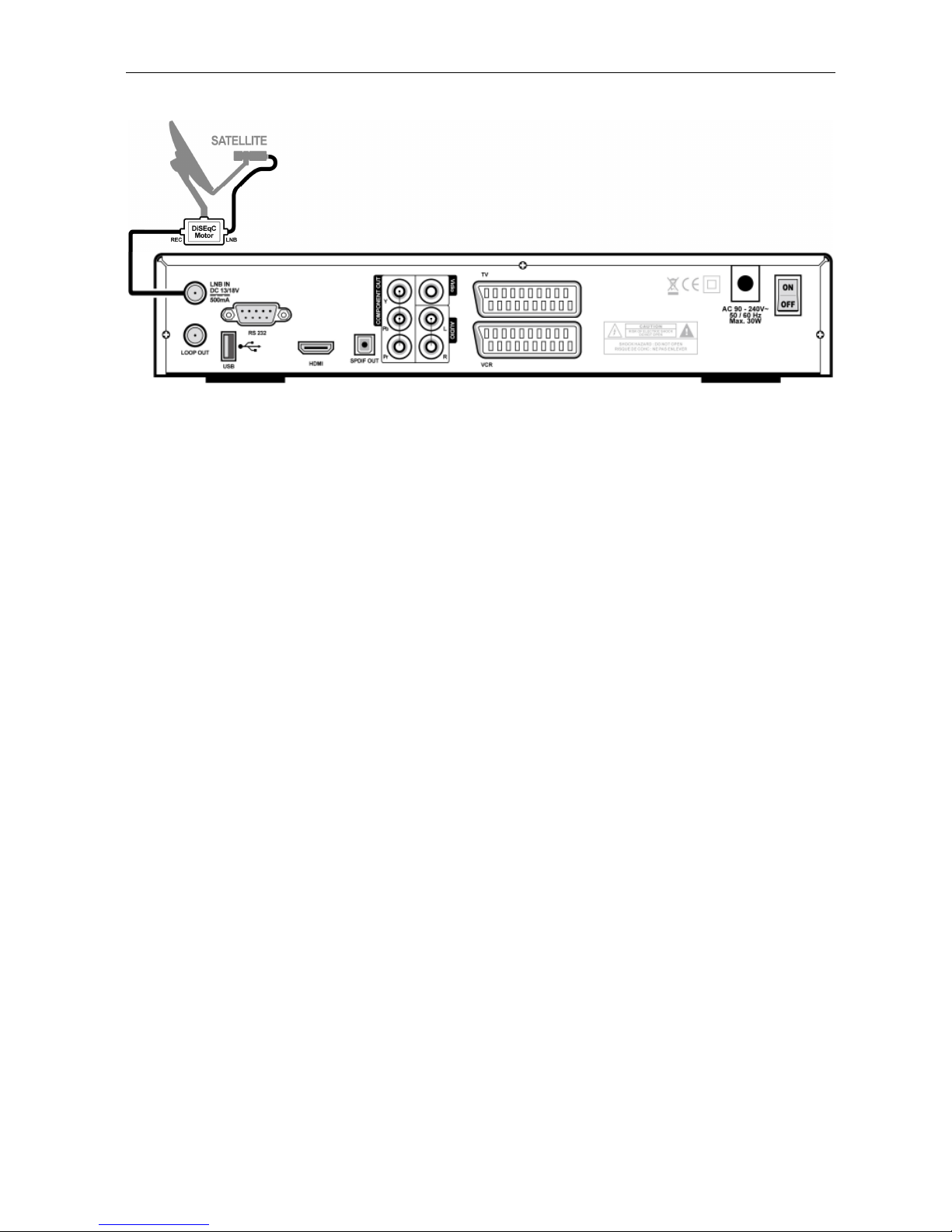
DiSEqC Positioner Connection
1. Aiming to TRUE SOUTH : Attach the antenna to the DiSEqC mount. Make sure it's at the center of the
mounting tube. Rotate the mount together with the antenna toward TRUE SOUTH. (Use a compass to
find TRUE SOUTH and calculate the magnetic offset)
2. Setting Elevation angle of the mount : Set the Elevation angle of the mount according to your
coordinates (Latitude). Refer Manufactures references to set the Elevation angle by the Elevation scale
on the antenna mount.
3. Setting Declination angle : Refer Manufactures references to set the declination angle by the scale on
the antenna mount.
4. Connect the coax from LNB/F to DiSEqC positioner, and from positioner to LNB IN of the receiver.
Page 13
14
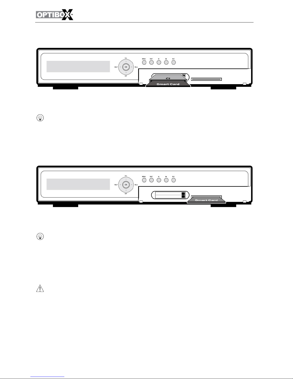
C. Connecting to CI Module (CI Model Only)
Insert CI module into CI slot for watching TV program from Service Provider.
This CI can be use only SAT program.
D. Connecting to CA Module(CA Model only)
Insert Smart Card into Smart Card slot for watching TV programmes from Service Provider.
This CA can be use both of Terrestrial and SAT program.
Do not plug in/out CI module when the receiver is powered on.
CI module is already attached to receiver, you can plug in/out smart card with power on status
Page 14
4. Quick Start
15
Easy Install & Easy Config shows most necessary processes to see TV quickly and easily.
At the first time you power on (or after Factory Reset), these features will be displayed.
A. Easy Install
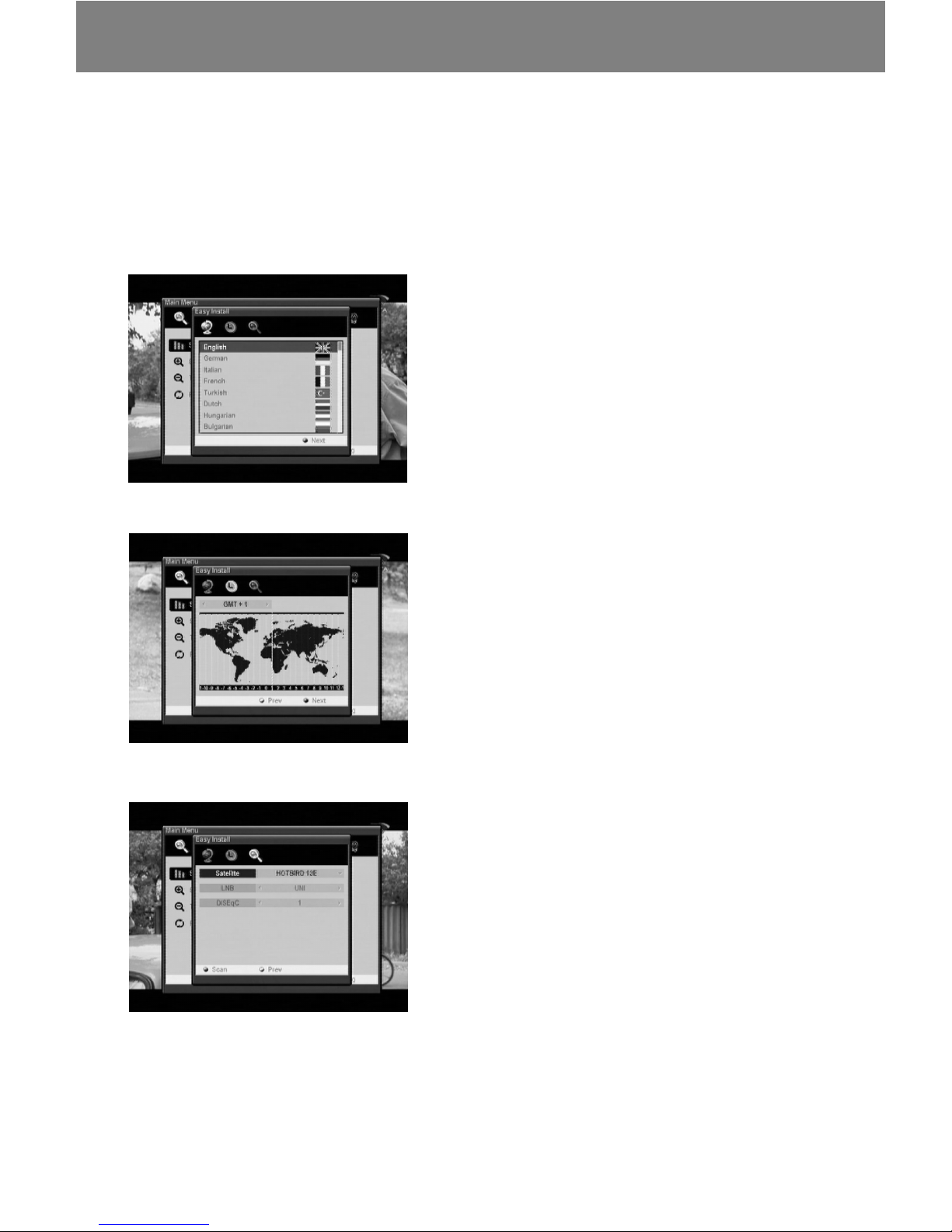
Press Red button to enter EZ Install menu and is started. Ez Install has three steps below.
1. Select Language
If you select language you can view menu and massages as
your favorable language.
If you press UP-DOWN button you can select language for
your convenience.
Press Next(Yellow) button when the selection is completed.
2. Select Region
In this menu if you select favorite region, Sat List will show
you regional list as you select.
If you press LEFT/RIGHT button you can select Region for
your convenience.
If the selection is completed press Next(Yellow) button, if
you want to go to previous menu press Previous(Green)
button.
3. Select Satellites
Select satellites, LNB, DiSEqC for your convenience.
In order to scan, press Scan(Red) button.
To go to previous menu press Previous(Green) button.
Page 15
16
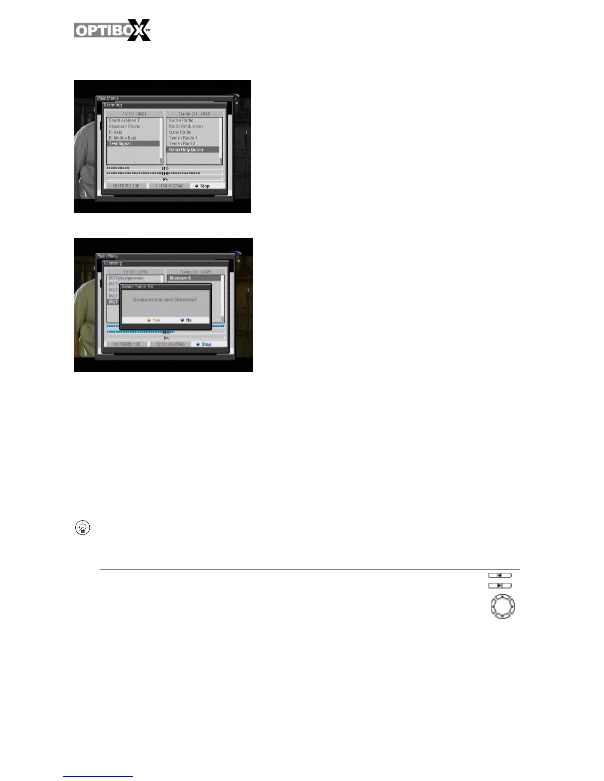
3-a. Scanning channels in satellite you selected.
3-b. Press Yes button if correct channel list appears.
Before Settings
Make sure you connected lines between Satellite and Receiver and TV correctly.
Turn on your TV and receiver.
Press menu button on Remote Controller to display main menu.
You can navigate menus using Tab buttons on the front panel.
You can navigate sub menus under selected main menu using Arrow buttons
on the remote
controller.
Page 16
4. Quick Start
17
B. Easy Config
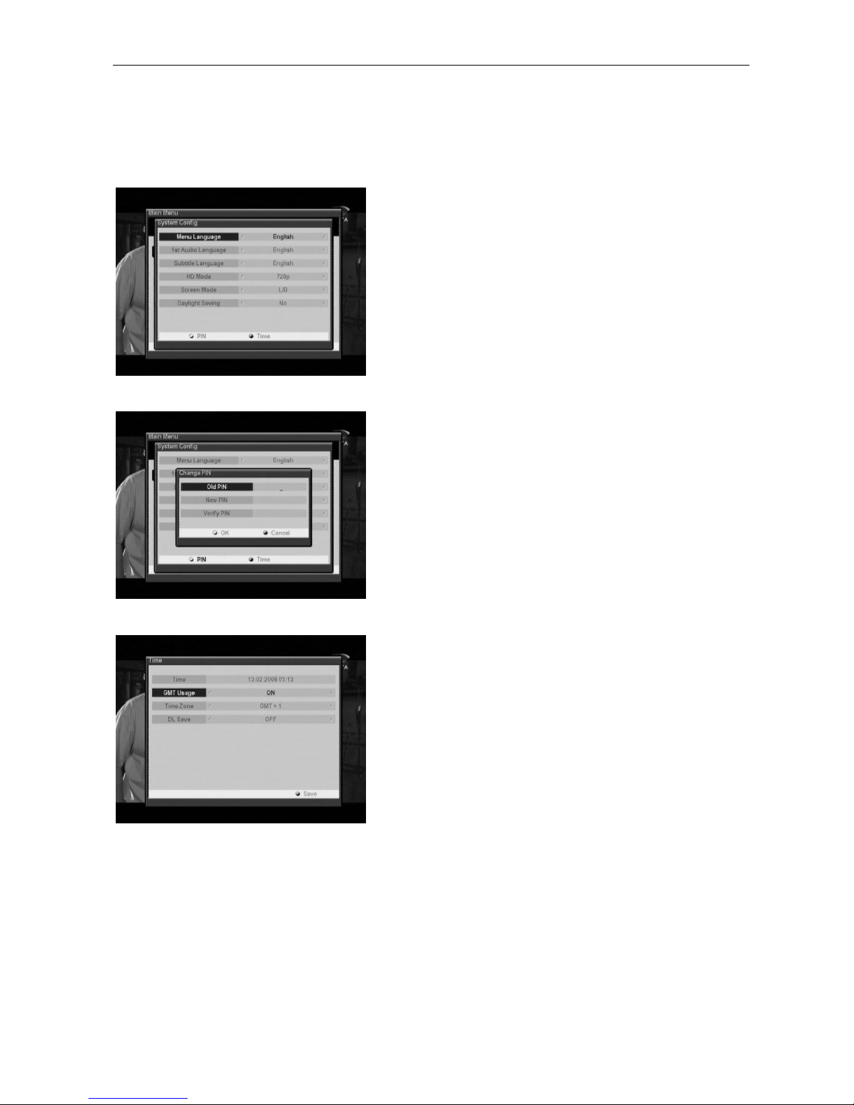
Press blue button to enter EASY Config Menu.
1. Setup main menu.
Menu Language : Select the language for software menus.
1st Audio : Select the language for audio in broadcast.
Subtitle Language : Select the language for subtitle.
HD Mode : Select HD Mode between 576p, 720p, 1080i.
Screen Mode : Select screen mode(Letter Box, Full Screen)
Daylight Saving : Select to use daylight savings or not.
2. Press PIN button to setup password.
3. Press Time button to setup time.
Page 17
5. Software Operations
18
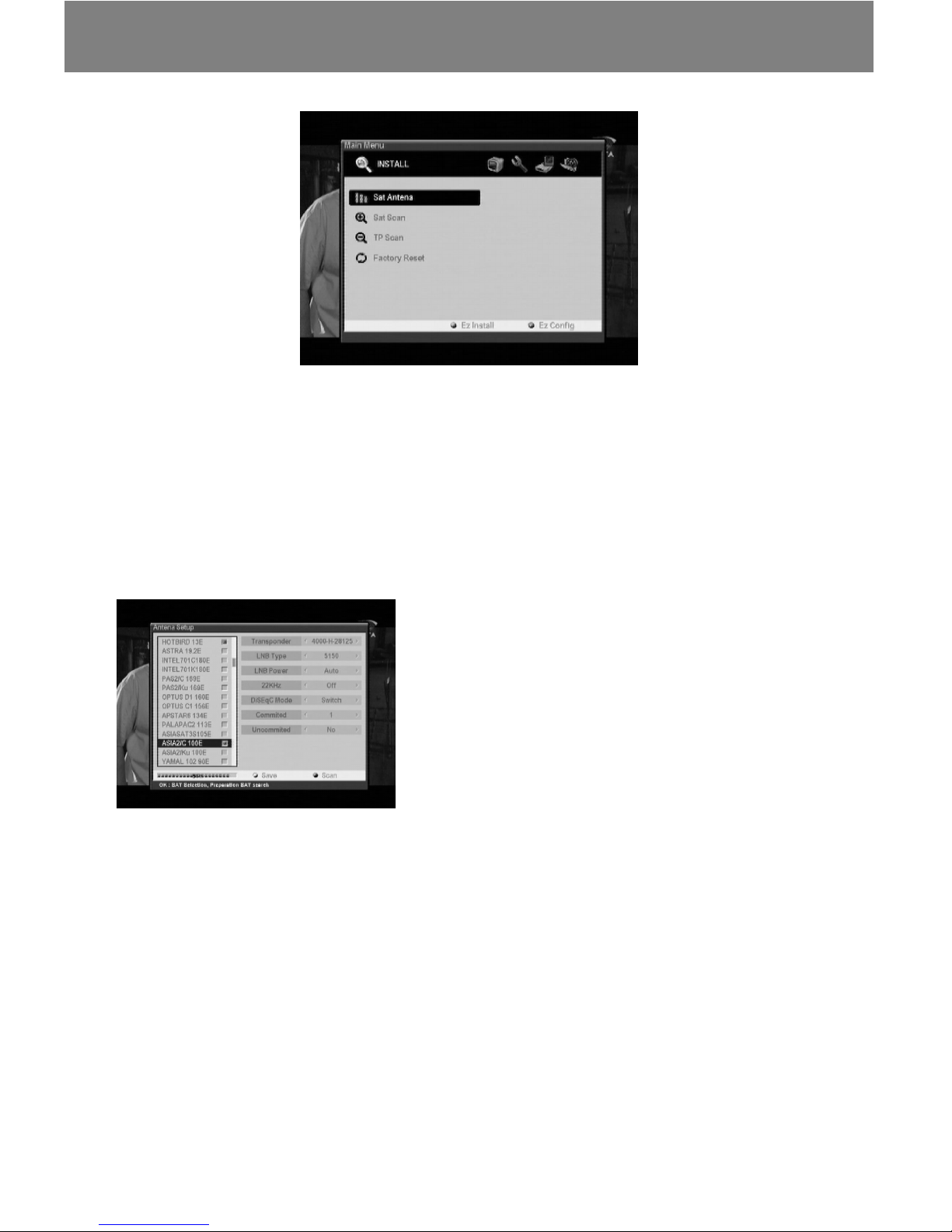
OSD software consists of main-menu and sub-menu, as you see in the screen above.
Main-menu has 5 items. Each main-menu item has its sub-menu items.
Our software has 3 blocks.
Leftside block is top level menus. (INSTALL, SYSTEM, PREFERENCE, CA, CHANNEL),
Rightside block display sub-menus which is included main icons of each top window.
Functions under sub level menu appear in popup windows.
A. Basic settings
Sat Antenna
With this menu, you can select th
e satellite and set antenna
to search channels. There are up to 64 satellites available.
1. If you press OK at Sat Antenna menu in Install in Main
Menu, the <Sat Antenna> will appear.
2. Use the Up/Down button to select the item, and set up the
parameter with the Left/Right button.
3. If you have completed the setting, use Save(Green) button
to save, Scan(Yellow) button to scan.
Page 18
5. Software Operations
19
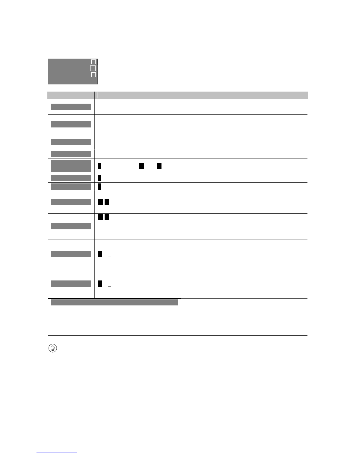
Elements for antenna setup menu
HOTBIRD
ASTRA 19E
INTEL70 1/C
…
Satellite list
Move the cursor to a satellite and press OK to select the satellite or press
EXIT on the remote controller to go back.
If you press F1 BUTTON on remote control, you can move to SAT LIST directly.
If you have connected to a dual LNB or two antennas connected to a 22KHz tone switch box, set it to "ON".
If you had set LNB Type to Universal, LNB Power and 22KHz switch options are disregarded.
If you set LNB Dish to Moved, DiSEqC switch is disappeared and positioner item is appeared.
On the other hand, if you set LNB Dish to Fixed, positioner item is disappeared and DiSEqC switch is appeared.
Universal LNB : 9750 ~ 10600M.
Sub Menu Parameters Function / Tips
Transponder 12610-V-22000 / …
Select Transponder which you want to test
current signal quality.
LNB Type
UNI / WIDE / OCS C-BAND /
5150 / 9750 / 10000 / 10050
/10600 / 10750 / 11200 / 11475
You can select one of the LNB type menu
UNI band width : 9750~10600
LNB Power
Auto / 13V(for V signal) /
18V(for H signal) / Off
Select between vertical and horizontal signal.
13V is for V signal, 18V is for H signal
22KHz Auto / Off / On
Setup the 22KHz switch.
DiSEqC
Mode
Switch(default), Motor, USALS
You can set dish's direction from Sat Antenna
menu.
Committed S NO / 1 / 2 / 3 / 4
To use the DiSEqC switch, set up DiSEqc.
Uncommitted S NO / 1 / 2 / 3 / 4
Set Uncommitted DiSEqC.
Move M U EAST / STOP / WEST
While pressing left direction button (◀) on
remote controller, dish rotates to east. Pressing
right direction button (◀), dish rotates to west.
Command
M U Goto Center / Step East /
Step West / Goto E Limit /
Goto W Limit / Set E Limit /
Set W Limit / Clear Limits
Set dish position’s East or West limit, disable
limit value. Change item with Left/Right button
and press OK button to set/disable limit value.
Latitude U 000.00
Set Antenna’s Latitude and Longitude
Put digit directly from remote controller.
Press OK to turn direction from North/East to
South/West
Longitude U 000.00
Set Antenna’s Latitude and Longitude
Put digit directly from remote controller.
Press OK to turn direction from North/East to
South/West
0~100
%
If dish position is moved to the correct position
to receive satellite signal, signal level and
quality color changes(for example to Green), To
save current dish position use Save button
(GREEN).
V
Page 19
20
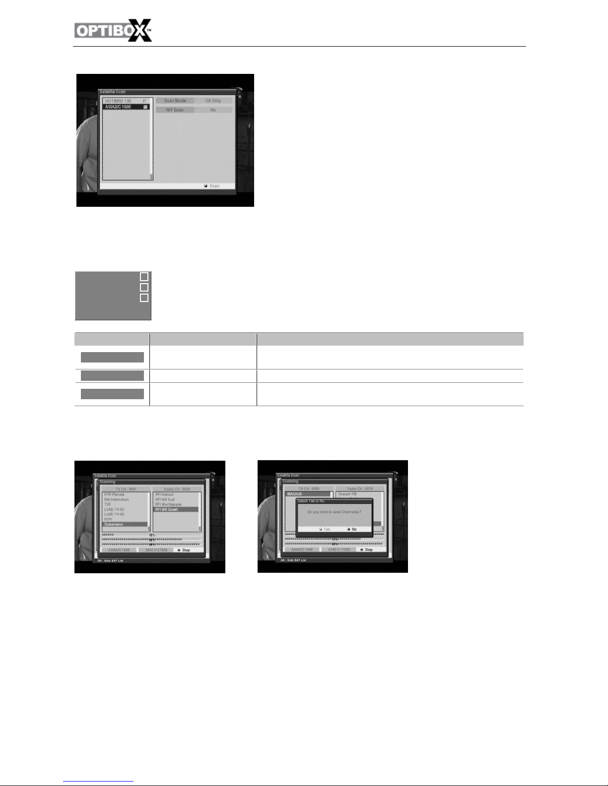
Sat Scan
In this menu you can search for specific TPs.
If you h
ave already set the Antenna set up, you can scan the
satellite. In this menu, there are Scan Mode, Network
search and Radio.
If you press OK in Sat Scan button, the <Satellite Scan> will
appears.
Use the Up/Down button to select the item, and set up the
parameter with the Left/Right button.
If you have completed setting, use Scan(Yellow)
button
to scan.
Elements for Satellite Scan menu
HOTBIR
ASTRA 19E
INTEL701/C
…
Satellite list
You can s
elect other satellite to scan channels using UP/DOWN or satellite list(If
you press OK button, then the satellite list will be selected).
Sub Menu Parameters Function / Tips
Scan Mode
Free+CA / Free Only /
CA Only
You can designate scanned channel type
Radio CH
Yes / No You can select Radio channel scan or not.
NIT Scan
Yes / No
You can select Network Information for added scan from
the Stream or not.
If you press Yellow(Scan) button, all transponders of current satellite are scanned.
Scanning transponders in satellite
you selected.
Press Yes button if correct transponder
list appears on screen.
V
Page 20
5. Software Operations
21
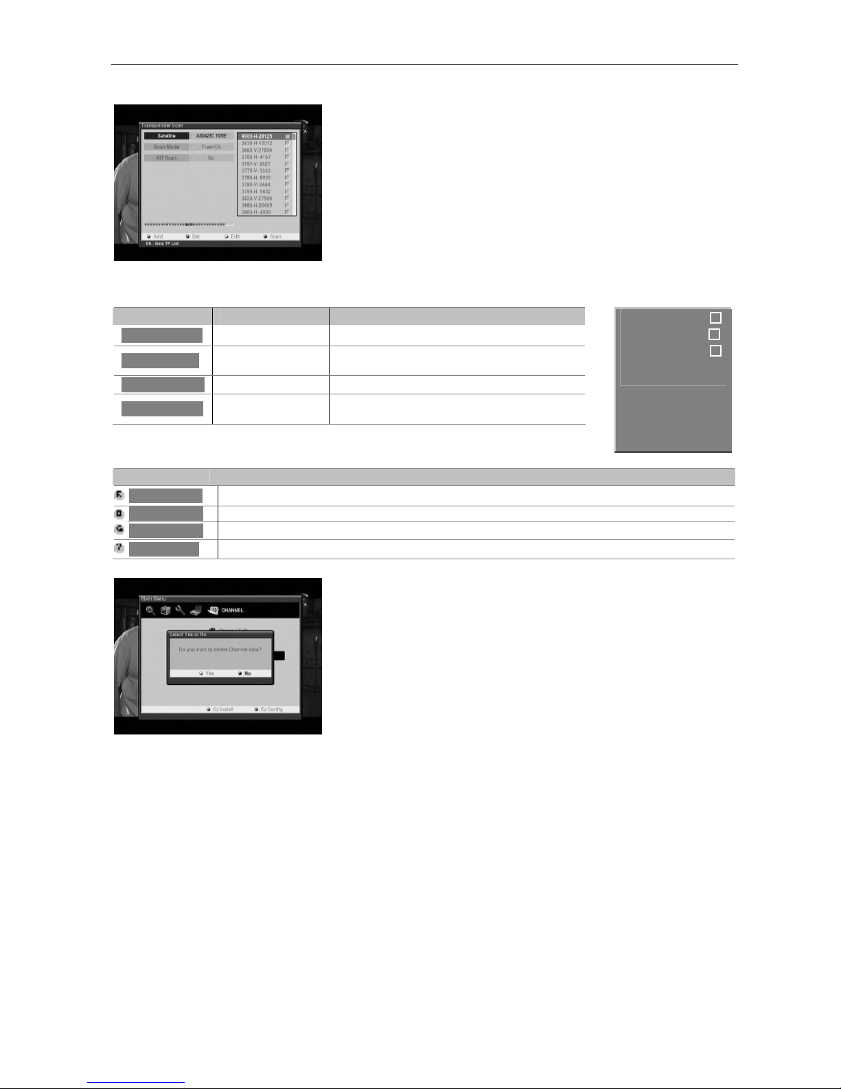
Transponder Scan
1. If you press OK in TP Scan button, the <Transponder Scan> will
appear.
2. Use the Up/Down button to select the item, and set up the
parameter with the Left/Right button.
3. If you have completed setting, use Yellow(Scan) button to scan
current transponder channel, Red(Add) button to add TP,
Blue(Del) button to delete TP, Green(Edit) button to edit TP
information.
Elements for Transponder Scan menu
10719-V-27500
10723-H-29900
10758-V-27500
…
Buttons Function / Tips
Add Add new TP by setting Frequency, Polarization, Symbol Rate.
Del Delete selected TP.
Edit Edit the TP by setting Frequency, Polarization, Symbol Rate.
Scan Edit the TP value. The Modify item to change the current value.
Factory Reset
Deletes all the data currently saved and returns the system to the
Factory Default status.
Sub Menu Parameters Function / Tips
Satellite Satellites list View satellites selected in Sat Antenna menu.
Scan Mode
Free+CA / Free
Only / CA Only
Designate scanned channel type
Radio CH Yes / No Select radio channel scan or not.
NIT Scan Yes / No
Select network information for added scan
from the stream or not.
V
Page 21
22
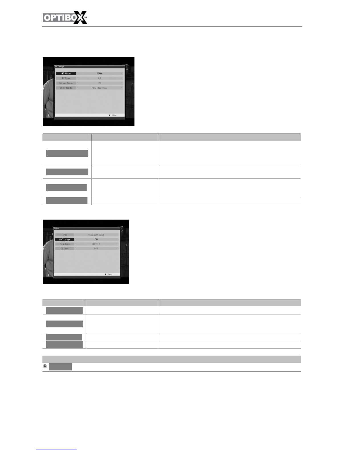
B. System setup
TV Setup
Set the TV output according to selected channel source.
Sub Menu Parameters Function / Tips
HD Mode 720p / 576p / 1080i
You can select OSD & video display mode to one of Multi,
PAL, NTSC. When PAL mode is selected, for example All
screen is displayed as the PAL mode in spite of the current
Programs transmission mode.
TV Type 4:3, 16:9
When program transmission is in 16:9 and you have a TV set
with the 4:3 picture format.
Screen Mode
L/B, FF, P/S CCO, P/B,
FF
When program transmission is in 16:9 and you have a TV set
with the 4:3 picture format you can select Full screen or Letter
Box picture format.
SPDIF Mode PCM, On(Dolby), Off
Select audio output type.
Time
If a broadcaster provides GMT, you can set the time using GMT,
or set your own time by yourself.
GMT usage is on, current time is automatically received from
satellite and you only need to set the time zone.
GMT usage is off, "Set Data" and "Set Time" menus will be
displayed.
Sub Menu Parameters Function / Tips
Time yyyy:mm:dd hh:mm
It shows current Time.
GMT Usage ON, OFF
GMT is the standard time from Satellite.
If GMT is off, you can input date time manually.
If GMT is on, it is the Time in the stream.
Time Zone GMT+0 ~ +12, -1 ~ -12
It sets Time zone in GMT.
DL Saving OFF, ON
It set Summer Time.
Buttons Function / Tips
Add Save time settings
Page 22
5. Software Operations
23
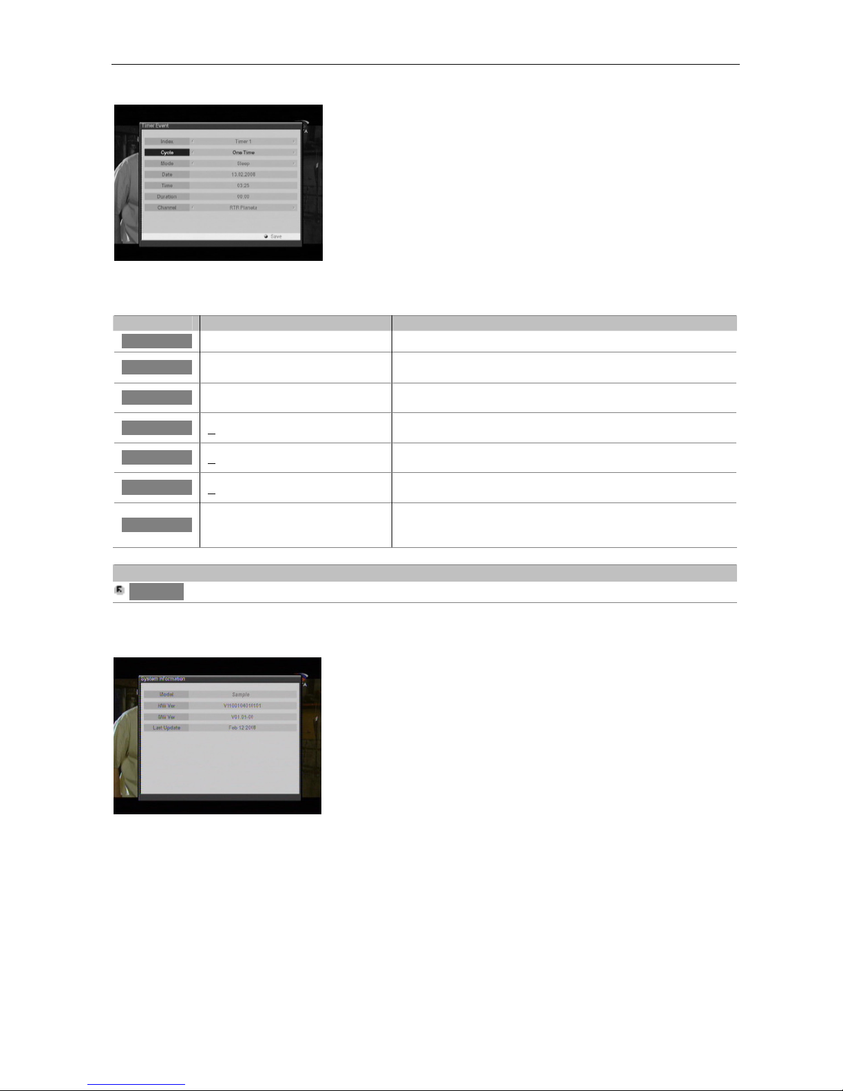
Timer
You can set the time to make the receiver perform the designated
actions including timer based and turn on/off the set-top-
box
with Wake Up/Sleep function.
Sub Menu Parameters Function / Tips
Index Timer 1~8
You can select up to 8 timers.
Cycle
Off, One time,
Every day, Every week
You can set the cycle of the action designated in the timer
mode.
Mode Sleep, Wake up, Duration
You can set the mode of the action designated in the timer
mode.
Date 0000.00.00
You can set the starting date of the timer action. If you press
OK calendar is displayed.
Time 00:00
You can input the time. If you press OK Clock Setup is
displayed
Duration 00:00
You can input the Duration time. If you press OK Clock Setup
is displayed.
Channel
You can select the program Channel viewed when receiver is
powered on by the wake up timer function. If you press OK
Quick Find is displayed
Buttons Function / Tips
Add Save Timer settings
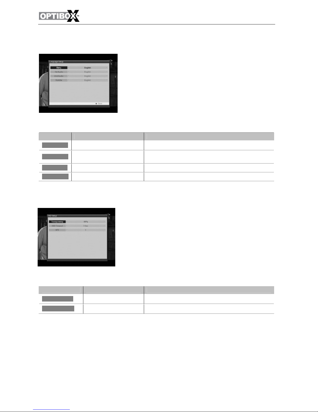
System Information
Shows the system informat
ion including Model number, H/W
Version, S/W Version, Last Update, Boot Version.
Page 23
24
C. System preferences
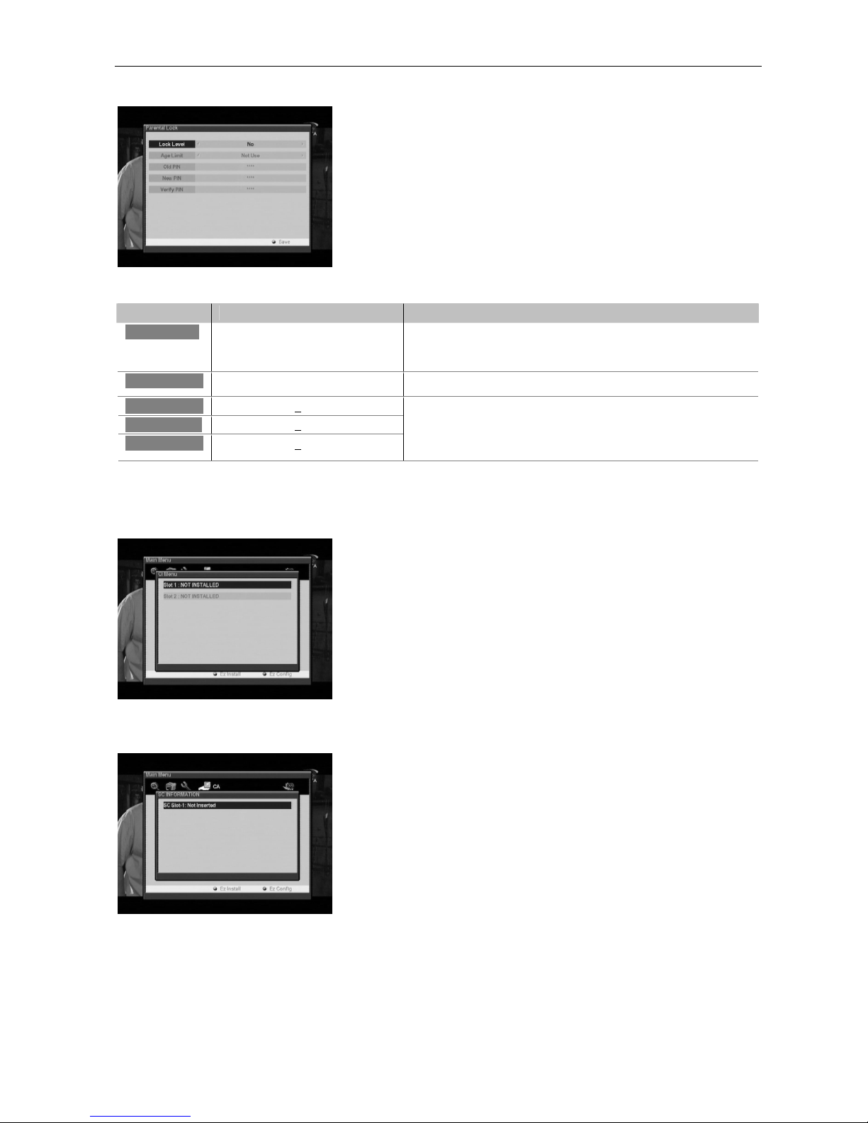
Language setup
You can select OSD menu language, Audio language and subtitle
language.
Use the Right or OK button to view language list.
Sub Menu Parameters Function / Tips
Menu Languages available. Set language which indicates Ul and messages.
1st Audio Languages available.
Set language which you want to displayed first in the Audio
language.
2nd Audio Languages available. Set language in case of no 1st audio in the Audio language.
Subtitle Languages available. Select Subtitle language for your convenience.
Sub Menu Parameters Function / Tips
Transparency 10 ~ 100% Set transparency of the window.
OSD Timeout 1~10 sec, ON Set time in the information bar and volume bar.
OSD setup
You can change menu concept for your convenience like color
schem, transparency, brightness and window size.
OSD Timeout is the duration time of information bar and volume
bar.
Page 24
5. Software Operations
25
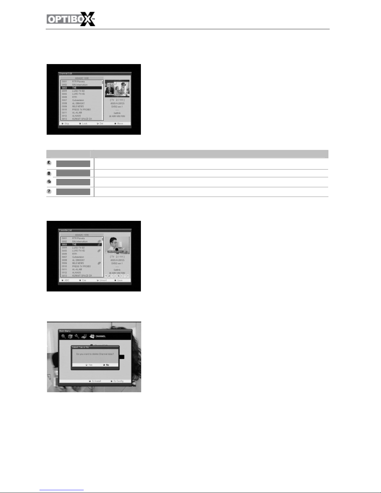
Prental Lock
Changes the Personal Identification Number(PIN) which is used
to control the access to the receiver and individual channel.
Sub Menu Parameters Function / Tips
Lock Level No, Install, Menu No : Do not use Parental Lock.
Install : Lock to enter Install menu.
Menu : Lock to enter Software setup.
Age Limit Not use, Every, PG 4~18 Require PIN code to view channels over limitation.
Old PIN ****
New PIN ****
Verify PIN ****
To change the PIN(password consist of 4digits),
Input the old PIN, Input new PIN, Re-input new PIN to
confirm, Save the PIN configuration using save button.
Default PIN code is 0000 (4 zeros).
D. CA
Common Interface
You can navigate the menu, which is provided by CI Module.
This information varies and depends on the service provider.
Conax
You can navigate the menu, which is provided by smart card.
This information varies and depends on the service provider.
Page 25
26
E. Channel setup
Channel Edit
You can set channel as your favor.
Buttons Function / Tips
Skip Skip this channel when scrolling with channel +- buttons.
Lock
Lock this channel for a password.
Del
Remove this channel from list.
Move Move up, down in channel list.
Favorite Channel Edit
You can select 8 channels to set as Favorate channel.
To set
1. Select a channel to set favorate.
2. Press OK to preview screen.
3. Press 1~8 to set address of favorate channel.
To release
1. Highlight a channel to release.
2. Press that channel's favorate address number.
Reset Channel
Deletes only the saved channel data, other setting values are not
deleted.
Page 26
5. Software Operations
27
F.USB FUNCTIONS
USB Device Connection
Connect to USB Device( USB HDD, USB Memory )
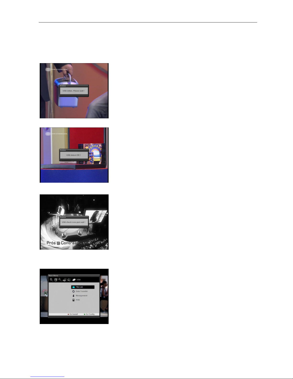
You can see the Message "USB initial.. Please wait!"
If the file system was FAT, you can see the message "USB detect
OK!"
If the file system was NTFS, USB Device will not be connected. You
can see the message "USB check FAIL!"
We don,t support the NTFS file system to our the set top box.
USB MENU - File List
Menu -> USB -> File list
Page 27
28
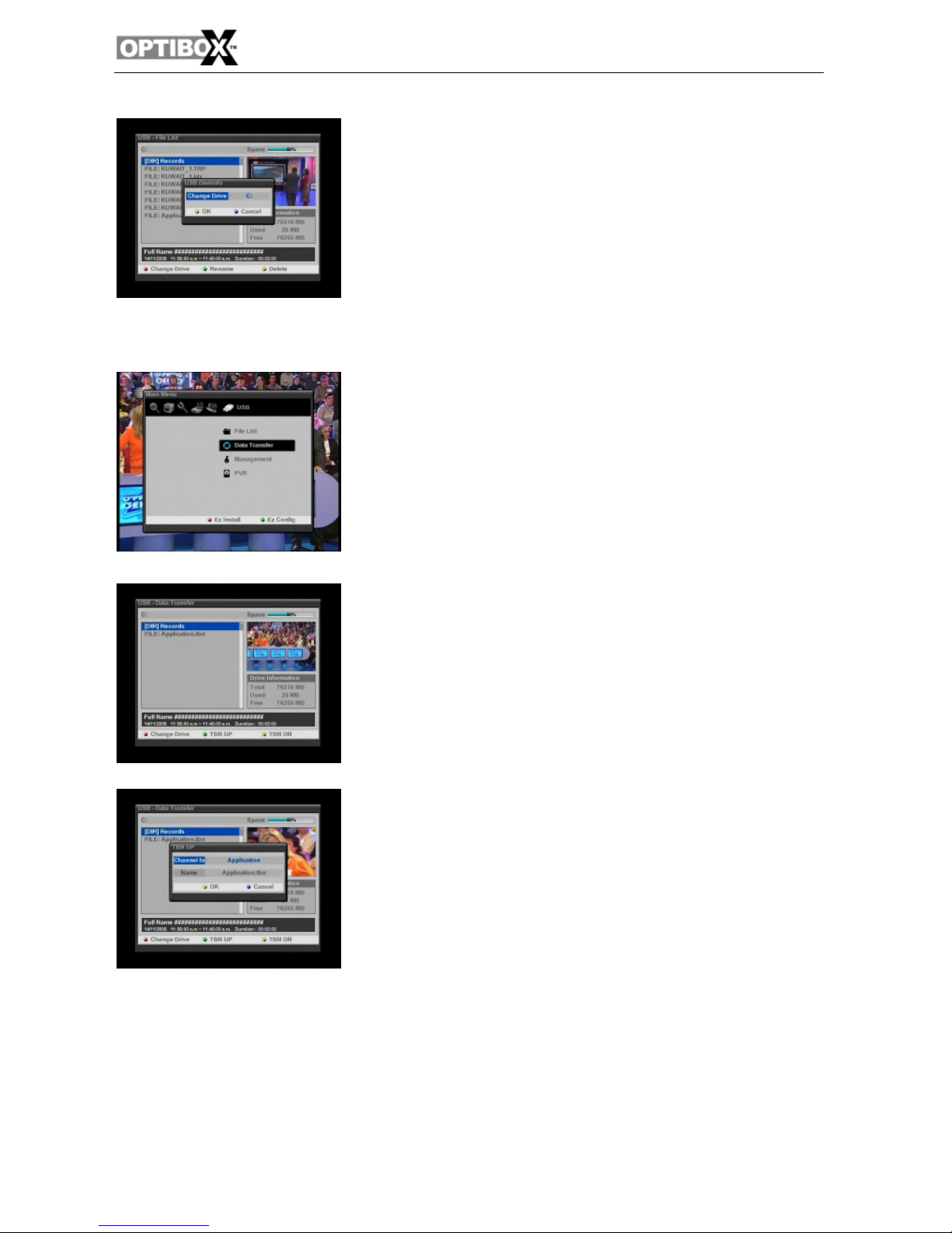
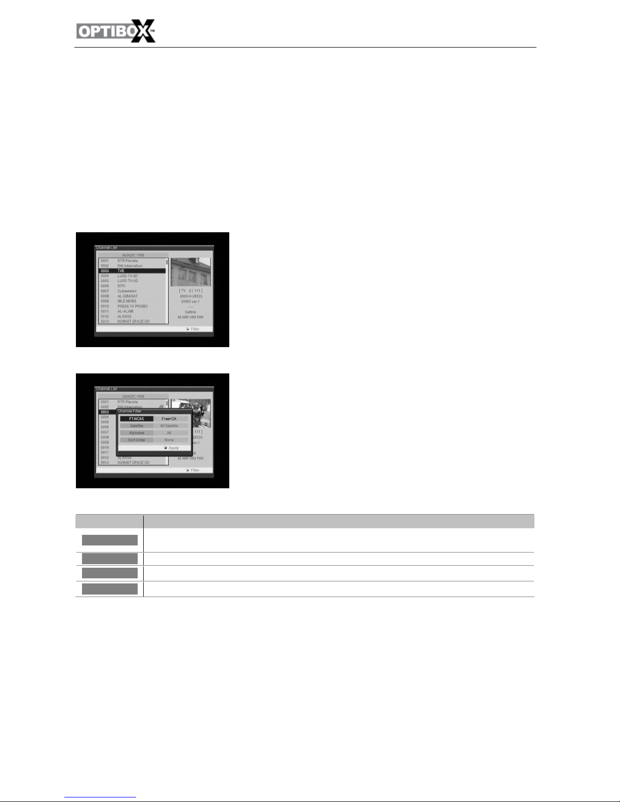
You can check the file list in USB Device.
· RED button is used to change drive.
· Green button is used to Change the file name
· Yellow button is used to delete the file.
USB MENU - Data Transfer
Transfer with STB to USB Device( Application / XKey / Channel /
All Data )
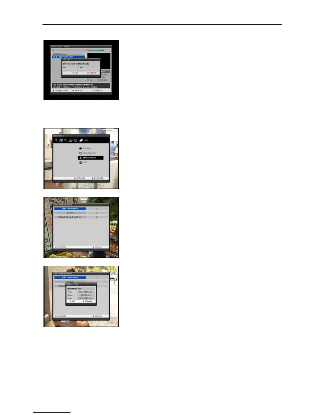
You can see the “*.tbn” file
To Change Driver , press the Red buttonYou can transfer the data
from STB to USB when the Drivers are over than one.
To upload tbn file , press the Green button .
Page 28
5. Software Operations
29
· to *.TBN download, press yellow button, then you can see "Do you
want to Download?" window.
If you select the OK, STB will start to download from USB to set top
box.
USB MENU – Management
USB Device Management
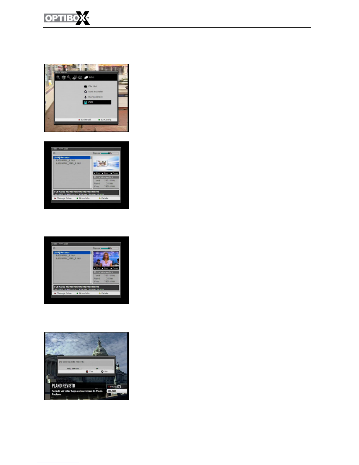
Disk Information / Format / Default Recording Driver
Disk Information( Menu or Red button )· You can check the USB
Device’s information
Page 29
30
USB MENU – PVR
Play the file in USB Device
Recording
USB Device file list
Normal Recording
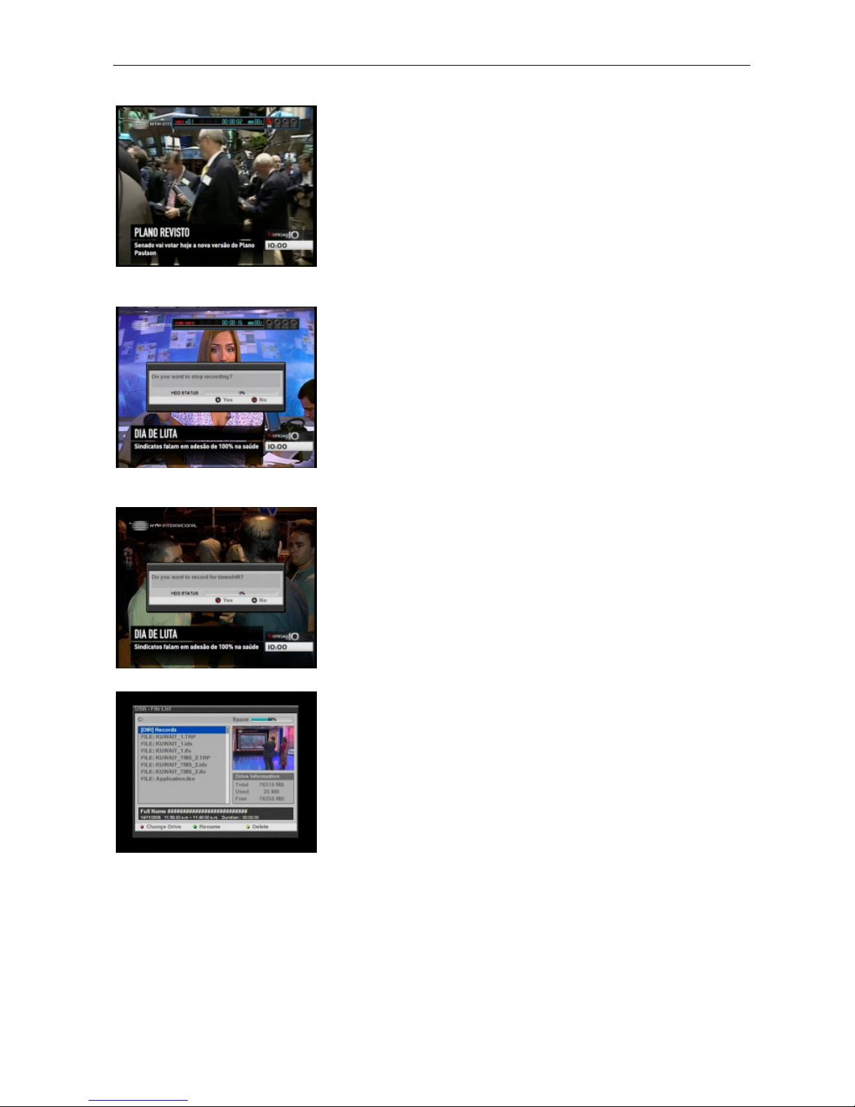
This function is used for recording a program while watching it by
applying the following steps :
1. Press the record button on your remote control for recording.
You can see the “Do you want to record?”window on the screen.
2. To start recording ,if you want to select YES, press the Record
button again.
To cansel start recoding , if you want to select NO,press stop
button .
Page 30
5. Software Operations
31
Now STB is Recording the current program.
To stop recording .
You must press the stop button of remocon, then you can see “
Do you want to stop recording ?”.
to select YES , press the stop button again .
to select NO , press the record button.
Time Shifting
To start time shifting , press the TMS button ,
You can see the left fiqure , if you want to YES, press REC button ,
but if you want to NO, press STOP button.
File list in USB Device after the recording
Page 31
32
G. Playing TV (or Radio)
In live mode, various menus are displayed on the screen with remote controller action.
You can change the current status and mode with various buttons including the Up/Down, SAT, INFO
and EPG.
You can see the banner contains channel information when you press the INFO button.
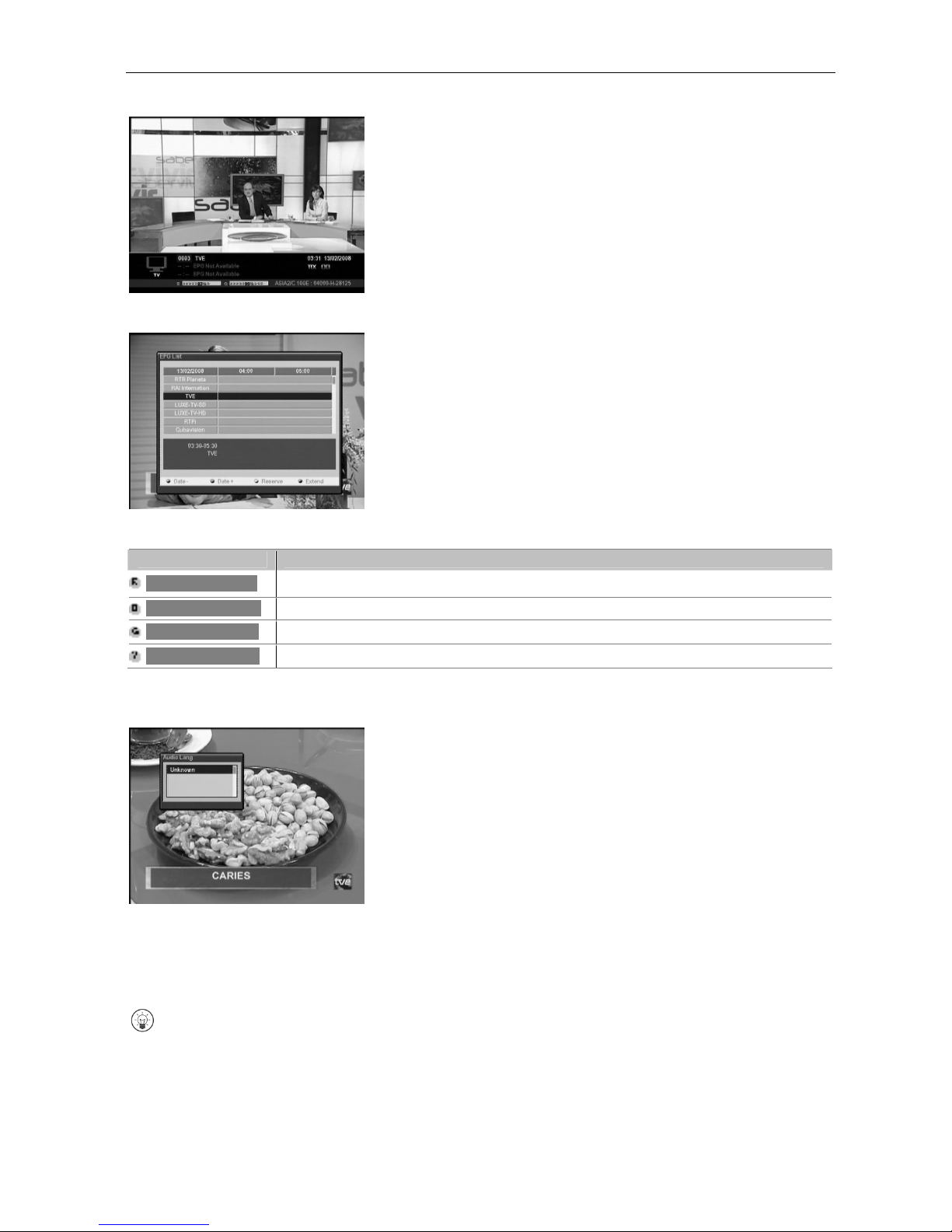
TV/Radio List in Live Mode
If you press OK on remote controller at Live mode, the screen will display as follows.
You can preview the channel.
Channel List
You can change channel information in the "Channel List" of
Main Menu.
And else In normal li
ve mode if press OK button, Channel
manager will be displayed.
Channel Filter
This will print the channel list by selected conditions, which are
FTA/CAS, Satellite and Alphabet.
Sub Menu Function / Tips
FTA/CAS
Free+CA / Free Only / CA Only / SECA / Viaccess / Irdeto / Conax / Cryptoworks / Betacrypt
Negravision / Videoguard / SkyCrypt / DreamCrypt / Keyfly / XCrypt / PowerView / ETC CA
Satellite Satellite available
Alphabet All, A~Z
Sort Order None / ABC / TP / CAS
Page 32
5. Software Operations
33
Information
Press the INFO button once to display short and extended
information. If you press the button again before the banner
disappears, a new banner will be displayed showing the details of
the current channel.
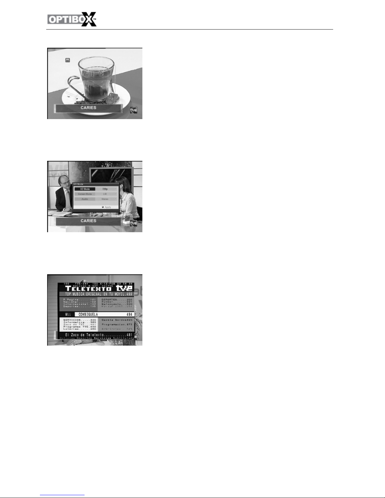
EPG
EPG shows the event information on
the current TP channel by
time Zone. EPG is divided into Daily mode. The event is
displayed only for the channel that have EPG information. If you
press EPG, the daily mode is displayed as a default.
Buttons Function / Tips
Date-
Scroll to yesterday.
Date+
Scroll to next day.
Reserv
Reserves a program on specific channel and time.
Extend
View additional information of channel.
Audio Language availables list
Shows the list of the audio language available in
the current
channel. (The selected audio language information is saved and
applied when you watch the channel.)
You can move in the channel list more fast with the Page UP/DOWN (P+/P-) button.
Page 33
34
PAUSE
Pause the video/audio output of receiver, To
clear pause press
PAUSE button again.
A/V Mode
Sets the current channel audio to stereo, left-mono, right-mono.
Audio : Set up Audio Output.
Screen Mode : Set up Screen Mode.
Apply
Teletext
Shows the list of subtitle languages the current channel supports.
Press TTX Button. You can watch the Teletext contents if it is
available.
Page 34
Appendix
35
A. Trouble Shooting
There may be various reasons for the abnormal operation of the receiver.
Check the receiver according to the procedures shown below.
If the receiver does not work properly after checking it, please contact the dealer.
Don't open the receiver cover. It may cause a dangerous situation.
Symptom Cause Remedy
The display on front
panel doesn't light up
The power cord is not
plugged in.
Check that the power cord is plugged in to
the wall outlet.
No picture or sound
Wrong connection of the
Audio/Video output of the
receiver to TV.
Audio muting.
TV power off.
Connect the Audio/Video output of the
receiver to TV correctly.
Press the MUTE button.
Turn TV on.
No picture
The receiver can't receive the
signal.
Incorrect values of some tuner
parameters.
Wrong direction of the dish
Check the antenna cable, replace the cable, or
connect the cable to the receiver tightly.
Set the values of tuner parameters correctly in
installation menu.
Check the signal strength with a spectrum
analyzer and adjust your dish correctly.
Remote controller
does not working
The batteries of the remote
controller are not inserted or
exhausted
Check whether the batteries are inserted
correctly in your remote controller
Check the batteries, an if exhausted replace
the batteries of the remote controller
B. Specifications
1. Conditional Access Interface (CI Model Only)
PCMCIA
2 Slot(type I or type II)
DVB Common Interface Standard
(Viaccess, Nagra Vision, Conax, Cryptoworks, ASTON)
2. Conax Embedded
SMART CARD
1 Slot
ISO 7816 Compatibility
Page 35
36
3. Tuner & Demodulation
Transmission Standard DVB-S, DVB-S2
Network
Interface
Module
LG TDQR-C003F
- ZIP PLL IC : Conexant CX24118A
- Demodulation IC (8PSK, QPSK) : Conexant CX24116
RF-in Connector Type IEC 60169-24, Female, 75 nominal
Loop Through Output IEC 60169-24, Female,75 nominal
Input Frequency Range 950MHz to 2150MHz
Input Signal Level -65dBm ~ -25dBm
Modulation Modes QPSK, 8PSK
FEC Modes
DVB-S: Auto, 1/2, 2/3, 3/4, 5/6, 7/8
DVB-S2: Auto, 1/2, 3/5, 2/3, 3/4, 4/5, 5/6, 8/9, 9/10 (QPSK)
Auto, 3/5, 2/3, 3/4, 5/6, 8/9, 9/10 (8PSK)
LNB Power Vertical:+13V, Horizontal:+18V, Max 500mA
22kHz Tone 22±4kHz / Amplitude 0.65±0.25Vpp
DiSEqC Version 1.0, 1.2 Compatible
4. MPEG Transport Stream & A/V Decoding
Transport Stream MPEG-2 ISO/IEC 13818 Transport Stream Specification
Profile Level
MPEG-4 part10 (H.264) Level 4
MPEG-2 MP@ML, MP@HL
Input Rate Max. 15MB/s
Aspect Ratio 4:3, 16:9, Letter Box
Frame Rate 25Hz for PAL
Video Resolution 1080i, 720p, 576p, 576i PAL
Audio Decoding
MPEG-1 Layer I & II
Dolby Digital down mixing
Audio Mode Single channel / Dual channel / Joint stereo / Stereo
Audio Sampling Rate 32, 44.1, 48KHz
Page 36
Appendix
37
5. A/V In/Out & Connectivity
HDMI Output: Digital Video & Audio
TV SCART Output: CVBS, Audio L/R with Volume control
VCR SCART
Output: CVBS, Audio L/R
Input: RGB, CVBS, Audio L/R
RCA
Output: CVBS, Audio L/R with Volume Control
Component video (Y, Pb, Pr)
SPDIF Output : Digital Audio (Optical)
Smart card One
CI Two
USB USB 2.0 HOST
Connector: USB A TYPE
Current Consumption: Max. 500mA
RS-232 RS-232 (Bit Rate: 115200baud, Connector: 9-pin D-sub Male type)
Front Keys & Display 10-Keys, 14 digit VFD
6. Power Supply
Input Voltage AC 90~240V, 50/60Hz
Type SMPS
Power Consumption Max 40W
Protection Separate Internal Fuse
7. Physical Specification
Size (WxHxD) 340mm x 60mm x 245mm Excluding the foot. Foot height is 6mm.
Weight 2 Kg
8. Environmental Condition
Operating Temperature 0~40◀
Storage Temperature -10◀~+50◀
Operating Humidity Range 10~85% RH, Non-condensing
Storage Humidity Range 5~90% RH, Non-condensing
Page 37

38
C. Glossary of Terms
C band
3.7 ~ 4.2 GHz Frequency.
Ku band
11 ~ 18GHz Frequency.
DiSEqC
Digital Satellite Equipment Control.
LNB (Low-Noise Block converter)
The LNB is an electronic unit mounted on the satellite dish. It receives the signals reflected by
the dish and converts them to signals that can be used by Satellite receiver.
PID
Package Identifier.
PIN Code
Personal Identification Number. Afour-digit code that is used for locking/unlocking. e.g.
with the parental control feature.
Polarization
Polarization allows several program to be fitted into the same frequency band. The signals
from a satellite are transmitted either with linear(vertical or horizontal) polarization or
circular(right or left) polarization.
RS232
Serial data port.
 Loading...