

Optibike M, R Owner's Manual
OWNER’S MANUAL
V4.0
OPTIBIKE
High Performance Electric Bikes
Opti-Bike, LLC.
U.S. PATENTS #6,296,072 #6,629,574


1
Contact Optibike
e-mail:
Service@Optibike.com
phone: 303.443.0932
You can also find the Opticare
Service portal on Optibike.com
About the Manual
This is the owner’s manual for your Optibike. Please read
the entire manual carefully before riding your Optibike in
order to ensure maximum safety and performance.
Opti-Bike, LLC. assumes no liability for any injury resulting
from failure to read and comply with the information
within this manual. The information and instructions
within this manual are meant to be used as guidelines for
safe operation. It is important to know and follow all the
rules and laws pertaining to safety and transportation in
your area.
Herein, Opti-Bike, LLC. will be referred to as Optibike.
For any immediate concerns, please do not hesitate to
contact Optibike service personnel.

2

3
TABLE OF CONTENTS
IMPORTANT SYMBOLS AND TERMS.......................................4
1. INITIAL ASSEMBLY.............................................................7
1.1 INITIAL BIKE INSPECTION..........................................................7
1.2 ROTATING STEM AND HANDLEBARS...........................................8
1.3 ATTACHING PEDALS..............................................................10
1.4 ATTACHING SEAT POST .........................................................11
1.5 ATTACHING FRONT WHEEL....................................................12
1.6 ATTACHING REAR FENDER .....................................................15
2. BEFORE YOU RIDE ...........................................................16
2.1 FITTING YOUR OPTIBIKE ........................................................16
2.2 SAFETY CHECKLIST................................................................18
3. OPERATING YOUR OPTIBIKE............................................20
3.1 RIDING SAFELY ....................................................................20
3.2 OPERATING CONDITIONS.......................................................21
3.3 PROPER OPTI-BIKING TECHNIQUE............................................22
3.4 POWERING YOUR OPTIBIKE....................................................24
3.5 OPTIBIKE BATTERY AND CHARGING..........................................25
3.6 OPTIBIKE OPERATING MODES ................................................28
4. MAINTENANCE................................................................31
4.1 TORQUE SPECIFICATIONS:......................................................31
4.1 SCHEDULED MAINTENANCE ...................................................32
4.2 STORAGE............................................................................33
4.3 SECURITY............................................................................34
5. TROUBLESHOOTING........................................................35
6. BICYCLE WARRANTY........................................................38

4
IMPORTANT SYMBOLS AND TERMS
This manual provides many important instructions, as well as some
specific operating precautions. The following symbols will help you
navigate the manual:
Symbol Meaning
Important: This symbol denotes a crucial detail to the
specified task. Take extra time to read this point and
follow it closely.
Warning/Caution: This symbol denotes a potentially
hazardous situation, which could lead to personal
injury or bike malfunction. Be sure to heed and follow
these instructions.
Note: This symbol denotes additional useful
information or text pertaining to the page in which it is
contained.
Tools: Look for this symbol to find a list of tools
required for a specific task.
!
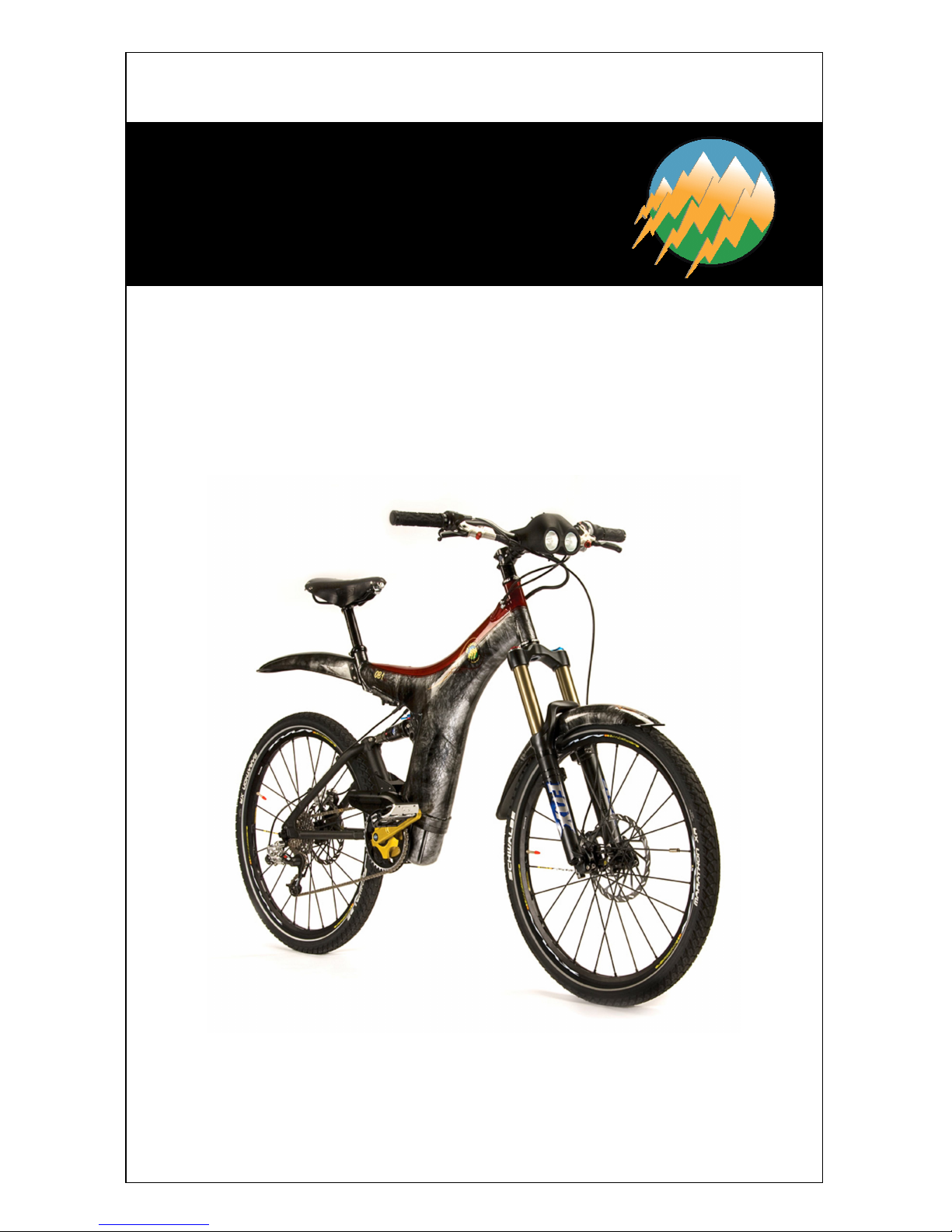
COMPONENTS
5
KEY
1.
Motorized Bottom
Bracket (MBB)
2.
Monocoque Aluminum
Frame
3.
Front Fork Suspension
4.
Front Fender 5. Front Wheel 6. Stem 7. Headset 8. Bicycle Computer 9.
Rear Shock Suspension
10.
Rear Fender
11.
Rear Wheel
12.
Derailleur
13.
Triangular Swingarm
14.
Crank Arm
15.
Pedal
16.
Headlight Body and
Control Switches
17.
Handlebars
18.
Seat
19.
Seat Post
20.
Disc Brake
OPTIBIKE COMPONENTS
1
2 3 4 5 6 7 8 9 10 11 12 13 14 15 16 17 18 19 20
COMPONENTS
6
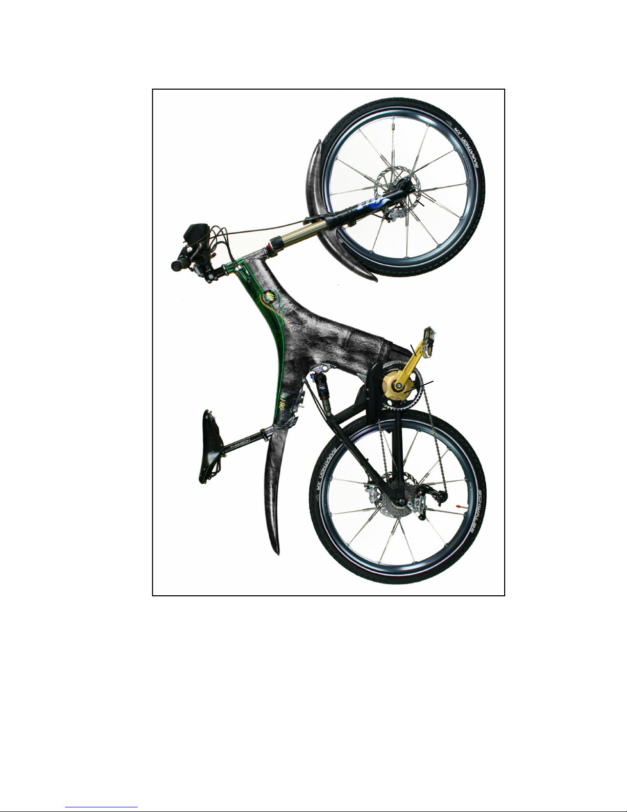
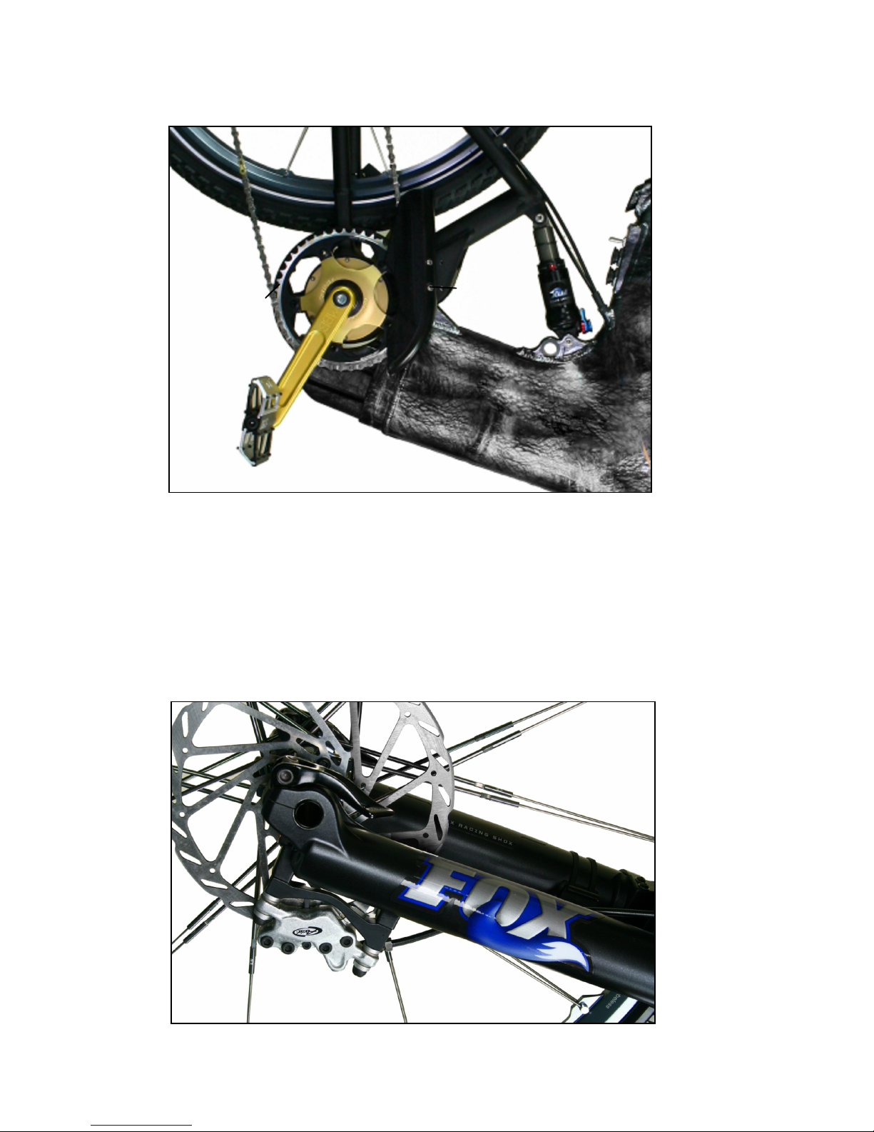
OPTIBIKE COMPONENTS
KEY
21. Brake Rotor
22. Brake Calipers
23. Front Brake Cable
24. Front Fork Suspension 25. Chain
26. Chain-ring
27. Chain Guard
28. Charge Port, External
Battery Port, and Main
Power Switch
29. Lock Port
30. Rear Shift and Brake
Cables
21 22 25 26 27 28 29 30 23 24

INITIAL ASSEMBLY
7
Contact Optibike
e-mail:
Service@Optibike.com
phone: 303.443.0932
You can also find the Opticare
Service portal on Optibike.com
1. INITIAL ASSEMBLY
After unpacking your Optibike according to the instructions
packaged with your bike, you must complete the initial assembly
process as illustrated in the following pages.
If, at any time, you feel the initial assembly is beyond
your experience level or you are uncomfortable with
assembling your Optibike, you should take the Optibike
to a local bicycle shop. A trained bicycle mechanic will be
able to complete the initial assembly process. This
service is not included with the purchase of your
Optibike.
1.1 INITIAL BIKE INSPECTION
Visually inspect your Optibike for
signs of damage. The most obvious
forms of damage will be scratches
or dents to the frame or other
components. If you find damage,
contact Optibike service personnel
immediately and DO NOT proceed
with assembly.
For increased safety and ease, it is recommended that two people
perform initial assembly.
!
INITIAL ASSEMBLY
8
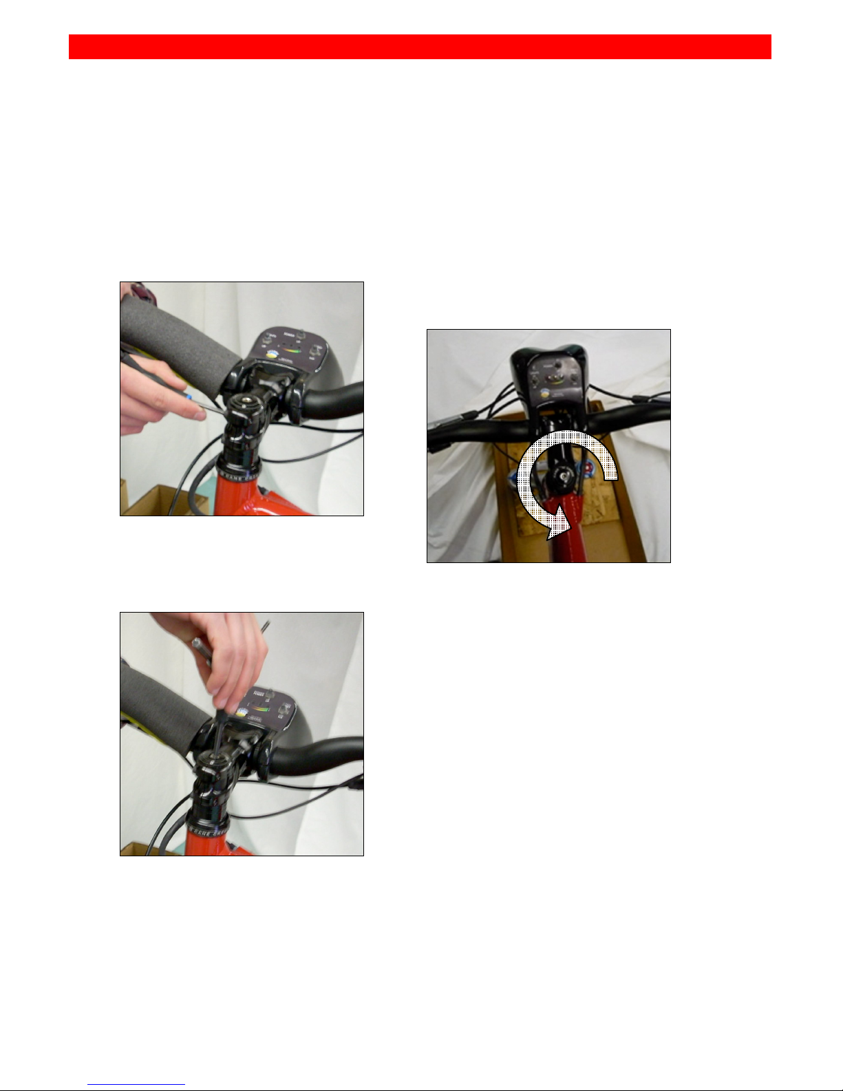
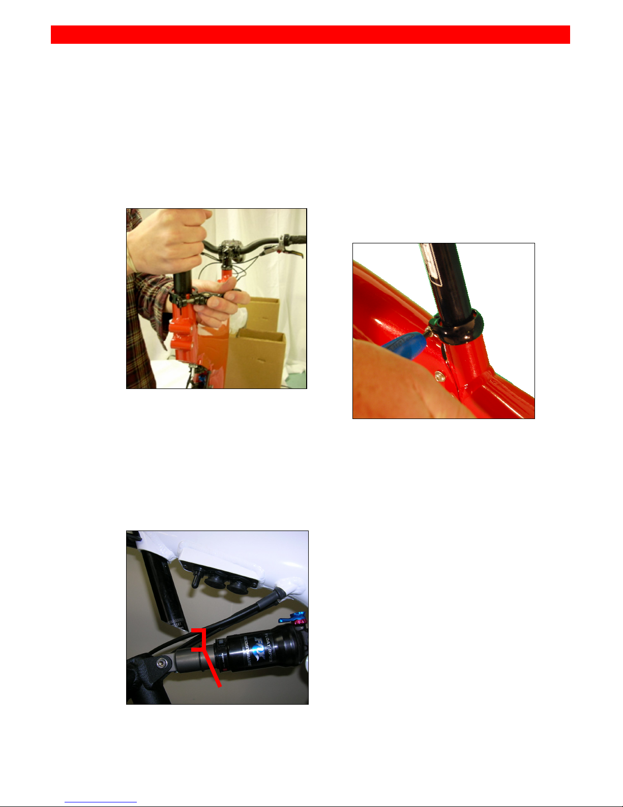
1.2 ROTATING STEM AND HANDLEBARS
Tools: bicycle multi-tool and/or torque wrench.
STEP 1:
Loosen the bolts on the side
of the handlebar stem.
STEP 2:
Loosen bolt on top of stem.
STEP 3:
Rotate stem to proper
position: handlebars should
be parallel to the top of the
front fork.
STEP 4:
Tighten bolt lightly on top of
the stem (see step 2) until
headset can move freely
without excessive play.
STEP 5:
Tighten bolts on the side of
the stem (see step 1). Torque
setting: 35-55 in-lbs; this value
can be found on most bike
stems.
Rotate headlight body
downward so that the
headlights are aimed forward
with a slight downward angle.

INITIAL ASSEMBLY
9
STEP 6:
Loosen four bolts on front of
handlebar stem. Do not
remove these bolts.
STEP 7:
Rotate handlebars within
stem to a comfortable riding
position.
STEP 8:
Tighten four bolts on the front
of the stem. Using a crisscross pattern, rotate each bolt
a few turns at a time until all
are tightened to 35 in-lbs.
Rotate headlight body back to
proper position.
INITIAL ASSEMBLY
10
! !
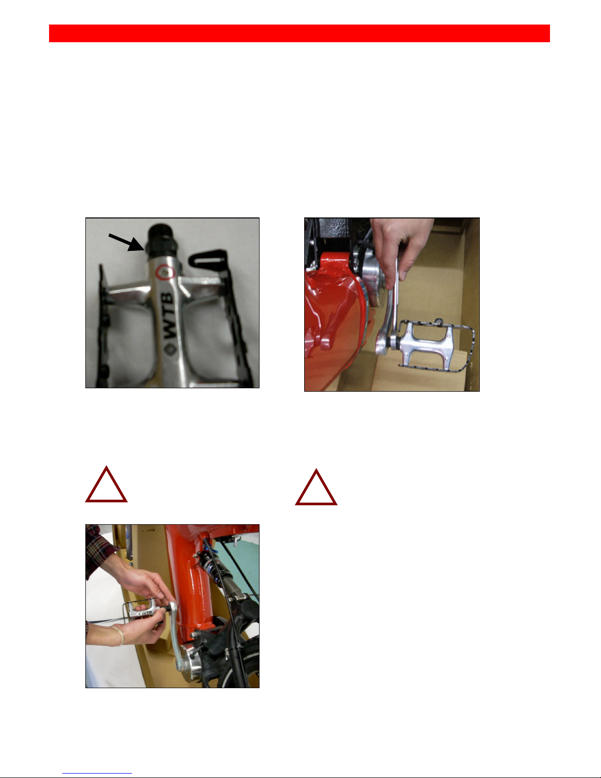
1.3 ATTACHING PEDALS
Tools: 15mm wrench, bicycle multi-tool and/or torque wrench.
STEP 1:
Determine the left pedal; it is
engraved with an L on the
axle.
STEP 2:
Screw left pedal onto left
crank-arm by hand.
Axle is reversethreaded: tighten
counterclockwise.
STEP 3:
Tighten pedal using 15mm
wrench.
Torque setting: 307 in-lbs.
STEP 4:
Repeat steps 1-3 with the right
pedal. The right pedal has
conventional threads:
tighten the right
pedal clockwise.
L
INITIAL ASSEMBLY
11
1.4 ATTACHING SEAT POST
Tools: Ruler, bicycle multi-tool and/or torque wrench.
STEP 1:
Insert seat post into bike
frame.
STEP 2:
Adjust seat to appropriate
height. The bottom of the seat
post should be greater than
0.6 inches (1.5cm) above the
rear shock.
STEP 3:
Firmly tighten the seat clamp
bolt. Minimal torque is
required to prevent seat post
from slipping.
>> 00..66 iinn
 Loading...