

Optibelt ZRP, ZRM, ZRL, ZRL-M, ZRL-V Technical Manual

TECHNICAL MANUAL
OPTIBELT POLYURETHANE
TIMING BELT DRIVES
optibelt
ZRM: AT5 und AT10
optiflex:
Sortiment
Inklusive:

1
Technical Manual
for
Polyurethane Timing Belt Drives
Optibelt ZRM/ZRP/ZRL timing belts are made from
polyurethane and are especially suitable for use in
difficult environmental conditions
Endless Optibelt ZRM/ZRP timing belts, with corresponding Optibelt ZRS pulleys, provide non-slip,
synchronous transmission of power up to several
hundred kilowatts.
Where the requirement is for precise positioning in
linear drives and smoothly operating conveyor
systems, the open-ended and the joined endless
Optibelt ZRL timing belts provide the answer.
All essential information and the methods for calculating drives using Optibelt polyurethane timing belts are
contained in this manual. Should you have any further
questions, the free service provided by our application
engineers is readily available.

2
Produktionsstätten und Vertriebsorganisation der Arntz Optibelt Gruppe
Manufacturing and Distribution Organisation of the Arntz Optibelt Group
Produktionsstätten Factories
Arntz Optibelt GmbH
Postfach 10 01 32 · D-37669 Höxter/Germany
Corveyer Allee 15 · D-37671 Höxter/Germany
Tel. +49 (0) 52 71-6 21
Fax +49 (0) 52 71-97 62 00
A & M Belting Company Ltd.
Ballyraine Industrial Estate
Letterkenny Co. Donegal
Ireland
Tel. +353 (0) 74 91-2 50 66
Fax +353 (0) 74 91-2 50 61
a+m@optibelt.com
Optibelt Produktions GmbH & Co. KG
Carl-Vollrath-Straße 4
D-07422 Bad Blankenburg
Tel. +49 (0) 3 67 41-48 30
Fax +49 (0) 3 67 41-4 21 01
Arntz Belting Company Ltd.
Pennyburn Pass
Londonderry BT48 0AE
Northern Ireland
Tel. +44-28 71-26 12 21
Fax +44-28 71-26 33 86
abc@optibelt.com
Transac S.A.
54, Rue de la Gare
F-68520 Burnhaupt-le-Haut/France
Tél. +33-3-89 62 75 20
Fax +33-3-89 62 75 29
Vertriebsorganisation Deutschland Distribution Organisation Germany
Optibelt GmbH
Corveyer Allee 15
37671 Höxter
Tel. +49 (0) 52 71-6 21
Fax +49 (0) 52 71-97 62 00
info@optibelt.com
www.optibelt.com
Optibelt GmbH
Verkaufsbüro Nord
North Sales District
Corveyer Allee 15
D-37671 Höxter
Tel. +49 (0) 52 71-6 23 03
Fax +49 (0) 52 71-97 62 00
Optibelt GmbH
Verkaufsbüro Süd
South Sales District
Pfauhauser Straße 43
D-73240 Wendlingen
Tel. +49 (0) 70 24- 71 00
Fax +49 (0) 70 24-5 27 92
Vertriebsorganisation Europa Distribution Organisation Europe
Finnland Finland
Optibelt Finland Oy
PL 58
Lampputie 4
FIN-00751 Helsinki
Puh. +358-9-3 46 14 00
Faksi +358-9-3 46 15 00
optibelt@co.inet.fi
Großbritannien
United Kingdom
Optibelt (UK) Ltd.
5 Bishops Court
Winwick Quay
GB-Warrington WA2 8QY
Cheshire
Tel. +44-19 25-41 33 11
Fax +44-19 25-5737 51
optibelt@optibeltuk.co.uk
Frankreich France
Optibelt France S.A.S
54, Rue de la Gare
B.P. N° 13
F-68520 Burnhaupt-le-Haut
Tél. +33-3-89 62 75 10
Fax +33-3-89 62 75 19
optibelt-france@optibelt.fr
Polen Poland
Optibelt Polska Sp. z o.o.
ul. Budowlanych 11
PL-41-303 Da˛browa Górnicza
Tel. +48-32-260 1175/76
Faks+48-32-260 4208
biuro@optibelt.net.pl
Schweden Sweden
Optibelt Skandinaviska AB
Stadiongatan 60
S-21762 Malmö
Tel. +46-40-59 21 20
Direct +46-40-59 21 27
Fax +46-40-49 90 10
optibelt@optibelt.se
Niederlande Netherlands
Optibelt Nederland B.V.
Postbus 39
NL-2140 AA Vijfhuizen
Schipholweg 955
NL-2143 CE Boesingheliede
Tel. +31-23-5 55 16 51
Fax +31-23-5 55 19 26
t-online@optibelt.nl
Schweiz Switzerland
Optibelt AG
Bodenackerstrasse 70
CH-4657 Dulliken
Tel. +41-62-285 50 00
Fax +41-62-285 50 01
vertrieb@optibelt.ch
Ost-Europa
Eastern Europe GUS
Optibelt Russland
Varshavskoje Shosse,
125D, Korpus 1
113587 Moskau
Tel./Fax +7 09 59 95 05 41
Mobile +7 90 37 74 35 34
optibeltrus@ccs.ru
Dänemark Denmark
Optibelt Danmark A/S
International House
Center Boulevard
DK-2300 København S
Tlf. +45-32-47 32 34
Fax +46-40-49 90 10
optibelt@optibelt.dk
Belgien Belgium
Optibelt GmbH
Filiaal België
Cornelis Schutstraat 28
B-2100 Deurne
Tél. +32-3-3 25 22 75
Fax +32-3-3 26 09 55
optibelt@skynet.be
Spanien Spain
Optibelt España, S.A.
Apartado 1141
Rois de Corella, 12
E-08205 Sabadell
Tel. +34-93-7 20 79 60
Fax +34-93-7 11 64 90
administracion@optibelt.net
Südost-Europa
South Eastern Europe
Optibelt GmbH
Südost-Europa · Office Wien
Carlbergergasse 38
A-1230 Wien
Tel. +43-1-8 65 31 00 19
Fax +43-1-8 65 31 00 27
office@optibelt.at
Österreich Austria
Optibelt Österreich GmbH
Carlbergergasse 38
A-1230 Wien
Tel. +43-1- 8 65 43 97
Fax +43-1- 8 65 43 96
office@optibelt.at
Italien Italy
Optibelt AG
Via Dandolo, 1
I-20025 Legnano (Mi)
Tel. +39-0331-48 10 20
Fax +39-0331-48 10 75
optibeltitalia@libero.it
Vertriebsorganisation Nord- u. Südamerika Distribution Organisation North & South America
USA USA
Optibelt Corporation
1120 W. National Avenue
Addison, Illinois 60 101/USA
Tel. +1-630-628-84 00
Fax +1-630-628-61 75
optibelt@msn.com
Kanada Canada
Optibelt (Canada) Inc.
351 Steelcase Road West, Unit 8 & 9
L3R 4H9 Markham, Ontario/Canada
Tel. +1-905-477-8114
Fax +1-905-477-0857
info@optibelt.ca
Brasilien Brasil
Optibelt do Brasil Ltda.
Rua Henrique Monteiro Nr. 90
10 Andar-Pinheiros
CEP 05423-020 São Paulo-SP/Brasil
optibeltdobrasil@optibelt.com
Vertriebsorganisation Asien Distribution Organisation Asia
Singapur Singapore
Optibelt Asia Pacific Pte. Ltd.
No. 4 Loyang Way 1, # 01-02/03
Singapore 508708
Tel. +65-6545 4682
Fax +65-6545 4685
sales@optibelt.com.sg
China China
Optibelt Power Transmission (Shanghai) Co., Ltd.
# 55 Miaosan Road, Songjiang District
Shanghai 201612/P.R. China
Tel. +86-21-5768 7465
Fax +86-21-5768 7462
sales@optibelt.com.cn
2

3
Contents
Foreword . . . . . . . . . . . . . . . . . . . . . . . . . . . . . . . . . . . . . . . . . . . . . . . . . . . . . . . . . . . . . 1
Manufacturing and Distribution Organisation of the Arntz Optibelt Group . . . . . . . . . . . . . . . . 2
Contents . . . . . . . . . . . . . . . . . . . . . . . . . . . . . . . . . . . . . . . . . . . . . . . . . . . . . . . . . . . . . 3
1 Product Description
1.1 Construction . . . . . . . . . . . . . . . . . . . . . . . . . . . . . . . . . . . . . . . . . . . . . . . . . . . . . . . 4
1.2 Applications . . . . . . . . . . . . . . . . . . . . . . . . . . . . . . . . . . . . . . . . . . . . . . . . . . . . . . . 6
1.3 Types and sections . . . . . . . . . . . . . . . . . . . . . . . . . . . . . . . . . . . . . . . . . . . . . . . . . . . 8
1.4 Special constructions . . . . . . . . . . . . . . . . . . . . . . . . . . . . . . . . . . . . . . . . . . . . . . . . . 9
2 Basics of Drive Design
2.1 Service factors, additional factors and formulae . . . . . . . . . . . . . . . . . . . . . . . . . . . . . . . 12
2.2 Symbols used in formulae . . . . . . . . . . . . . . . . . . . . . . . . . . . . . . . . . . . . . . . . . . . . . . 14
3 ZRM/ZRP Timing Belts
3.1 ZRM/ZRP resistance to chemicals . . . . . . . . . . . . . . . . . . . . . . . . . . . . . . . . . . . . . . . . 15
3.2 ZRM/ZRP optiflex timing belt range . . . . . . . . . . . . . . . . . . . . . . . . . . . . . . . . . . . . . . . 16
3.3 ZRM/ZRP belt selection graphs . . . . . . . . . . . . . . . . . . . . . . . . . . . . . . . . . . . . . . . . . . 24
3.4 ZRM/ZRP drive design . . . . . . . . . . . . . . . . . . . . . . . . . . . . . . . . . . . . . . . . . . . . . . . . 26
3.5 ZRM/ZRP tensioning . . . . . . . . . . . . . . . . . . . . . . . . . . . . . . . . . . . . . . . . . . . . . . . . . 28
3.6 ZRM/ZRP power rating table . . . . . . . . . . . . . . . . . . . . . . . . . . . . . . . . . . . . . . . . . . . . 29
4 Open-Ended and Joined Endless Optibelt ZRL Timing Belts for Linear Drives
and Conveying
4.1 ZRL timing belt range . . . . . . . . . . . . . . . . . . . . . . . . . . . . . . . . . . . . . . . . . . . . . . . . . 30
4.2 ZRL graph of torque . . . . . . . . . . . . . . . . . . . . . . . . . . . . . . . . . . . . . . . . . . . . . . . . . . 32
4.3 ZRL-M drive design . . . . . . . . . . . . . . . . . . . . . . . . . . . . . . . . . . . . . . . . . . . . . . . . . . . 34
4.4 ZRL-V drive design . . . . . . . . . . . . . . . . . . . . . . . . . . . . . . . . . . . . . . . . . . . . . . . . . . . 37
4.5 ZRL tensioning . . . . . . . . . . . . . . . . . . . . . . . . . . . . . . . . . . . . . . . . . . . . . . . . . . . . . . 40
4.6 ZRL circumferential force and torque table . . . . . . . . . . . . . . . . . . . . . . . . . . . . . . . . . . . 41
4.7 ZRL resistance to chemicals . . . . . . . . . . . . . . . . . . . . . . . . . . . . . . . . . . . . . . . . . . . . . 42
5 Design Hints, Dimensions and Tolerances
5.1 Allowances, length tolerances . . . . . . . . . . . . . . . . . . . . . . . . . . . . . . . . . . . . . . . . . . . 43
5.2 Standard pulleys, flanged pulleys, idlers, clamping plates and minimum numbers of teeth . . 44
5.3 Operating, safety and maintenance hints, installation . . . . . . . . . . . . . . . . . . . . . . . . . . . 46
5.4 Standards, pulley tolerances . . . . . . . . . . . . . . . . . . . . . . . . . . . . . . . . . . . . . . . . . . . . 48
5.5 Length measurement, width tolerances . . . . . . . . . . . . . . . . . . . . . . . . . . . . . . . . . . . . . 50
5.6 Problems, causes, remedies . . . . . . . . . . . . . . . . . . . . . . . . . . . . . . . . . . . . . . . . . . . . . 52
Taper Bushes, Timing Belt Pulleys and Clamping Plates
Taper bushes . . . . . . . . . . . . . . . . . . . . . . . . . . . . . . . . . . . . . . . . . . . . . . . . . . . . . . . 54
Timing belt pulleys . . . . . . . . . . . . . . . . . . . . . . . . . . . . . . . . . . . . . . . . . . . . . . . . . . . 55
Recommended pulleys – special constructions . . . . . . . . . . . . . . . . . . . . . . . . . . . . . . . . 90
Clamping Plates . . . . . . . . . . . . . . . . . . . . . . . . . . . . . . . . . . . . . . . . . . . . . . . . . . . . . 91
ZRM/ZRP Data Sheet and Notes . . . . . . . . . . . . . . . . . . . . . . . . . . . . . . . . . . . . . . . . . . . . 93
ZRL Data Sheet and Notes . . . . . . . . . . . . . . . . . . . . . . . . . . . . . . . . . . . . . . . . . . . . . . . . . 95
4
Introduction
Since the introduction of the first timing belt at the end of the 40’s,
this type of drive element has gained in importance for the
synchronous transmission of torque and power. The non-slip timing
belt has been successfully employed in many standard drives and
has provided economical design solutions in every sector of
mechanical engineering.
The position that the timing belt occupies today is due to the
development of tooth profiles and belt design. The Optibelt ZRM/
ZRP/ZRL single and double-section polyurethane timing belts are a
result of this progress. The properties specific to the polyurethane,
offer the following advantages:
● High resistance to abrasion
● Good to very good resistance to oil, grease and a
number of aggressive chemicals
● Colour fast
● Simple to weld, for attaching cleats and joining
endless to make belts of any length
● High resistance to tooth shear
● Good thermal tolerance (–30
°C to +80 °C)
● Good electrical insulation properties using poly-
urethane with Aramid tension cord
● Ageing resistant
● Ozone and UV resistant
Apart from the higher noise level at high belt speeds when
compared to V-belt drives, the timing belt has all of the advantages
of other drive mechanisms.
● Synchronous speed transmission, high angle and
positional accuracy due to the low-stretch tension
member and to the positive pulley/belt interlock.
● Double section belts permit multi-pulley arrange-
ments and contra-rotating pulleys.
● Belt flexibility allows high drive ratios requiring
minimum space.
● Low belt specific mass enables high belt speeds.
● Low-stretch tension cord means zero maintenance.
● High drive efficiency due to belt flexibility and lack
of slip.
● The low drive tension allows the use of smaller drive
bearings.
● No drive lubricant necessary, thus the drive is envi-
ronmentally friendly.
● Durable belt components ensure longer belt life.
1 Product Description
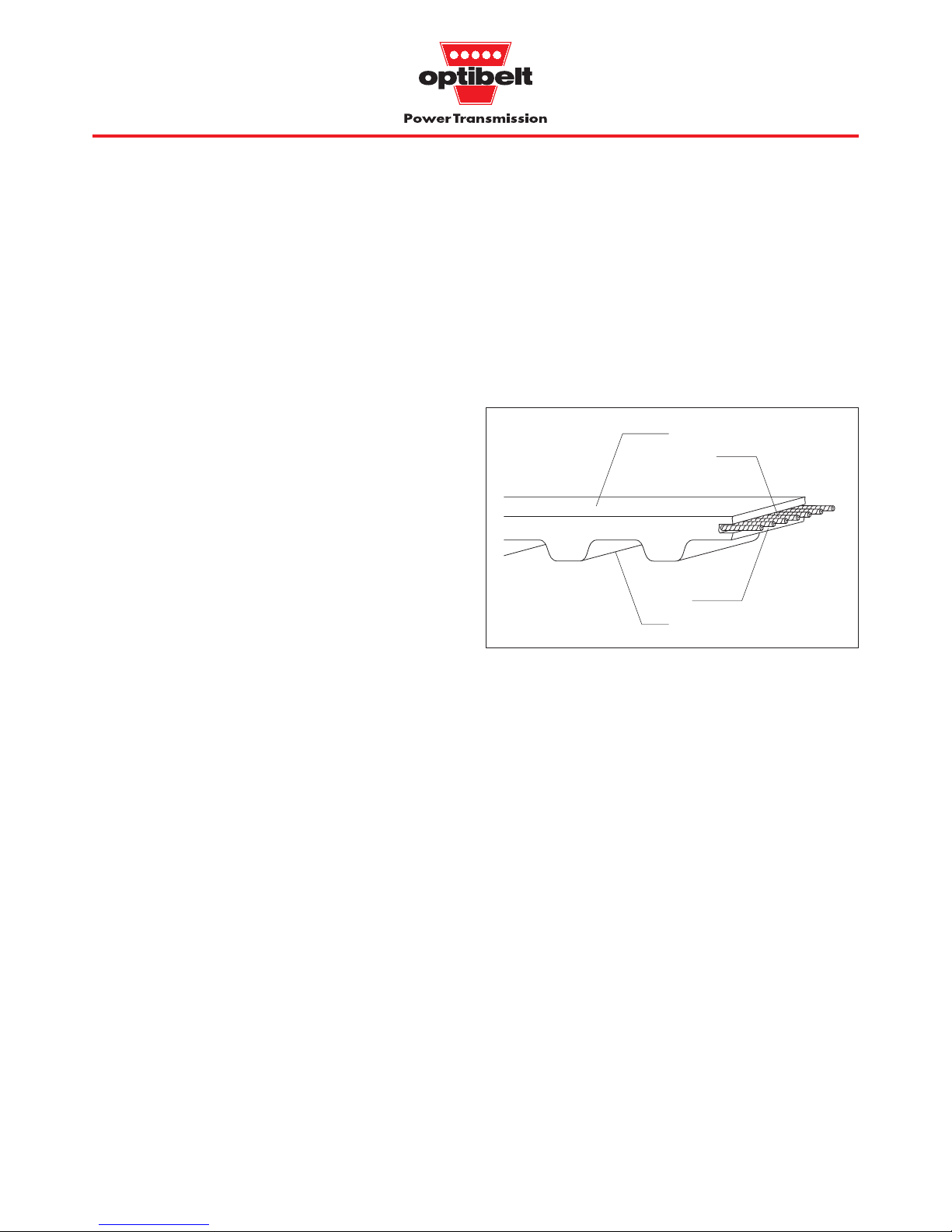
1.1 Construction
In addition to the features of the standard synchronised drive, the
Optibelt ZRM/ZRP/ZRL timing belts offer the additional advantages of polyurethane, as shown above, as a contribution to the
economical solution of design problems.
Top surface
Tension cord
Tooth
Base
Construction: Timing belts
Fig.1.1: Timing belts
a) Top surface
The top surface of the belt is polyurethane. Its function is to hold and
support the tension cord. This abrasion-proof, thin and extremely
flexible layer also protects the tension cord against wear and the
effects of ambient conditions.
b) Tension cord
The tension cord of the endless Optibelt ZRM/ZRP timing belt is
spirally wound steel cord. The teeth, base and top surface form a
unit so that the tension cord is enclosed in polyurethane.
The extremely strong, low stretch tension cord has a very small
cross section.
The open-ended Optibelt ZRL-M belting has parallel steel or
Aramid tension cords. This is also the case with the joined endless
Optibelt ZRL-V timing belt.
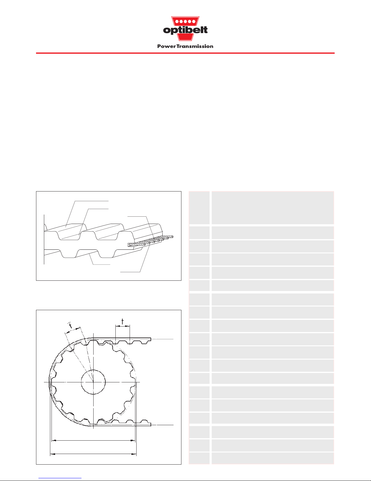
c) Teeth and base
The polyurethane teeth transfer power between the pulley teeth and
the belt tension cord, whilst the polyurethane base cushions the
tension cord against the abrasion from the top of the pulley teeth
(see Fig. 1.3).
The durable, shear resistant belt teeth are so formed and arranged
as to engage with the matching pulley with minimum friction and
maximum precision. When six teeth on the belt type ZRL-V, and
twelve teeth or more on the ZRM, ZRP and ZRL-M belts are in mesh
with the small pulley at any one time, their shear resistance exceeds
the maximum permitted circumferential force of the timing belt.
5
1 Product Description
1.1 Construction
Fig.1.3: Timing belt / pulley relationship
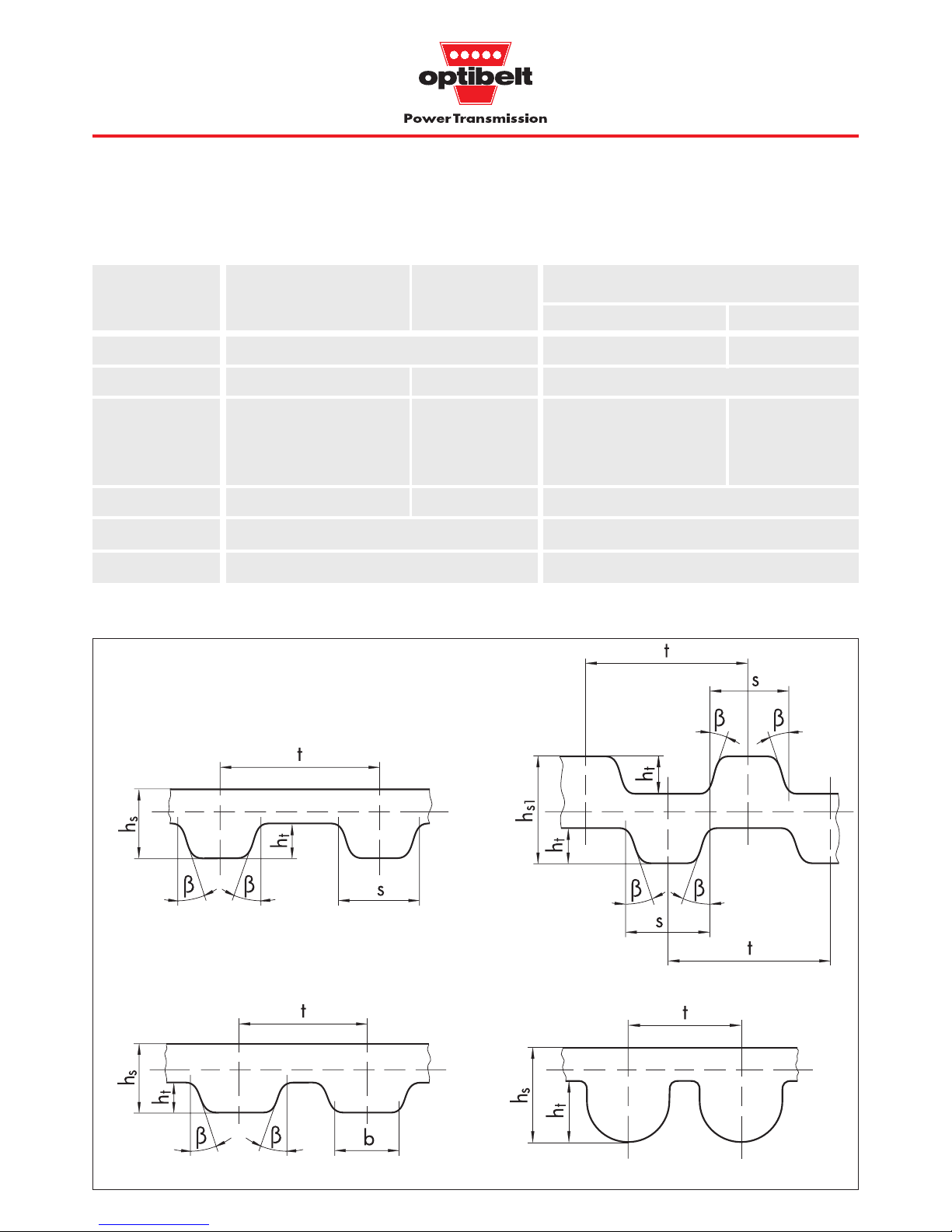
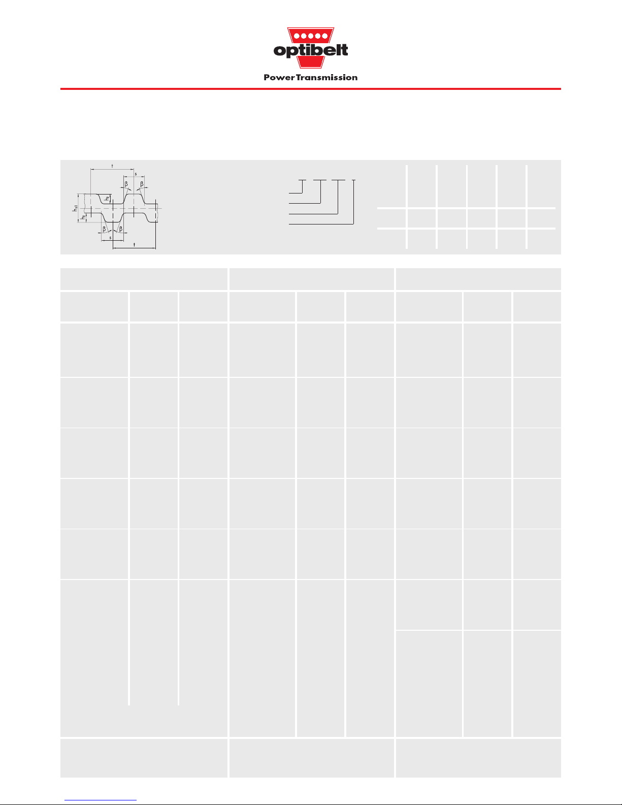
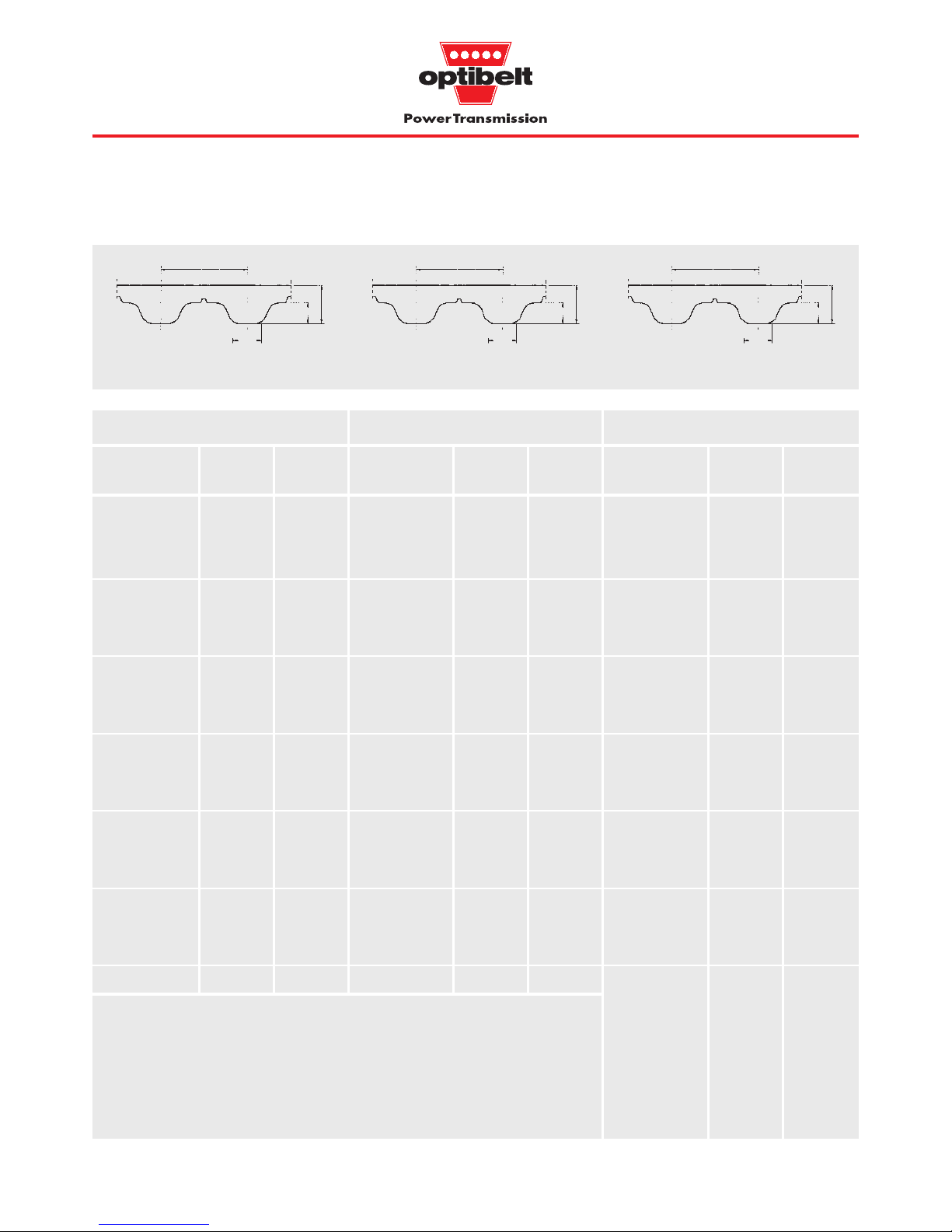
Fig.1.2: Double section timing belt
Section
Overall
belt
thickness
h
s1
(mm)
Tooth
angle
2 β
(°)
Tooth
depth
h
t
(mm)
Tooth
width
at top
b
(mm
)
Tooth
pitch
t
(mm)
Overall
belt
thickness
h
s
(mm
)
Tooth
width
at base
s
(mm)
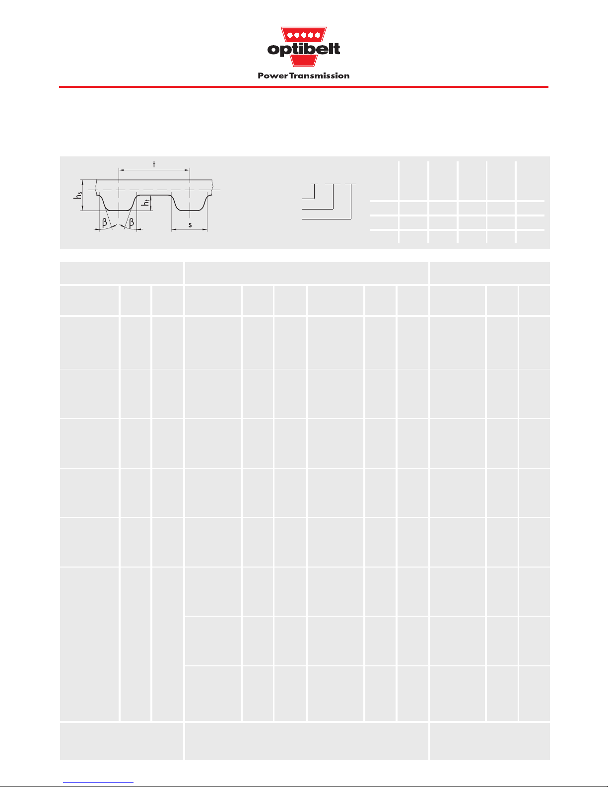
Table 1.1: Section dimensions, sections see Fig. 1.5, page 8,
Standards see Table 5.6, page 48
MXL 2.032 1.14 — 0.51 1.14 — 40
XL 5.080 2.30 — 1.27 2.57 — 50
L 9.525 3.60 — 1.91 4.65 — 40
H 12.700 4.30 — 2.29 6.12 — 40
XH 22.225 11.20 — 6.35 12.57 — 40
T2.5 2.500 1.30 — 0.70 1.50 — 40
T5 5.000 2.20 — 1.20 2.65 — 40
T5D 5.000 — 3.4 1.20 2.65 — 40
T10 10.000 4.50 — 2.50 5.30 — 40
T10D 10.000 — 7.0 2.50 5.30 — 40
T20 20.000 8.00 — 5.00 10.15 — 40
T20D 20.000 — 13.0 5.00 10.15 — 40
AT5 5.000 2.70 — 1.20 — 2.50 50
AT10 10.000 5.00 — 2.50 — 5.00 50
AT20 20.000 9.00 — 5.00 — 10.00 50
5M 5.000 3.60 — 2.10 — — —
8M 8.000 5.60 — 3.38 — — —
14M 14.000 10.00 — 6.10 — — —
The tooth pitch ‘t’ is the distance between two corresponding points
on adjacent teeth on either the belt or the pulley effective diameter.
When the timing belt is laid flat the tooth pitch ‘t’ can be measured
from tooth centre to centre.
When the belt is bent around a pulley the tooth pitch ‘t’ is measured
at the level of the tension cord, also called the effective radius. The
effective diameter ‘d
d
’ thus describes a circle which lies outside the
perimeter of the pulley (d
d
> da).
Construction of the double section timing belt
The construction of the double section timing belt is similar to the
normal timing belt already described. The number and spacing of
the teeth are identical on both sides of the belt, but the two sides
are offset to each other (see Fig. 1.2).
The tension cord and its position relative to the base and teeth are
the same. The maximum permitted power of the double section
timing belt is therefore not doubled but is the same as for the
corresponding normal belt. The power can be transmitted by both
sides of the belt as required.
Base
Tooth
Tooth
Base
Tension cord
d
a
d
w
6
1 Product Description
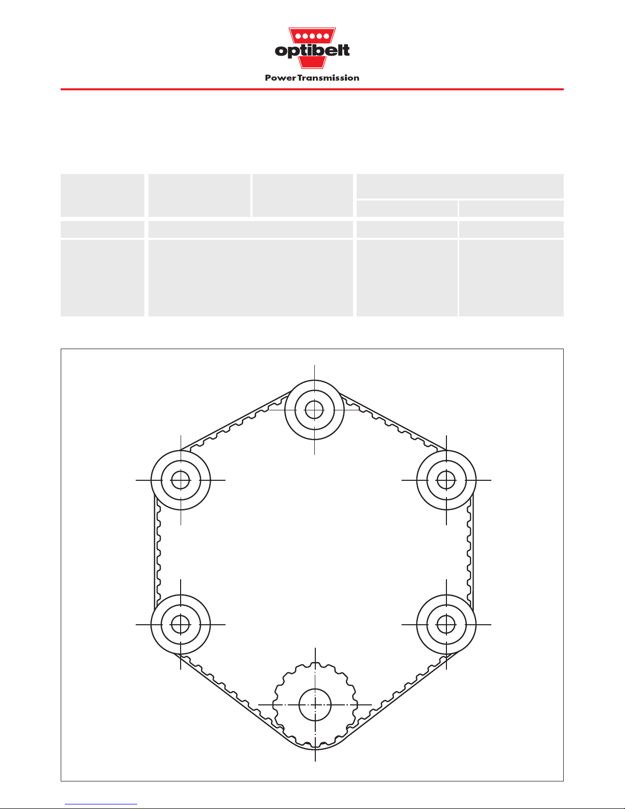
1.2 Applications
Table 1.2: Types and applications
Type ZRM ZRP ZRL
ZRL-M ZRL-V
Applications Synchronous power transmission Linear drives Conveying
Examples: Machine tools Doors and door drives Conveyor systems
Textile machines Washing systems Ram conveyors
Printing presses Reciprocating drives Feeding systems
Packaging machines Mechanical handling Haul-off belts
Domestic appliances equipment Drives with large
Office machines Robots centre distances
Medical equipment Positioning drives
Fig. 1.4.1: Synchronous power transmission
Multi-spindle drives
• •
•
•
• •
•
•
• •
•
•
• •
•
•
• •
•
•
7
1 Product Description
1.2 Applications
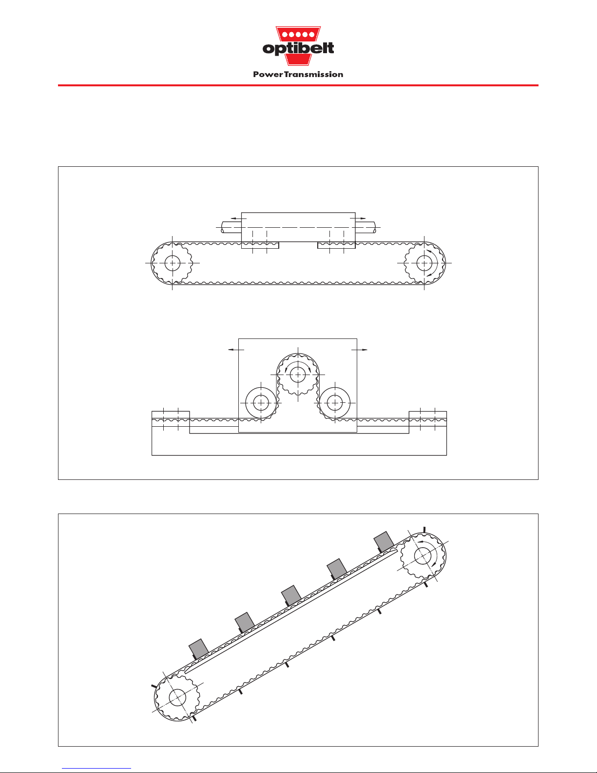
Fig. 1.4.2: Linear drives
Fig. 1.4.3: Conveying
Inclined conveyors with cleats
Trolley drives
Positioning drives
•
•
•
•
•
•
•
•
•
•• •
•
•
•
•
••• •
•
•
•
•
•
•
• • • • • ••
•••
•
•
•
•
•
•
•
•
•••
•
•
•
•••
•
•
•
•
••
••
•
•
•
•
8
1 Product Description
1.3 Types and sections
Type ZRM ZRP ZRL
ZRL-M ZRL-V
Construction manufactured endless open-ended joined endless
metric inch metric and inch
Section T2.5 MXL* T5 AT5 XL T5 AT5 XL
T5 T5D AT5* XL 5M* L L
T10 T10D AT10* L T10 AT10 8M* H T10 AT10 H
T20* T20D* AT20* T20 AT20* 14M* XH T20 XH
5M 8M 14M
Verzahnung ??? single, double (D) single single
Standard tension cord
steel (St), MXL = Aramid (AR) steel (St), Aramid (AR)
Special tension cord Aramid (AR) —
Table 1.3: Types and sections
∗ Non stock (8M and 14M with steel tension cord can be supplied from stock)
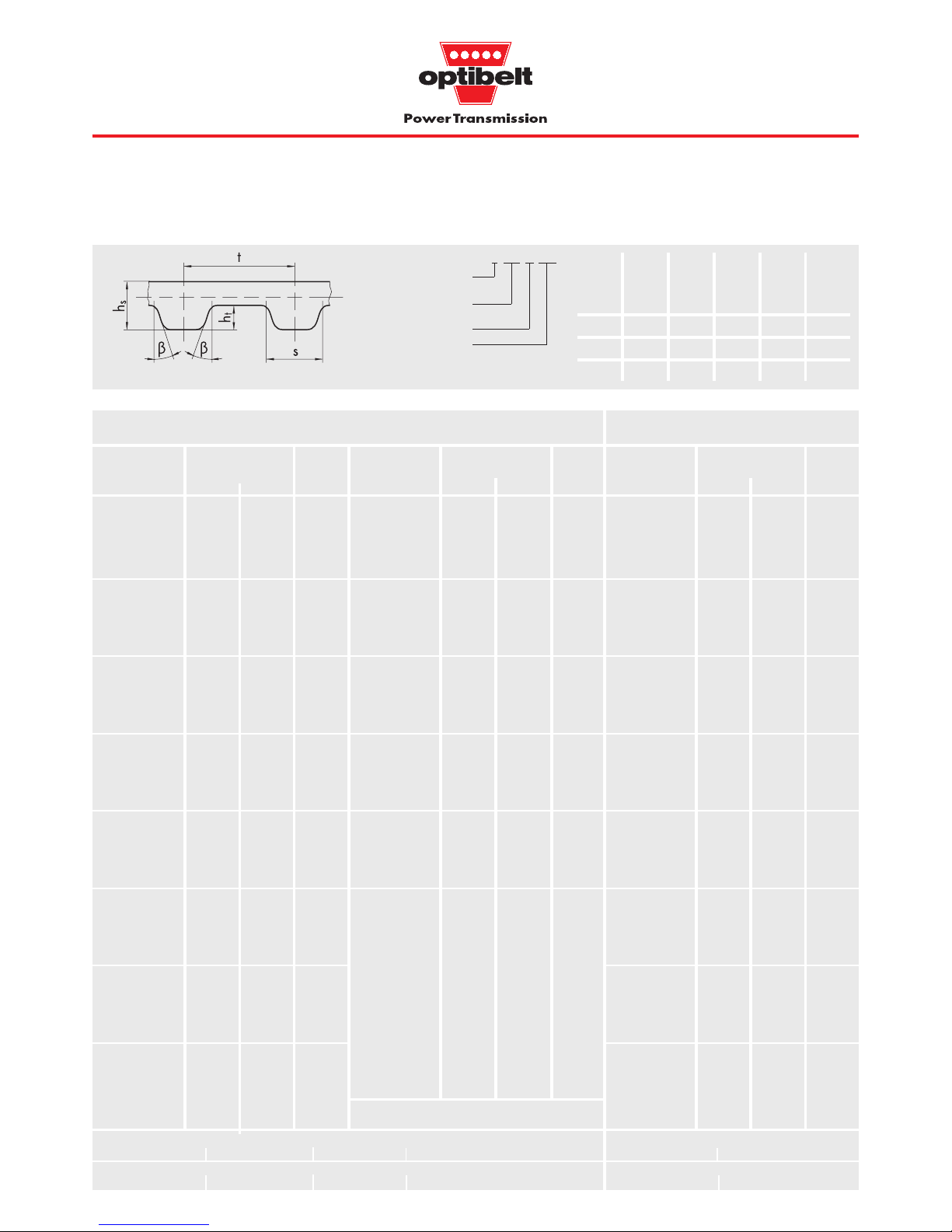
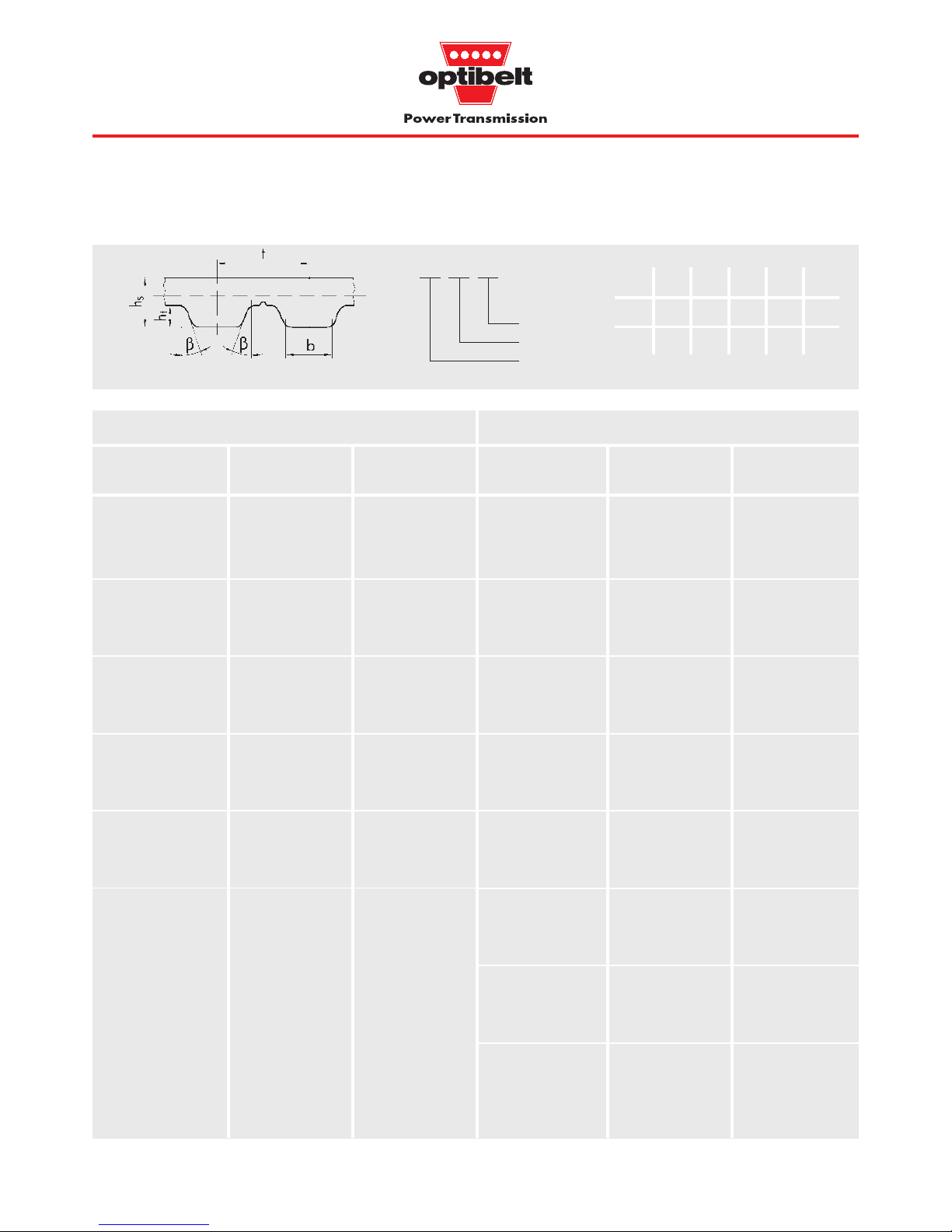
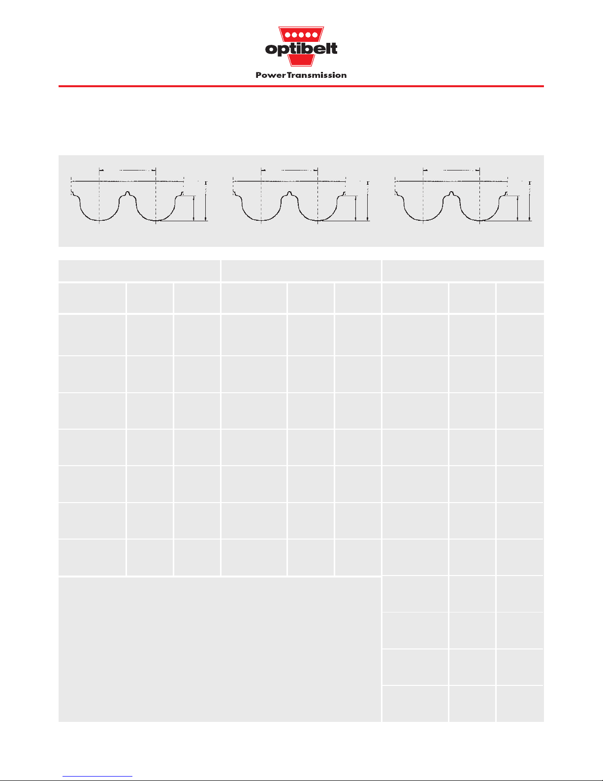
Sections AT5; AT10; AT20 Sections 5M; 8M; 14M
Fig. 1.5: Sections, section dimensions see Table 1.1, page 5
Sections MXL; XL; L; H; XH; T2.5; T5; T10; T20
Sections T5D; T10D; T20D
Measurement/
identification units
•
•
•
•
•••••
•
•
•
•
•
•
••
•• •
•
•
•
•
•
•
•
•
•
•
•••••••
•
•
•
•
•
•
••• •
•
•
•

9
1 Product Description
1.4 Special constructions
Table 1.4: Additional top surfaces
Linatex, Natural 40 – 30 to patterned (to 1.2; 1.6; no furniture industry,
red rubber + 60 1.6 mm thick), 2.4; 3.2; haul-off and
smooth (from 4.8; 6.4; conveying systems
2.4 mm thick), 8.0;
very good coef- 10.0;
ficient of friction, 12.7
abrasion resistant
Supergrip, PVC 40 – 30 to coarse structure, 4.5 conditionally woodworking
blue-green + 80 good coefficient industry,
of friction, inclined transport
abrasion resistant
under certain
conditions
HV 1-film, Poly- 85 – 30 to smooth, 1.0; yes food industry,
HV 2-film, urethane + 80 very good 2.0 glass transport
transparent abrasion
resistance,
superior wear
resistance
Foam PUR 40 – 30 to fine grain, 1.0; 2.0; yes packaging industry
Vulkolan, foam + 80 good coefficient 3.0; 4.0; (lightweight goods),
beige of friction, 5.0; 6.0 transport of
good abrasion sharp-edged objects
resistance,
cut resistant
Solid Poly- 70 – 30 to fine grain, 2.0; 3.0; yes packaging industry
Vulkolan, urethane + 80 good coefficient 5.0; 6.0 (heavy goods),
beige of friction, transport of
good abrasion sharp-edged objects
resistance,
superior wear
resistance
Porol, Cellular 25 – 30 to fine grain, 2.0; 3.0; yes transport of
black rubber + 90 very good coef- 5.0; 8.0; impact-sensitive
ficient of friction, 10,0 goods,
abrasion resistant suction systems
under certain (lightweight materials)
conditions,
cut resistant
PU 06, Poly- 50 – 30 to very fine grain, 2.0; 3.0; yes glass industry,
yellow or grey urethane + 80 high density, 4.0; 5.0; packaging industry,
good coefficient 8.0 transport of
of friction, sharp-edged objects
good abrasion
resistance,
cut resistant
Studs, PVC 65 – 30 to coarse structure, 1.5 yes food industry,
white + 80 good coefficient woodworking industry
of friction,
abrasion resistant
under certain
conditions
Intermediate thicknesses can be made by doubling or grinding the top surface cover.
Top surfaces other than the examples given in Table 1.4 are also available.
noitangiseD
ruolocdnaruolocdna
ruolocdna
ruolocdnaruolocdna
lairetaM
ssendraH
.xorppa.xorppa
.xorppa
.xorppa.xorppa
)AerohS()AerohS(
)AerohS(
)AerohS()AerohS(
erutarepmeT
ecnatsiserecnatsiser
ecnatsiser
ecnatsiserecnatsiser
)C°(.ac)C°(.ac
)C°(.ac
)C°(.ac)C°(.ac
seitreporP
dradnatS
sessenkcihtsessenkciht
sessenkciht
sessenkcihtsessenkciht
)mm()mm(
)mm(
)mm()mm(
dnaliO
foorp-esaergfoorp-esaerg
foorp-esaerg
foorp-esaergfoorp-esaerg
noitacilppalacipyT
10
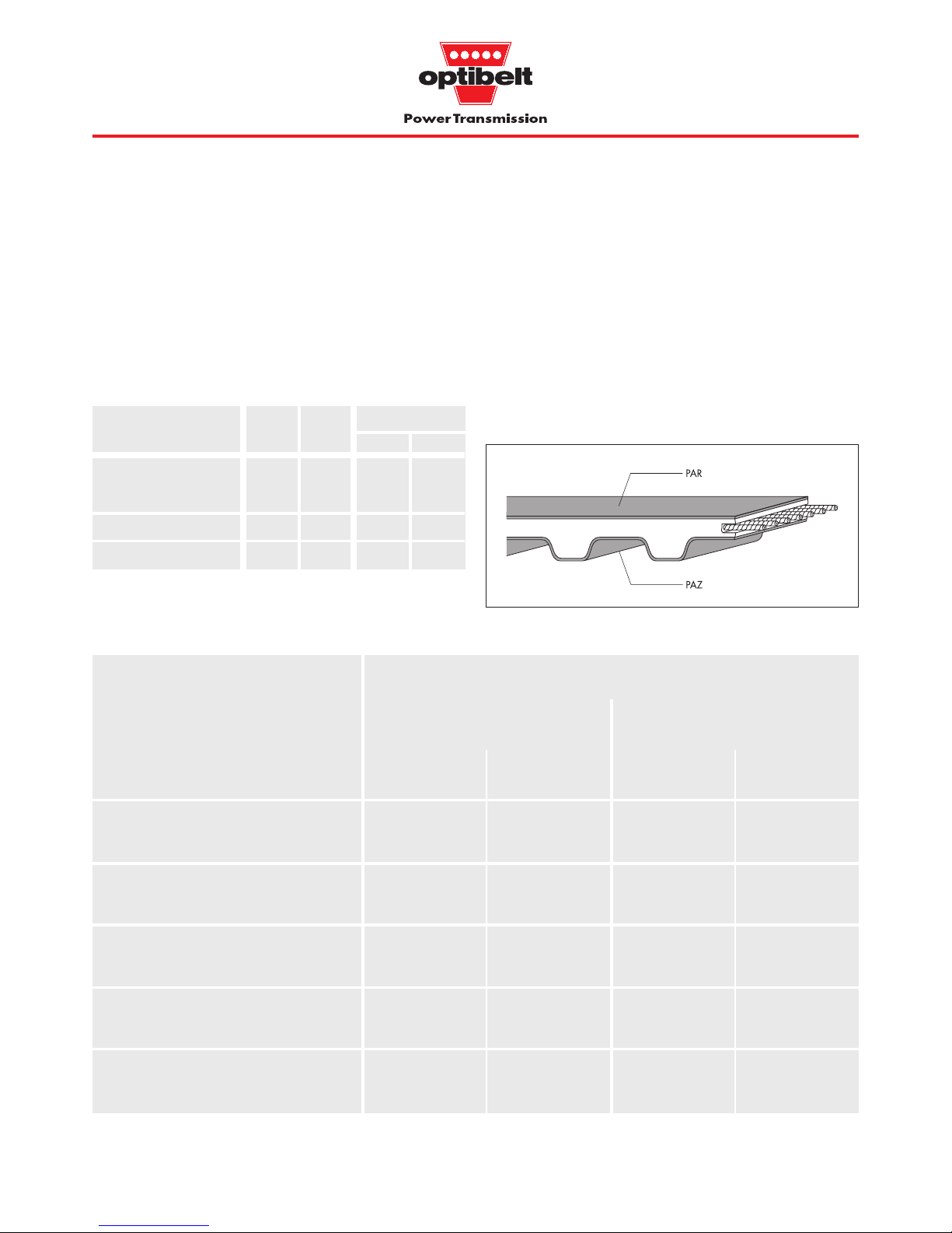
Fabric facing
Optibelt timing belts can be supplied with polyamide fabric on
either the top face or the toothed face of the belt. This fabric offers
less friction resistance than polyurethane and is ideally suited for
facing on belts (PAR) used on ram conveyor applications. Fabric
covering on the toothed face (PAZ) is used to reduce static and
sliding friction on belts which need to be supported on this face by
plastic or metal rails. Support rails are used primarily on belt hauloff and feeder sections where support idlers are widely spaced.
Fig. 1.6: Timing belt with fabric facing on both sides
1 Product Description
1.4 Special constructions
Optibelt timing belts can be adapted to the most varied of
applications in the conveying, control and handling fields, by the
appropriate choice of top surfaces, fabric facings and cleats.
The Optibelt ZRM/ZRP timing belts, intended for use for power
transmission can also be provided with an additional top surface.
Table 1.5: Special constructions
The special constructions shown in Table 1.5 can be combined with
one another.
Special ZRM ZRP ZRL
construction ZRL-M ZRL-V
Fabric facings
– top face (PAR) ●●
– toothed face (PAZ) ●●
Additional top surfaces ●●●●
Conveyor cleats ●●
* polyamide fabric is required where sliding friction is important
Which of the coefficients of friction is used depends upon whether
the conveyed components are static or sliding on the belt. The
coefficients of friction apply for dry conditions and can vary with
belt speed, heat dissipation rate and texture of the surface of the
materials in contact. The upper and lower limits of the coefficients
of sliding friction are based on a belt speed of 0.1 to 1.0 m/sec.
≥ 0.40 ≥ 0.25
≤ 0.70 ≤ 0.45
≥ 0.50 ≥ 0.20
≤ 0.90 ≤ 0.30
≥ 0.30 ≥ 0.20
≤ 0.50 ≤ 0.35
≥ 0.85* ≥ 0.30
≤ 1.00* ≤ 0.50
≥ 0.50 ≥ 0.20
≤ 0.85 ≤ 0.35
µ
0
µµ
0
µ
R
z
= 16 µm
R
z
= 6,3 µm
Table 1.6: Coefficients of friction
slairetamtcatnoC noitcirffostneiciffeoC
enahteruyloP
gnicafcirbafRAP/ZAPtuohtiw
enahteruyloP
gnicafcirbafRAP/ZAPhtiw
noitcirfcitatsnoitcirfgnidilsnoitcirfcitatsnoitcirfgnidils
,leetS
5554
,muinimulA
0553
enelyhteyloP
5252
,ssalG
htooms
0503
,dooW
niargehthtiw
5353.0
11
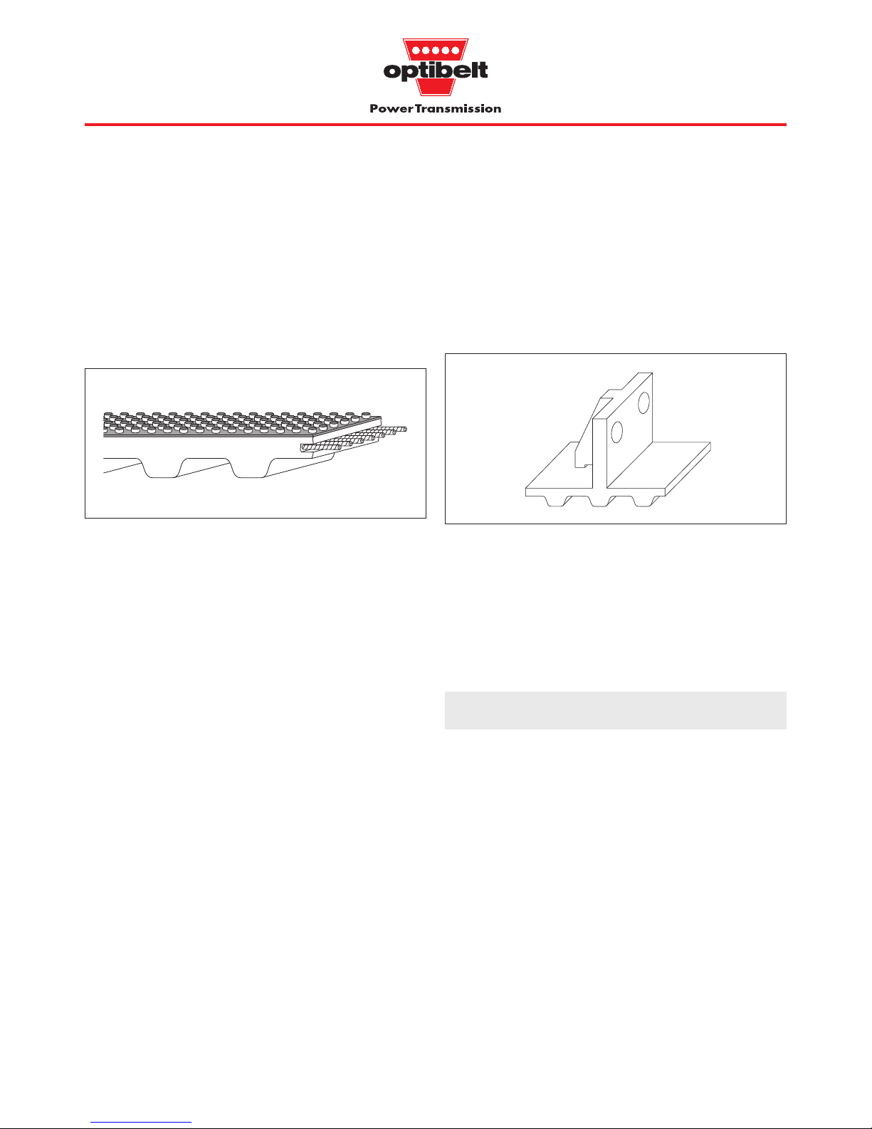
Additional top surfaces
The top surface materials listed in Table 1.4 on page 9 improve
conveying rates by increasing the coefficient of friction. They also
protect the top surface of the belt. They allow the belt to be used
on a small incline or on a haul-off arrangement in which the belt is
used to overcome level differences. Where stringent demands are
made on the uniformity of the surface or thickness, the top surface
can also be ground.
Fig.1.7: Additional top surfaces e.g. studs, white
Conveyor cleats
The belts in the Optibelt programme can be fitted with conveyor
cleats. Like the timing belt, they are made of polyurethane and are
welded to the back of the belt.
By making positive contact with the transported goods, the conveyor cleats extend the range of applications for ZRL timing belting
as follows:
● uniform feed e.g. for production and assembly lines
● conveying of bulky items using belts running in
parallel
● inclined and vertical conveying to bridge differences
in levels
● positioning and switching in handling and control
systems
1 Product Description
1.4 Special constructions
The shapes and sizes of the cleats are adapted to the function they
are required to carry out. They can, for example, be provided with
holes if fixtures are to be attached e.g. for vertical conveying.
Cleats with V-shaped grooves on their upper faces are suitable for
conveying in longitudinal and transverse directions.
Fig.1.8: Cleats with unwelded back supports for large loads and
with holes for fixtures
Cleats should be narrow in the area of the weld and are usually
arranged opposite a belt tooth. The original flexibility of the timing
belt is thus retained. In order to achieve this, the required cleat
spacing a
m
must coincide with the tooth pitch t, and the belt length
L
w
must be matched to the number nm of cleats required for the
length of the conveyor in question. With particularly long timing
belts, the length tolerance of the belt must be taken into consideration (see Table 5.2, page 43).
Lw = am · n
m
am = t · x x total number of teeth

12
dnasnoitidnocecivreS
srevomemirpfoselpmaxesrevomemirpfoselpmaxe
srevomemirpfoselpmaxe
srevomemirpfoselpmaxesrevomemirpfoselpmaxe
h61otpuh61revoh61otpuh61revo
3.14.14.15.1
6.17.18.19.1
8.19.10.21.2
0.21.22.23.2
Total service factor c
2
The total service factor comprises the basic service factor c0 and
two further correction factors c
6
and c8.
Basic service factor c
0
The basic service factor c0 takes into account the daily duration of
operation, the type of prime mover and the type of driven machine.
As it is virtually impossible to cover every combination of prime
mover/machine/operating condition in a single standardised
summary, the basic service factors must be taken as guides only.
The final drive will depend upon the loads involved in each case.
Table 2.1: Basic service factor c
0
Type of service and examples of
machine applications
Service factor c
0
at number of operating hours per day
Very heavy duty drives, continuous
operation with high shock loading
Grinding mills
Calenders
Extruders
Piston pumps and compressors
Lifting gear
Heavy duty drives, intermittent
operation with medium to high
shock loading
Machine tools
Woodworking machines
Eccentric drives
Belt conveyor systems (heavy goods)
Medium drives, intermittent operation
with low to medium shock loading
Mixing machines
Kitchen machines
Printing machines
Textile machines
Packaging machines
Belt conveyor systems (heavy goods)
Lightweight drives, shock-free and
steady running
Measuring equipment
Film cameras
Office machinery
Belt conveyor systems (lightweight goods)
2 Basics of Drive Design
2.1 Service factors, additional factors and formulae
c
0
Intermittent operation
Hydraulic motors
Low-speed turbines
Piston engines with small
number of cylinders
Steady operation
Electric motors
High-speed turbines
Piston engines with large
number of cylinders
c2 = c0 + c6 + c
8

13
Correction factors c6 and c
8
Like the basic service factor c0, the factors to be added for pulleys
and idlers c
6
and for start/stop frequency under load c8 are to be
taken as approximations only. These factors are allowances to
be made for unusual operating conditions and are added where
applicable to the basic service factor c
0
.
Table 2.2: Correction factors c6 and c8 for special operating
conditions
Type of operating Designation and Remarks
conditions value of
correction factor
Use of c
6
= 0.2 0.2 per idler
tensioning and to a maximum of
guide idlers 1.0
Start/stop c
8
= 0.1 ... 0.3 depending upon
and/or frequency, up to
reversing approx. 1.5 times
under load nominal torque
with low start-up
torque (e.g. star/
delta connection)
c8 = 0.3 ... 0.5 depending upon
frequency, above
approx. 1.5 times
nominal torque
with high start-up
torque
The correction factor c
6
applies when more than two pulleys are
used. Such use of additional pulleys must be separately checked at
the design stage.
Large drive torque of inertia should be classified as external loads.
2 Basics of Drive Design
2.1 Service factors, additional factors and formulae
Length factor c3 for ZRM/ZRP belts
The approximate values for the length factor c3 are given in
Table 2.3 and apply only to rotating highly loaded drives fitted
with ZRM/ZRP timing belts.
The length factor c
3
takes into account the increase or decrease of
belt flexing when using a short or long belt.
Note the units used for the individual parts of the formulae. The formulae for the driven torque and driven power also apply for the driver
side using the formula symbols M
An
, PAn, dw1 and n1 in place of MAb, PAb, dw2 and n
2eff
.
General
For i = 1 or z = z
1
= z
2
Formulae for explanation of symbols see page 14
v
eff
==
i
eff
=== i =
d
w1
=d
w2
= (mm)
M
Ab
= (Nm) PAb = (kW)
M
Ab
= (Nm) PAb = (kW)
M
Ab
= (Nm) PAb = (kW)
MAb · n
2eff
9550
Sn3 · dw2 · n
2eff
19100 · 1000
Sn3 · v
eff
1000
Generaldriven torque and driven power
dw2 · S
n3
2000
9550 · P
Ab
n
2eff
dw2 · P
Ab
2 · v
eff
dw1 · n
1
19100
z1 · t
π
dw2 · n
2eff
19100
z2 · t
π
Drive calculation ZRM/ZRP see page 26
Drive calculation ZRL-M see page 34
Drive calculation ZRL-V see page 37
m
s
( )
Lw = 2 · a
nom
+ z · t (mm) a
nom
= t (mm) zR=
zR – z
2
L
w
t
z
2
z
1
d
w2
d
w1
n
1
n
2eff
n
1
n
2
Table 2.3: Length factor c3 for ZRM/ZRP belts
Section Pitch length L
w
Length factor
(mm) c
3
MXL; T2.5 ≤ 190 0.8
> 190 ≤ 260 0.9
> 260 ≤ 400 1.0
> 400 1.1
XL; T5 (D); AT5 ≤ 440 0.8
> 440 ≤ 555 0.9
> 555 ≤ 800 1.0
> 800 1.1
L; T10 (D); AT10 ≤ 600 0.8
> 600 ≤ 920 0.9
> 920 ≤ 1500 1.0
> 1500 1.1
T20 (D); AT20 ≤ 1260 0.8
> 1260 ≤ 1880 0.9
> 1880 ≤ 3000 1.0
> 3000 1.1
14
2 Basics of Drive Design
2.2 Symbols used in formulae
Table 2.4 defines the essential parameters and relevant units used
in the formulae listed on page 13, and the drive design process.
Table 2.4: Symbols
Symbol Description Unit
a Required drive centre distance (mm)
a
nom
Drive centre distance with standard belt length (mm)
b
St
Standard belt width (mm)
b
th
Theoretical belt width (mm)
cvTension factor
c
0
Basic service factor
c
2
Total service factor
c
2vorh
Actual service factor
c
3
Length factor
c
6
Pulley and idler correction factor
c8Correction factor for start/stop and
reversing under load
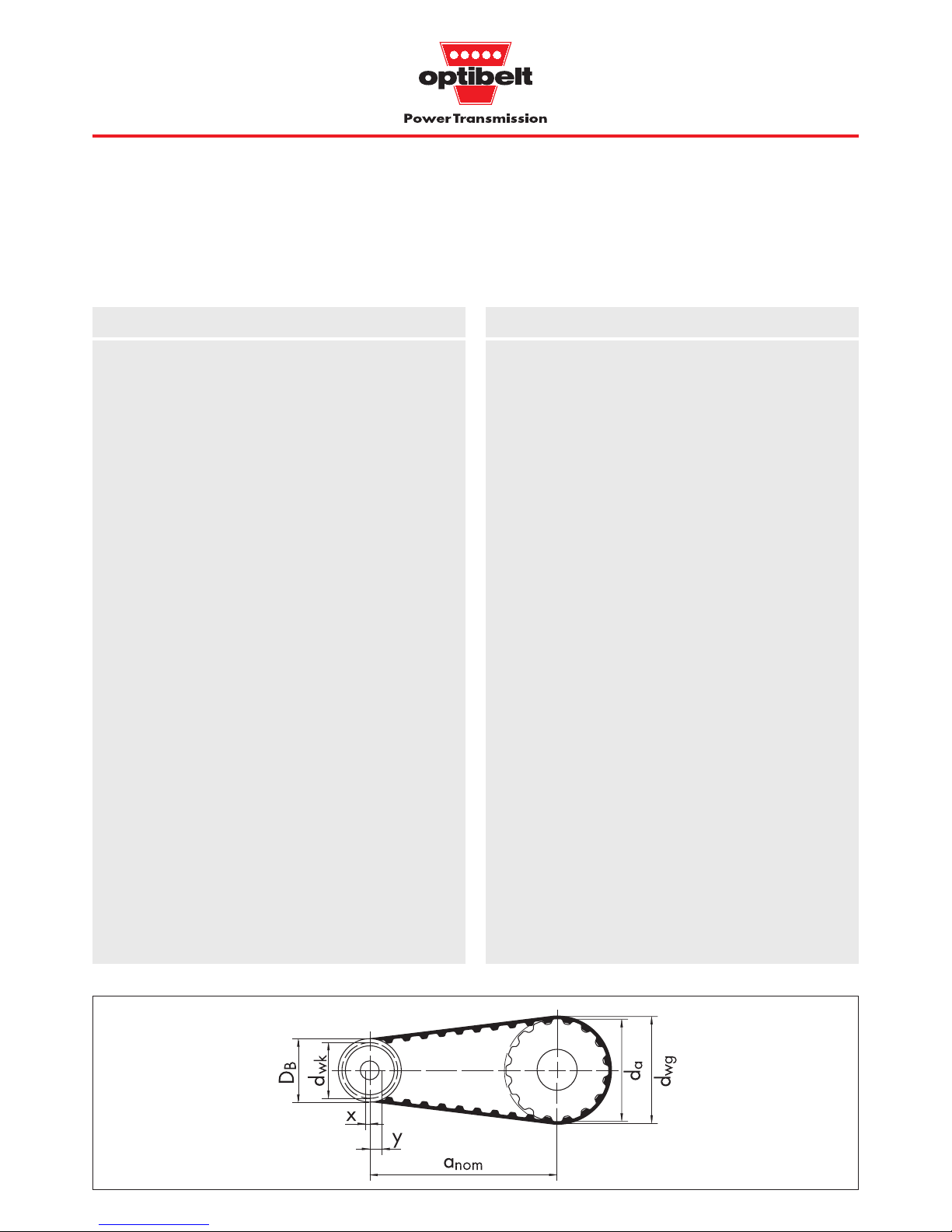
daOutside diameter of pulley (mm)
D
B
Outside diameter of pulley over flanges (mm)
d
wg
Pitch diameter of the large pulley (mm)
dwkPitch diameter of the small pulley (mm)
d
w1
Pitch diameter of the driver pulley (mm)
d
w1th
Theoretical pitch diameter of the driver pulley (mm)
d
w2
Pitch diameter of the driven pulley (mm)
e
v
Belt deflection for checking belt tension (mm)
FvLoad used to set belt tension (N)
i Ratio required
i
eff
Ratio calculated from the number of pulley teeth
L Span length (mm)
L
wnom
Pitch length of joined endless/open ended (mm)
timing belts (ZRL-V/ZRL-M)
L
wSt
Standard pitch length of endless (mm)
timing belts (ZRM/ZRP)
L
wth
Theoretical pitch length of timing belts (mm)
M
Ab
Torque (Nm)
M
Abth
Theoretical torque (Nm)
M
An
Driver torque (Nm)
M
B
Design torque including service factor (Nm)
M
Bth
Theoretical design torque (Nm)
M
spez
Transferrable torque per engaged tooth (Nm/cm)
and 10 mm belt width
n
k
Speed of small pulley (min-1)
n
1
Speed of driver pulley (min-1)
n
2
Required speed of driven pulley (min-1)
n
2eff
Speed of driven pulley calculated from (min-1)
the number of teeth
P
An
Driver power (kW)
P
Ab
Driven power (kW)
P
B
Design power including total service factor (kW)
P
spez
Power per engaged tooth, 10 mm belt width (W/cm)
and 1 tooth of the small pulley
S
a
Static shaft loading at correct tension (N)
S
Bn3
Design circumferential force including (N)
total service factor
S
n3
Circumferential force (N)
S
spez
Transferrable circumferential force per (N)
engaged tooth and 10 mm belt width
S
zul
Transferrable circumferential force at (N)
maximum standard width
t Tooth spacing (mm)
v Required belt speed (m/s)
v
eff
Actual speed (m/s)
x Allowance for centre distance adjustment (mm)
a
nom
for belt tensioning
x
v
Deflection at correct tension (ZRL-M/ZRL-V) (mm)
y
1/2/3
Allowance for centre distance adjustment (mm)
a
nom
for belt installation, determined from
pulley arrangement
z
e
Number of teeth in mesh with the small pulley –
for power transmission calculation
z
emax
Maximum number of teeth in mesh with the small
pulley – for power transmission calculation
z
enom
Number of teeth in mesh with the small pulley – actual
z
k
Number of teeth on the small pulley
z
R
Number of teeth on the timing belt
z
1
Number of teeth on the driver pulley
z2Number of teeth on the driven pulley
Symbol Description Unit
Fig.2.1: Drive arrangement
•
•
•
•
•
••
•
•
•
•
•
•
•
•
••
•
•
•
•
•
•
•
•
•
•
•

15
The data given on the chemical resistance of the Optibelt ZRM/ZRP
timing belts refers to the material polyurethane and is based on
laboratory figures arrived at under ideal conditions.
Classification of chemical resistance
1. No impairment of physical properties and working life
2. Minor impairment of physical properties and working life
3. Clearly visible swelling/disintegration, reduced physical
properties and shortened working life
4. Rapid disintegration
Copper sulphate, aqueous solution 20 1
Methanol 20 4
Methanol/petrol mixture 15 : 85 20 4
Methylene chloride 20 3
Methylethylketone 20 4
Mineral oil 80 3
n-Heptane 20 1
n-Hexane 50 1
Naphtha 20 2
Sodium carbonate,
saturated aqueous solution 20 2
Sodium chloride,
saturated aqueous solution 20 2
Sodium hydroxide, 1-N aqueous solution 20 2
Sodium phosphate, aqueous solution 20 1
Sodium soap, 20% aqueous solution 80 4
Sodium soap fat 20 3
Oleic acid 20 1
Palmitic acid 20 1
Phosphoric acid,
20-70% aqueous solution 20 1
Phosphoric acid, 85% aqueous solution 20 3
Mercury 20 1
SAE-10 oil 70 1
Nitric acid, 20% aqueous solution 20 4
Hydrochloric acid, 20% aqueous solution 20 2
Hydrochloric acid, 37% aqueous solution 20 4
Grease 20 2
Sulphuric acid, 20% aqueous solution 20 4
Sulphuric acid, 5% aqueous solution 20 2
Sulphurous acid 20 4
Seawater 20 2
Soap solution, aqueous 20 1
Soya oil 20 1
Stearic acid 20 1
Tannic acid, 10% aqueous solution 20 1
Turpentine 20 4
Carbon tetrachloride 20 4
Tetrahydrofuran 20 4
Toluol 20 4
Trichlorethane 20 4
Tricresyl phosphate 20 2
Water 100 4
Water 90 3
Water 20 1
Hydrogen 20 1
Plasticising oils 20 2
Xylol 20 4
3.1 ZRM/ZRP resistance to chemicals
Resistance of endless
optibelt
ZRM/ZRP timing belts
Table 3.1: ZRM/ZRP chemical resistance
Aluminium chloride,
5% aqueous solution 20 2
Formic acid 20 4
Ammonia 10% aqueous solution 20 2
Aniline 20 4
ASTM oil No. 1 80 3
ASTM oil No. 2 80 3
ASTM oil No. 3 80 3
Acetone 20 4
Petrol, “normal” 20 3
Petrol, “super” 20 3
Benzol 20 4
Borax solution 20 1
Boric acid, aqueous solution 20 1
Butane 20 1
Butanol 20 2
Butyl acetate 20 4
Calcium chlorate (I),
5% aqueous solution 20 4
Calcium chloride, aqueous solution 20 1
Calcium hydrogen sulphide,
aqueous solution 20 1
Chlorine, gaseous 20 4
Chromic acid
10 : 50% aqueous solution 20 4
Cyclohexane 20 2
Cyclohexanol 20 1
Diesel fuel 20 2
Dimethyl formamide 20 4
Ferric (III) chloride, 5% aqueous solution 40 3
Acetic acid, 20% aqueous solution 20 3
Ethanol 20 3
Ethyl acetate 20 4
Ethyl ether 20 3
Formaldehyde, 37% aqueous solution 20 3
Freon-11 20 2
Freon-113 20 1
Freon-12 54 1
Freon-22 20 3
Glycerine 20 1
Hydraulic fluid 20 2
Iso-octane 70 1
Iso-propanol 20 3
Potassium hydroxide,
1-N aqueous solution 20 3
Kerosene 20 2
Carbon dioxide 20 1
Copper chloride, aqueous solution 20 1
Medium
Temperatur
(°C)
Beständig-
keit
Medium
Temperatur
(°C)
Beständig-
keit
16
–5.2TnoitceS
mm5.2hctipmm5.2hctip
mm5.2hctip
mm5.2hctipmm5.2hctip
mm5hctip–5TnoitceS mm01hctip–01TnoitceS
.oNtleB
hctiP
)mm(
.oN
hteetfo.oNtleB
hctiP
)mm(
.oN
hteetfo.oNtleB
hctiP
)mm(
.oN
hteetfo.oNtleB
hctiP
)mm(
.oN
hteetfo
Standard widths bSt (mm):
4, 6, 8, 10, 12
Standard widths bSt (mm):
6, 8, 10, 12, 16, 20, 25
Standard widths bSt (mm):
10, 12, 16, 20, 25, 32, 50
3.2 ZRM/ZRP timing belt range
optibelt
ZRM timing belts, metric sizes
Further sizes on request. * Non stock
Section Pitch Tooth Overall Tooth Tooth
depth belt width angle
thickness
th
t
h
s
s2 β
(mm) (mm) (mm) (mm) (°)
T2.5 2.5 0.70 1.30 1.50 40
T5 5.0 1.20 2.20 2.65 40
T10 10.0 2.50 4.50 5.30 40
Construction: polyurethane with steel tension cord
Table 3.2: ZRM timing belt range
L
wSt
T2.5/120 120.0 48
T2.5/160 160.0 64
T2.5/177.5 177.5 71
T2.5/200 200.0 80
T2.5/230 230.0 92
T2.5/245 245.0 98
T2.5/265 265.0 106
T2.5/285 285.0 114
T2.5/305 305.0 122
T2.5/317.5 317.5 127
T2.5/330 330.0 132
T2.5/380 380.0 152
T2.5/420 420.0 168
T2.5/480 480.0 192
T2.5/500 500.0 200
T2.5/540 540.0 216
T2.5/600 600.0 240
T2.5/650 650.0 260
T2.5/780 780.0 312
T2.5/915 915.0 366
T2.5/950 950.0 380
T5/165 165.0 33
T5/185 185.0 37
T5/200 200.0 40
T5/215 215.0 43
T5/220 220.0 44
T5/225 225.0 45
T5/245 245.0 49
T5/250 250.0 50
T5/255 255.0 51
T5/260 260.0 52
T5/270 270.0 54
T5/275 275.0 55
T5/280 280.0 56
T5/295 295.0 59
T5/300 300.0 60
T5/305 305.0 61
T5/325 325.0 65
T5/330 330.0 66
T5/340 340.0 68
T5/350 350.0 70
T5/355 355.0 71
T5/360* 360.0 72
T5/365 365.0 73
T5/375 375.0 75
T5/390 390.0 78
T5/400 400.0 80
T5/410 410.0 82
T5/420 420.0 84
T5/425 425.0 85
T5/440* 440.0 88
T5/445* 445.0 89
T5/450 450.0 90
T5/455 455.0 91
T5/460* 460.0 92
T5/475 475.0 95
T5/480 480.0 96
T5/500 500.0 100
T5/510 510.0 102
T5/525 525.0 105
T5/545 545.0 109
T5/ 550 550.0 110
T5/ 560 560.0 112
T5/ 575 575.0 115
T5/ 590* 590.0 118
T5/ 600 600.0 120
T5/ 610 610.0 122
T5/ 620 620.0 124
T5/ 625* 625.0 125
T5/ 630 630.0 126
T5/ 640 640.0 128
T5/ 650 650.0 130
T5/ 660 660.0 132
T5/ 675* 675.0 135
T5/ 690 690.0 138
T5/ 700 700.0 140
T5/ 720 720.0 144
T5/ 725 725.0 145
T5/ 750 750.0 150
T5/ 780 780.0 156
T5/ 800* 800.0 160
T5/ 815 815.0 163
T5/ 840 840.0 168
T5/ 850 850.0 170
T5/ 860* 860.0 172
T5/ 900 900.0 180
T5/ 940 940.0 188
T5/ 990 990.0 198
T5/1000 1000.0 200
T5/1075 1075.0 215
T5/1100 1100.0 220
T5/1115* 1115.0 223
T5/1140* 1140.0 228
T5/1215 1215.0 243
T5/1350* 1350.0 270
T5/1380 1380.0 276
T5/1440 1440.0 288
T10/ 260 260.0 26
T10/ 370 370.0 37
T10/ 400 400.0 40
T10/ 410 410.0 41
T10/ 440 440.0 44
T10/ 450 450.0 45
T10/ 500 500.0 50
T10/ 530 530.0 53
T10/ 550* 550.0 55
T10/ 560 560.0 56
T10/ 600 600.0 60
T10/ 610 610.0 61
T10/ 630 630.0 63
T10/ 650 650.0 65
T10/ 660 660.0 66
T10/ 690 690.0 69
T10/ 700 700.0 70
T10/ 720 720.0 72
T10/ 750 750.0 75
T10/ 780 780.0 78
T10/ 800* 800.0 80
T10/ 810 810.0 81
T10/ 840 840.0 84
T10/ 850* 850.0 85
T10/ 880 880.0 88
T10/ 890 890.0 89
T10/ 900 900.0 90
T10/ 910 910.0 91
T10/ 920 920.0 92
T10/ 950 950.0 95
T10/ 960 960.0 96
T10/ 970 970.0 97
T10/ 980 980.0 98
T10/1000* 1000.0 100
T10/1010 1010.0 101
T10/1050 1050.0 105
T10/1080 1080.0 108
T10/1100 1100.0 110
T10/1110 1110.0 111
T10/1140 1140.0 114
L
wSt
L
wSt
L
wSt
z
R
z
R
z
R
z
R
Order example for ZRM: 10 T2.5/200
Width (mm)
Section
Pitch length (mm)
•
•
•
•
•••••••
•
17
deunitnoc,01TnoitceSmm5hctip–D5TnoitceSmm01hctip–D01TnoitceS
.oNtleB
hctiP
)mm(
.oN
hteetfo.oNtleB
hctiP
)mm(
.oN
hteetfo.oNtleB
hctiP
)mm(
.oN
hteetfo
Standard widths bSt (mm):
10, 12, 16, 20, 25, 32, 50
Standard widths bSt (mm):
6, 8, 10, 12, 16, 20, 25
Standard widths bSt (mm):
10, 12, 16, 20, 25, 32, 50
Section Pitch Tooth Overall Tooth Tooth
depth belt width angle
thickness
th
t
hs1s2 β
(mm) (mm) (mm) (mm) (°)
T5D 5.0 1.20 3.40 2.65 40
T10D 10.0 2.50 7.00 5.30 40
3.2 ZRM/ZRP timing belt range
optibelt
ZRM double section timing belts, metric sizes
Further sizes on request. * Non stock
Table 3.2 continued
L
wSt
z
R
L
wSt
z
R
z
R
L
wSt
T10/1150 1150.0 115
T10/1200 1200.0 120
T10/1210 1210.0 121
T10/1240 1240.0 124
T10/1250 1250.0 125
T10/1300 1300.0 130
T10/1320 1320.0 132
T10/1350 1350.0 135
T10/1390 1390.0 139
T10/1400 1400.0 140
T10/1420 1420.0 142
T10/1440 1440.0 144
T10/1450 1450.0 145
T10/1460 1460.0 146
T10/1500 1500.0 150
T10/1560 1560.0 156
T10/1600 1600.0 160
T10/1610 1610.0 161
T10/1700 1700.0 170
T10/1750 1750.0 175
T10/1780 1780.0 178
T10/1800* 1800.0 180
T10/1880 1880.0 188
T10/1960 1960.0 196
T10/2250 2250.0 225
T5/ 300 D* 300.0 60
T5/ 350 D* 350.0 70
T5/ 400 D* 400.0 80
T5/ 410 D 410.0 82
T5/ 450 D* 450.0 90
T5/ 460 D 460.0 92
T5/ 480 D 480.0 96
T5/ 500 D 500.0 100
T5/ 515 D 515.0 103
T5/ 550 D 550.0 110
T5/ 590 D 590.0 118
T5/ 600 D* 600.0 120
T5/ 620 D 620.0 124
T5/ 650 D 650.0 130
T5/ 700 D 700.0 140
T5/ 750 D 750.0 150
T5/ 800 D 800.0 160
T5/ 815 D 815.0 163
T5/ 850 D* 850.0 170
T5/ 860 D 860.0 172
T5/ 900 D 900.0 180
T5/ 940 D 940.0 188
T5/1100 D 1100.0 220
T10/ 260 D 260.0 26
T10/ 530 D 530.0 53
T10/ 600 D 600.0 60
T10/ 630 D 630.0 63
T10/ 660 D 660.0 66
T10/ 700 D 700.0 70
T10/ 720 D 720.0 72
T10/ 750 D 750.0 75
T10/ 800 D 800.0 80
T10/ 840 D 840.0 84
T10/ 900 D 900.0 90
T10/ 980 D 980.0 98
T10/1000 D* 1000.0 100
T10/1100 D 1100.0 110
T10/1200 D* 1200.0 120
T10/1210 D 1210.0 121
T10/1240 D 1240.0 124
T10/1250 D 1250.0 125
T10/1300 D* 1300.0 130
T10/1320 D 1320.0 132
T10/1350 D 1350.0 135
T10/1400 D 1400.0 140
T10/1420 D 1420.0 142
T10/1500 D 1500.0 150
T10/1600 D* 1600.0 160
T10/1610 D 1610.0 161
T10/1700 D 1700.0 170
T10/1800 D 1800.0 180
T10/1880 D 1880.0 188
Order example for ZRM D: 50 T 10/1420 D
Width (mm)
Section
Pitch length (mm)
Double section timing belts
T20 and AT sizes
on request
Construction:
polyurethane with steel tension cord
•
•
•
••
•• •
•
•
•
•
•
•
•
18
mm230.2hctip–*LXMnoitceS mm80.5hctip–LXnoitceS
.oNtleB
.oN
hteetfo.oNtleB
.oN
hteetfo.oNtleB
.oN
hteetfo
)hcni()mm()hcni()mm()hcni()mm(
Further sizes on request. * Non stock: minimum order 1 sleeve
3.2 ZRM/ZRP timing belt range
optibelt
ZRP timing belts, inch sizes
Section Pitch Tooth Overall Tooth Tooth
depth belt width angle
thickness
th
t
h
s
s2 β
(mm) (mm) (mm) (mm) (°)
MXL 2.032 0.51 1.14 1.14 40
XL 5.080 1.27 2.30 2.57 50
L 9.525 1.91 3.60 4.65 40
Table 3.3: ZRP timing belt range
Construction: polyurethane with Aramid (MXL) or steel tension cord (XL, L)
K 240 MXL 2.40 60.96 30
K 280 MXL 2.80 71.12 35
K 320 MXL 3.20 81.28 40
K 360 MXL 3.60 91.44 45
K 400 MXL 4.00 101.60 50
K 440 MXL 4.40 111.76 55
K 480 MXL 4.80 121.92 60
K 520 MXL 5.20 132.08 65
K 560 MXL 5.60 142.24 70
K 600 MXL 6.00 152.40 75
K 640 MXL 6.40 162.56 80
K 680 MXL 6.80 172.72 85
K 720 MXL 7.20 182.88 90
K 760 MXL 7.60 193.04 95
K 800 MXL 8.00 203.20 100
K 840 MXL 8.40 213.36 105
K 880 MXL 8.80 223.52 110
K 920 MXL 9.20 233.68 115
K 960 MXL 9.60 243.84 120
K 1000 MXL 10.00 254.00 125
K 1040 MXL 10.40 264.16 130
K 1080 MXL 10.80 274.32 135
K 1120 MXL 11.20 284.48 140
K 1160 MXL 11.60 294.64 145
K 1200 MXL 12.00 304.80 150
K 1240 MXL 12.40 314.96 155
K 1280 MXL 12.80 325.12 160
K 1320 MXL 13.20 335.28 165
K 1360 MXL 13.60 345.44 170
K 1400 MXL 14.00 355.60 175
K 1440 MXL 14.40 365.76 180
K 1480 MXL 14.80 375.92 185
K 1520 MXL 15.20 386.08 190
K 1560 MXL 15.60 396.24 195
K 1600 MXL 16.00 406.40 200
K 1640 MXL 16.40 416.56 205
K 1680 MXL 16.80 426.72 210
K 1720 MXL 17.20 436.88 215
K 1760 MXL 17.60 447.04 220
K 1800 MXL 18.00 457.20 225
K 1840 MXL 18.40 467.36 230
K 1880 MXL 18.80 477.52 235
K 1920 MXL 19.20 487.68 240
K 1960 MXL 19.60 497.84 245
K 2000 MXL 20.00 508.00 250
K 2040 MXL 20.40 518.16 255
K 2080 MXL 20.80 528.32 260
K 2120 MXL 21.20 538.48 265
K 2160 MXL 21.60 548.64 270
K 2200 MXL 22.00 558.80 275
K 2240 MXL 22.40 568.96 280
K 2280 MXL 22.80 579.12 285
K 2320 MXL 23.20 589.28 290
K 2360 MXL 23.60 599.44 295
K 2400 MXL 24.00 609.60 300
K 2480 MXL 24.80 629.92 310
K 2560 MXL 25.60 650.24 320
K 2640 MXL 26.40 670.56 330
K 2720 MXL 27.20 690.88 340
K 2800 MXL 28.00 711.20 350
K 2880 MXL 28.80 731.52 360
K 2960 MXL 29.60 751.84 370
K 3040 MXL 30.40 772.16 380
K 3120 MXL 31.20 792.48 390
K 3200 MXL 32.00 812.80 400
z
R
Pitch length
L
wSt
z
R
Pitch length
L
wSt
z
R
Pitch length
L
wSt
K 60 XL* 6.00 152.40 30
K 70 XL* 7.00 177.80 35
K 76 XL* 7.60 193.04 38
K 80 XL* 8.00 203.20 40
K 84 XL* 8.40 213.36 42
K 90 XL* 9.00 228.60 45
K 94 XL* 9.40 238.76 47
K 96 XL* 9.60 243.84 48
K 100 XL 10.00 254.00 50
K 102 XL* 10.20 259.08 51
K 104 XL* 10.40 264.16 52
K 106 XL* 10.60 269.24 53
K 110 XL 11.00 279.40 55
K 114 XL* 11.40 289.56 57
K 116 XL* 11.60 294.64 58
K 120 XL 12.00 304.80 60
K 124 XL* 12.40 314.96 62
K 126 XL* 12.60 320.04 63
K 128 XL* 12.80 325.12 64
K 130 XL 13.00 330.20 65
K 136 XL* 13.60 345.44 68
K 140 XL 14.00 355.60 70
K 150 XL 15.00 381.00 75
K 152 XL* 15.20 386.08 76
K 154 XL* 15.40 391.16 77
K 160 XL 16.00 406.40 80
K 166 XL* 16.60 421.64 83
K 170 XL 17.00 431.80 85
K 180 XL 18.00 457.20 90
K 186 XL* 18.60 472.44 93
K 190 XL 19.00 482.60 95
K 200 XL 20.00 508.00 100
K 210 XL 21.00 533.40 105
K 212 XL* 21.20 538.48 106
K 220 XL 22.00 558.80 110
K 230 XL 23.00 584.20 115
K 240 XL 24.00 609.60 120
K 250 XL 25.00 635.00 125
K 254 XL* 25.40 645.16 127
K 260 XL 26.00 660.40 130
Sleeve width: 127 ± 10 mm
Order example for ZRP: K 120 XL 037
K = plastic
(polyurethane)
Pitch length code
Pitch length (inch x 10)
Section
Width code
Width (inch x 100)
Standard widths bSt:
1/8" = 3.175 mm 3/16" = 4.764 mm 1/4" = 6.35 mm 5/16" = 7.94 mm
Code No.:
012 019 025 031
Standard widths bSt, continued on page 19:
1/4" = 6.35 mm 5/16" = 7.94 mm
Code No.:
025 031
•
•
•
•
•••••••
•

19
3.2 ZRM/ZRP Timing Belt Range
optibelt
ZRP timing belts, inch sizes
Section Pitch Tooth Overall Tooth Tooth
depth belt width angle
thickness
th
t
h
s
s2 β
(mm) (mm) (mm) (mm) (°)
MXL 2.032 0.51 1.14 1.14 40
XL 5.080 1.27 2.30 2.57 50
L 9.525 1.91 3.60 4.65 40
Further sizes on request. * Non stock: minimum order 1 sleeve
Table 3.3, continued:
Construction: polyurethane with Aramid (MXL) or steel tension cord (XL, L)
K 270 XL 27.00 685.80 135
K 290 XL 29.00 736.60 145
K 300 XL 30.00 762.00 150
K 320 XL* 32.00 812.80 160
K 330 XL 33.00 838.20 165
K 360 XL* 36.00 914.40 180
K 376 XL* 37.60 955.04 188
K 384 XL* 38.40 975.36 192
K 390 XL 39.00 990.60 195
K 414 XL* 41.40 1051.56 207
K 460 XL* 46.00 1168.40 230
K 480 XL* 48.00 1219.20 240
K 512 XL* 51.20 1300.48 256
K 550 XL* 55.00 1397.00 275
K 564 XL* 56.40 1432.56 282
K 630 XL* 63.00 1600.20 315
K 670 XL* 67.00 1701.80 335
K 124 L 12.40 314.30 33
K 150 L 15.00 381.00 40
K 165 L* 16.50 419.10 44
K 173 L* 17.30 439.42 46
K 187 L 18.70 476.20 50
K 210 L 21.00 533.40 56
K 225 L 22.50 571.50 60
K 240 L 24.00 609.60 64
K 255 L 25.50 647.70 68
K 270 L 27.00 685.80 72
K 285 L 28.50 723.90 76
K 300 L 30.00 762.00 80
K 322 L 32.20 819.10 86
K 345 L 34.50 876.30 92
K 367 L 36.70 933.40 98
K 375 L* 37.50 952.50 100
K 390 L 39.00 990.60 104
K 420 L 42.00 1066.80 112
K 427 L* 42.70 1084.58 114
K 450 L 45.00 1143.00 120
K 480 L 48.00 1219.20 128
K 510 L 51.00 1295.40 136
K 525 L* 52.50 1333.50 140
K 540 L 54.00 1371.60 144
K 600 L 60.00 1524.00 160
Pitch length
L
wSt
z
R
Pitch length
L
wSt
z
R
Sleeve width: 150 ± 10 mmSleeve width: 150 ± 10 mm
Order example for ZRP: K 480 L 150
K = plastic
(polyurethane)
Pitch length code
Pitch length (inch x 10)
Section
Width code
Width (inch x 100)
Standard widths bSt, continued for page 18:
3/8" = 9.53 mm 1/2" = 12.7 mm
Code No.:
037 050
Standard widths bSt:
1/2" = 12.7 mm 3/4" = 19.05 mm 1" = 25.4 mm 1 1/2" = 38.1 mm
Code No.:
050 075 100 150
•
•
•
•
•••••••
•
deunitnoc,mm80.5hctip–LXnoitceS mm525.9hctip–LnoitceS
.oNtleB
.oN
hteetfo.oNtleB
.oN
hteetfo
)hcni()mm()hcni()mm(
20
Type AT5 – pitch 5 mm
Belt No.
Pitch length
(mm)
Number
of teeth
Belt No.
Pitch length
(mm)
Number
of teeth
Type AT10 – pitch 10 mm
Standard widths:
6 mm – Code 6; 8 mm – Code 8; 10 mm – Code 10; 12 mm – Code 12;
16 mm – Code 16; 20 mm – Code 20; 25 mm – Code 25.
Standard widths:
10 mm – Code 10; 12 mm – Code 12; 16 mm – Code 16; 20 mm – Code 20;
25 mm – Code 25; 32 mm – Code 32; 50 mm – Code 50.
Construction: polyurethane with steel-wire cord
AT5 / AT10
10 /AT5 300
Type
ββ
ββ
β
AT5 5.0 1.20 2.70 2.50 50°
AT10 10.0 2.50 5.00 5.00 50°
th
t
hsb
(mm) (mm) (mm) (mm)
Pitch length (mm)
Pitch (5␣ mm)
Width (mm)
Further sizes on request.
AT5/ 225 225.00 45
AT5/ 255 255.00 51
AT5/ 280 280.00 56
AT5/ 300 300.00 60
AT5/ 340 340.00 68
AT5/ 375 375.00 75
AT5/ 390 390.00 78
AT5/ 420 420.00 84
AT5/ 450 450.00 90
AT5/ 455 455.00 91
AT5/ 500 500.00 100
AT5/ 545 545.00 109
AT5/ 600 600.00 120
AT5/ 610 610.00 122
AT5/ 660 660.00 132
AT5/ 710 710.00 142
AT5/ 720 720.00 144
AT5/ 750 750.00 150
AT5/ 780 780.00 156
AT5/ 825 825.00 165
AT5/ 860 860.00 172
AT5/ 975 975.00 195
AT5/1050 1050.00 210
AT5/1125 1125.00 225
AT5/1500 1500.00 300
AT10/ 500 500.00 50
AT10/ 560 560.00 56
AT10/ 600 600.00 60
AT10/ 610 610.00 61
AT10/ 660 660.00 66
AT10/ 700 700.00 70
AT10/ 730 730.00 73
AT10/ 780 780.00 78
AT10/ 800 800.00 80
AT10/ 840 840.00 84
AT10/ 890 890.00 89
AT10/ 920 920.00 92
AT10/ 960 960.00 96
AT10/ 980 980.00 98
AT10/1000 1000.00 100
AT10/1010 1010.00 101
AT10/1050 1050.00 105
AT10/1080 1080.00 108
AT10/1100 1100.00 110
AT10/1150 1150.00 115
AT10/1200 1200.00 120
AT10/1210 1210.00 121
AT10/1250 1250.00 125
AT10/1280 1280.00 128
AT10/1300 1300.00 130
AT10/1320 1320.00 132
AT10/1350 1350.00 135
AT10/1360 1360.00 136
AT10/1400 1400.00 140
AT10/1420 1420.00 142
AT10/1480 1480.00 148
AT10/1500 1500.00 150
AT10/1600 1600.00 160
AT10/1700 1700.00 170
AT10/1720 1720.00 172
AT10/1800 1800.00 180
AT10/1860 1860.00 186
AT10/1940 1940.00 194
3.2 ZRM/ZRP timing belt range
optibelt
ZRM timing belts, metric
Table 3.4
21
Construction: polyurethane with steel-wire cord
5.0
1.8
1.2
2.2
10.0
3.5
2.5
4.5
20.0
6.5
5.0
8.0
Standard widths:
16 mm – Code 16; 25 mm – Code 25; 32 mm – Code 32; 50 mm – Code 50; 75 mm – Code 75; 100 mm – Code 100.
3.2 ZRM/ZRP timing belt range
optiflex
timing belts, endless manufactured
T5/1500• 1500.00 300
T5/1600• 1600.00 320
T5/1700• 1700.00 340
T5/1800• 1800.00 360
T5/1900• 1900.00 380
T5/2000• 2000.00 400
T5/2100• 2100.00 420
T5/2200• 2200.00 440
T5/2300• 2300.00 460
T5/2400• 2400.00 480
T5/2500• 2500.00 500
T5/2600• 2600.00 520
T5/2700• 2700.00 540
T5/2800• 2800.00 560
T5/2900• 2900.00 580
T5/3000• 3000.00 600
T5/3200• 3200.00 640
T5/3400• 3400.00 680
T5/3600• 3600.00 720
T5/3800• 3800.00 760
T5/4000• 4000.00 800
T5/4200• 4200.00 840
T5/4400• 4400.00 880
T5/4600• 4600.00 920
T5/4800• 4800.00 960
T5/5000• 5000.00 1000
T5/5200• 5200.00 1040
T5/5400• 5400.00 1080
T5/5600• 5600.00 1120
T5/5800• 5800.00 1160
T5/6000• 6000.00 1200
T10/1500• 1500.00 150
T10/1600• 1600.00 160
T10/1700• 1700.00 170
T10/1800• 1800.00 180
T10/1900• 1900.00 190
T10/2000• 2000.00 200
T10/2100• 2100.00 210
T10/2200• 2200.00 220
T10/2300• 2300.00 230
T10/2400• 2400.00 240
T10/2500• 2500.00 250
T10/2600• 2600.00 260
T10/2700• 2700.00 270
T10/2800• 2800.00 280
T10/2900• 2900.00 290
T10/3000• 3000.00 300
T10/3200• 3200.00 320
T10/3400• 3400.00 340
T10/3600• 3600.00 360
T10/3800• 3800.00 380
T10/4000• 4000.00 400
T10/4200• 4200.00 420
T10/4400• 4400.00 440
T10/4600• 4600.00 460
T10/4800• 4800.00 480
T10/5000• 5000.00 500
T10/5200• 5200.00 520
T10/5400• 5400.00 540
T10/5600• 5600.00 560
T10/5800• 5800.00 580
T10/6000• 6000.00 600
T20/1500• 1500.00 75
T20/1600• 1600.00 80
T20/1700• 1700.00 85
T20/1800• 1800.00 90
T20/1900• 1900.00 95
T20/2000• 2000.00 100
T20/2100• 2100.00 105
T20/2200• 2200.00 110
T20/2300• 2300.00 115
T20/2400• 2400.00 120
T20/2500• 2500.00 125
T20/2600• 2600.00 130
T20/2700• 2700.00 135
T20/2800• 2800.00 140
T20/2900• 2900.00 145
T20/3000• 3000.00 150
T20/3200• 3200.00 160
T20/3400• 3400.00 170
T20/3600• 3600.00 180
T20/3800• 3800.00 190
T20/4000• 4000.00 200
T20/4200• 4200.00 210
T20/4400• 4400.00 220
T20/4600• 4600.00 230
T20/4800• 4800.00 240
T20/5000• 5000.00 250
T20/5200• 5200.00 260
T20/5400• 5400.00 270
T20/5600• 5600.00 280
T20/5800• 5800.00 290
T20/6000• 6000.00 300
Type T5 – pitch 5 mm Type T10 – pitch 10 mm Type T20 – pitch 20 mm
Optiflex timing belts are available with PAZ fabric.
Length: 1500 mm - 24 000 mm
Minimum quantity: according to production capability (100 mm or 150 mm)
Double-toothed timing belts section T5D / T10D – on request.
Lengths over 6000 mm on request.
• Non stock items.
Belt No.
Pitch length
(mm)
Number
of teeth
Belt No.
Pitch length
(mm)
Number
of teeth
Belt No.
Pitch length
(mm)
Number
of teeth

22
Construction: polyurethane with steel-wire cord
Type AT5 – pitch 5 mm Type AT10 – pitch 10 mm Type AT20 – pitch 20 mm
5.0
2.5
1.2
2.7
10.0
5.0
2.5
4.5
20.0
10.0
5.0
8.0
Standard widths:
16 mm – Code 16; 25 mm – Code 25; 32 mm – Code 32; 50 mm – Code 50; 75 mm – Code 75; 100 mm – Code 100.
AT5/1500• 1500.00 300
AT5/1600• 1600.00 320
AT5/1700• 1700.00 340
AT5/1800• 1800.00 360
AT5/1900• 1900.00 380
AT5/2000• 2000.00 400
AT5/2100• 2100.00 420
AT5/2200• 2200.00 440
AT5/2300• 2300.00 460
AT5/2400• 2400.00 480
AT5/2500• 2500.00 500
AT5/2600• 2600.00 520
AT5/2700• 2700.00 540
AT5/2800• 2800.00 560
AT5/2900• 2900.00 580
AT5/3000• 3000.00 600
AT5/3200• 3200.00 640
AT5/3400• 3400.00 680
AT5/3600• 3600.00 720
AT5/3800• 3800.00 760
AT5/4000• 4000.00 800
AT5/4200• 4200.00 840
AT5/4400• 4400.00 880
AT5/4600• 4600.00 920
AT5/4800• 4800.00 960
AT5/5000• 5000.00 1000
AT5/5200• 5200.00 1040
AT5/5400• 5400.00 1080
AT5/5600• 5600.00 1120
AT5/5800• 5800.00 1160
AT5/6000• 6000.00 1200
AT10/1500• 1500.00 150
AT10/1600• 1600.00 160
AT10/1700• 1700.00 170
AT10/1800• 1800.00 180
AT10/1900• 1900.00 190
AT10/2000• 2000.00 200
AT10/2100• 2100.00 210
AT10/2200• 2200.00 220
AT10/2300• 2300.00 230
AT10/2400• 2400.00 240
AT10/2500• 2500.00 250
AT10/2600• 2600.00 260
AT10/2700• 2700.00 270
AT10/2800• 2800.00 280
AT10/2900• 2900.00 290
AT10/3000• 3000.00 300
AT10/3200• 3200.00 320
AT10/3400• 3400.00 340
AT10/3600• 3600.00 360
AT10/3800• 3800.00 380
AT10/4000• 4000.00 400
AT10/4200• 4200.00 420
AT10/4400• 4400.00 440
AT10/4600• 4600.00 460
AT10/4800• 4800.00 480
AT10/5000• 5000.00 500
AT10/5200• 5200.00 520
AT10/5400• 5400.00 540
AT10/5600• 5600.00 560
AT10/5800• 5800.00 580
AT10/6000• 6000.00 600
AT20/1500• 1500.00 75
AT20/1600• 1600.00 80
AT20/1700• 1700.00 85
AT20/1800• 1800.00 90
AT20/1900• 1900.00 95
AT20/2000• 2000.00 100
AT20/2100• 2100.00 105
AT20/2200• 2200.00 110
AT20/2300• 2300.00 115
AT20/2400• 2400.00 120
AT20/2500• 2500.00 125
AT20/2600• 2600.00 130
AT20/2700• 2700.00 135
AT20/2800• 2800.00 140
AT20/2900• 2900.00 145
AT20/3000• 3000.00 150
AT20/3200• 3200.00 160
AT20/3400• 3400.00 170
AT20/3600• 3600.00 180
AT20/3800• 3800.00 190
AT20/4000• 4000.00 200
AT20/4200• 4200.00 210
AT20/4400• 4400.00 220
AT20/4600• 4600.00 230
AT20/4800• 4800.00 240
AT20/5000• 5000.00 250
AT20/5200• 5200.00 260
AT20/5400• 5400.00 270
AT20/5600• 5600.00 280
AT20/5800• 5800.00 290
AT20/6000• 6000.00 300
Optiflex timing belts are available with PAZ fabric.
Length: 1500 mm - 24 000 mm
Minimum quantity: according to production capability (100 mm or 150 mm)
Double-toothed timing belts section AT5D / AT10D – on request.
Lengths over 6000 mm on request.
• Non stock items.
3.2 ZRM/ZRP timing belt range
optiflex
timing belts, endless manufactured
Belt No.
Pitch length
(mm)
Number
of teeth
Belt No.
Pitch length
(mm)
Number
of teeth
Belt No.
Pitch length
(mm)
Number
of teeth
23
Standard widths:
15 mm – Code 15; 25 mm – Code 25; 50 mm – Code 50;
75 mm – Code 75; 100 mm – Code 100.
Type 5M – pitch 5 mm
Construction: polyurethane with steel-wire cord
5.0
2.2
3.7
Type 8M – pitch 8 mm Type 14M – pitch 14 mm
8.0
3.6
5.6
14.0
6.43
10.0
Standard widths:
20 mm – Code 20; 25 mm – Code 25; 30 mm – Code 30;
50 mm – Code 50; 85 mm – Code 85; 100 mm – Code 100.
Standard widths:
25 mm – Code 25; 40 mm – Code 40; 55 mm – Code 55;
85 mm – Code 85; 100 mm – Code 100.
5M/1500• 1500.00 300
5M/1600• 1600.00 320
5M/1700• 1700.00 340
5M/1800• 1800.00 360
5M/1900• 1900.00 380
5M/2000• 2000.00 400
5M/2100• 2100.00 420
5M/2200• 2200.00 440
5M/2300• 2300.00 460
5M/2400• 2400.00 480
5M/2500• 2500.00 500
5M/2600• 2600.00 520
5M/2700• 2700.00 540
5M/2800• 2800.00 560
5M/2900• 2900.00 580
5M/3000• 3000.00 600
5M/3200• 3200.00 640
5M/3400• 3400.00 680
5M/3600• 3600.00 720
5M/3800• 3800.00 760
5M/4000• 4000.00 800
5M/4200• 4200.00 840
5M/4400• 4400.00 880
5M/4600• 4600.00 920
5M/4800• 4800.00 960
5M/5000• 5000.00 1000
5M/5200• 5200.00 1040
5M/5400• 5400.00 1080
5M/5600• 5600.00 1120
5M/5800• 5800.00 1160
5M/6000• 6000.00 1200
8M/1504• 1504.00 188
8M/1600• 1600.00 200
8M/1704• 1704.00 213
8M/1800• 1800.00 225
8M/1904• 1904.00 238
8M/2000• 2000.00 250
8M/2104• 2104.00 263
8M/2200• 2200.00 275
8M/2304• 2304.00 288
8M/2400• 2400.00 300
8M/2504• 2504.00 313
8M/2600• 2600.00 325
8M/2704• 2704.00 338
8M/2800• 2800.00 350
8M/2904• 2904.00 363
8M/3000• 3000.00 375
8M/3200• 3200.00 400
8M/3400• 3400.00 425
8M/3600• 3600.00 450
8M/3800• 3800.00 475
8M/4000• 4000.00 500
8M/4200• 4200.00 525
8M/4400• 4400.00 550
8M/4600• 4600.00 575
8M/4800• 4800.00 600
8M/5000• 5000.00 625
8M/5200• 5200.00 650
8M/5400• 5400.00 675
8M/5600• 5600.00 700
8M/5800• 5800.00 725
8M/6000• 6000.00 750
14M/1512• 1512.00 108
14M/1596• 1596.00 114
14M/1694• 1694.00 121
14M/1750• 1750.00 125
14M/1806• 1806.00 129
14M/1904• 1904.00 136
14M/2002• 2002.00 143
14M/2100• 2100.00 150
14M/2198• 2198.00 157
14M/2296• 2296.00 164
14M/2394• 2394.00 171
14M/2450• 2450.00 175
14M/2506• 2506.00 179
14M/2604• 2604.00 186
14M/2702• 2702.00 193
14M/2800• 2800.00 200
14M/2898• 2898.00 207
14M/2996• 2996.00 214
14M/3094• 3094.00 221
14M/3150• 3150.00 225
14M/3206• 3206.00 229
14M/3304• 3304.00 236
14M/3402• 3402.00 243
14M/3500• 3500.00 250
14M/3598• 3598.00 257
14M/3696• 3696.00 264
14M/3794• 3794.00 271
14M/3850• 3850.00 275
14M/3906• 3906.00 279
14M/4004• 4004.00 286
14M/4102• 4102.00 293
14M/4200• 4200.00 300
14M/4298• 4298.00 307
14M/4396• 4396.00 314
14M/4494• 4494.00 321
14M/4550• 4550.00 325
14M/4606• 4606.00 329
14M/4704• 4704.00 336
14M/4802• 4802.00 343
14M/4900• 4900.00 350
14M/4998• 4998.00 357
14M/5096• 5096.00 364
14M/5194• 5194.00 371
14M/5250• 5250.00 375
14M/5306• 5306.00 379
14M/5404• 5404.00 386
14M/5502• 5502.00 393
14M/5600• 5600.00 400
14M/5698• 5698.00 407
14M/5796• 5796.00 414
14M/5894• 5894.00 421
14M/5950• 5950.00 425
14M/6006• 6006.00 429
Optiflex timing belts are available with PAZ fabric.
Length: 1500 mm - 24 000 mm
Minimum quantity: according to production capability (100 mm or 150 mm)
Double-Toothed Timing Belts Section D-5M – on request.
Lengths over
6000 mm on request (Section 5M / 8M).
6006 mm on request (Section 14M).
• Non stock items.
3.2 ZRM/ZRP timing belt range
optiflex
timing belts, endless manufactured
Belt No.
Pitch length
(mm)
Number
of teeth
Belt No.
Pitch length
(mm)
Number
of teeth
Belt No.
Pitch length
(mm)
Number
of teeth
24
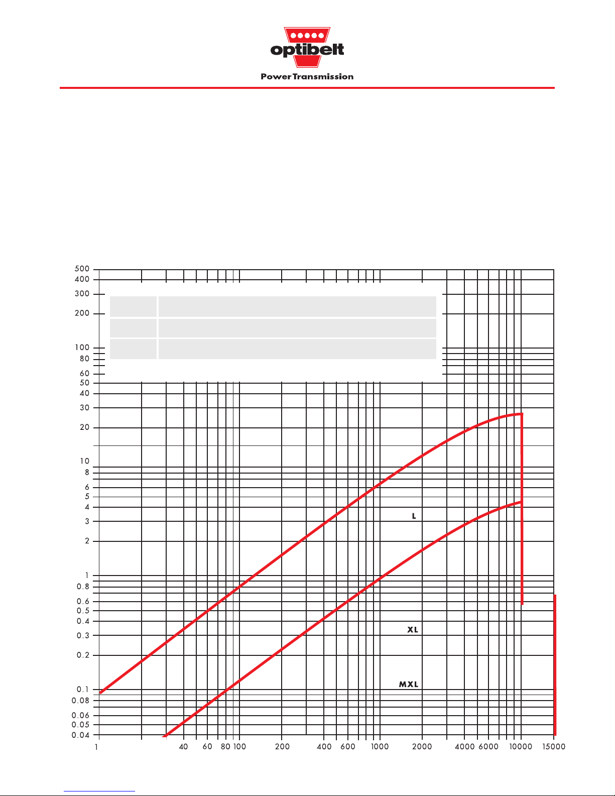
3.3 ZRM/ZRP belt selection graphs
Power rating graphs for section selection and maximum belt speeds for
optibelt
ZRM/ZRP timing belts, Z
emax
= 12
The maximum belt speeds for the individual timing belt sections in
these graphs are based on pulleys with 60 teeth, at least 12 of
which are in mesh. In addition each maximum width is based on
a combination of standard timing belts and standard pulleys (see
Table 3.4).
Wider belts can be used with special pulleys allowing increased
power transmission.
Specifying smaller pulley diameters, a smaller number of teeth in
mesh or narrower belts, will reduce the maximum power limits
proportionally.
Design power P
B
(kW) →
Speed of the small pulley nk (min
-1
) →
Graph 3.1: ZRP power ranges
Section
MXL* XL L T2.5 T5(D) T 10(D) T 20*(D)* AT 5* AT10* AT20*
bSt** (mm) 6.4 9.5 25.4 6 25 50 100 25 50 100
v
max
(m/s) 80 60 40 80 60 40 30 60 40 30
* Non stock
** Maximum width using a standard timing belt and a standard pulley
Table 3.4: Maximum standard width and speed
25
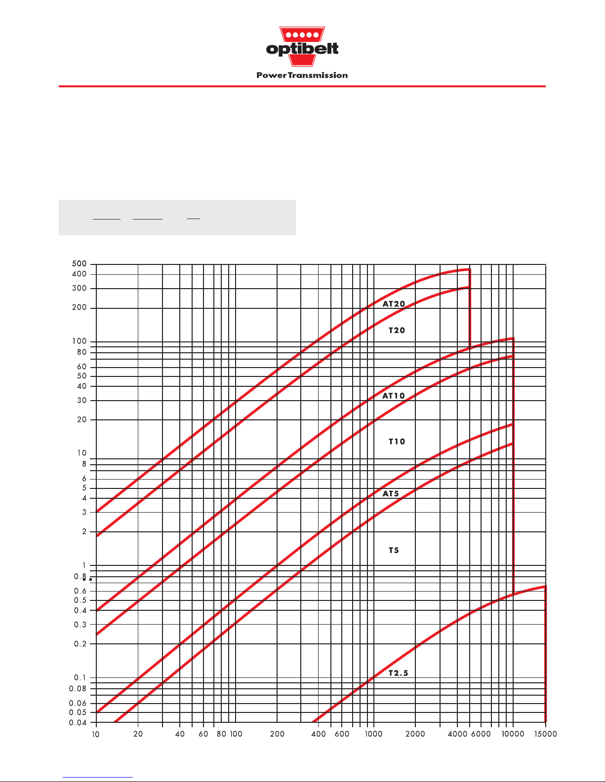
The belt speeds given in Table 3.4 should not be exceeded for the
standard drives. For belt speeds close to these maximum values,
increased belt tension is necessary.
3.3 ZRM/ZRP belt selection graphs
Power rating graphs for section selection and maximum belt speeds for
optibelt
ZRM/ZRP timing belts, Z
emax
= 12
The smaller of the two drive pulleys is used for the calculation
irrespective of whether it is used as a driver or a driven pulley.
The values given for the transmissible power P
spez
(W/cm) in Table
3.5, page 25 are based on one tooth in mesh, a 10 mm timing belt
width and one tooth of the small pulley.
These values are not based on the belt tension cord strength, but
on the shear strength of the teeth based on the particular mode of
operation.
Speed of the small pulley n
k
(min
-1
) →
Design power P
B
(kW) →
Graph 3.2: ZRM power ranges
v= =
dw1 · n
1
19100
dw2 · n
2
19100
( )
m
s

26
Prime mover
Prime mover: three-phase squirrel
cage electric motor
Power: PAn= 6.0 kW
Speed: n
1
= 1450 min
-1
Starting torque: MA= 2.0 M
N
Pulley clearance
diameter: as required
Drive width: b
1
, B␣ < 80 mm
Operating conditions
Daily operation: max. 16 hours
Starts/stops: approx.
150 per day
Ambient conditions: standard room
temperature, contact
with cutting oil
Drive centres: a = 410 ± 20 mm
Driven machine
Driven machine: drill
Absorbed power:PAb= 5.0 kW
Driven speed: n
2
= 600 ± 10 min
-1
Start condition: no load
Type of loading: intermittent operation with
average shock loading
Pulley clearance
diameter: < 300 mm
Width: b
1
, B as required
3.4 ZRM/ZRP drive design
Drive calculation for
optibelt
ZRM/ZRP timing belts, Z
emax
= 12
Formulae Calculation example
Design power and belt selection
Total service factor c
2
c2 = c0 + c6 + c
8
Basic service factor c0 Table 2.1, page 12
Pulley and idler factor c
6
Table 2.2, page 13
Start/stop factor c
8
Table 2.2, page 13
c2 = 1.8 + 0 + 0 = 1.8
c
0
= 1.8
c
6
= 0
c
8
= 0
Design power P
B
PB = PAb · c
2
PAb=
If P
Ab
unknown: PB= PAn · c2Formulae page 13
Select section from graph pages 24 and 25 using small pulley
speed n
k
PB = 5.0 · 1.8 = 9.0 kW
Section T10 nk = n1 = 1450 min
-1
Pulleys
For standard pulley ranges see pages 54 to 86,
For pulley materials and fitting see Table 5.3, page 44
T10 for standard pulleys see page 82
Number of teeth z1, z2, pitch diameter dw1, dw2 and
calculation of the drive ratio i
z
1
, dw1 see standard pulley range
z
2
= z1 · ii=
z
2
, dw2 see standard pulley range
Are clearance diameters and permissible sizes acceptable?
Clearance diameter including space to fit belt > da (resp. DB) + 2 · h
s
z1= 25 dw1= 79.58 mm see page 82
z
2
= 25 · 2.42 i = = 2.42
z
2
= 60 dw2= 190.98 mm see page 82
Bore: d
1
from 12 ... 30 mm d2 from 16 ... 60 mm
Clearance diam. >189.1 + 2 · 4.5 198.1 mm < 300 mm, hs see p. 5
1450
600
Driven speed n
2eff
and
drive ratio i eff
n
2eff
=i
eff
=
Pitch length and drive centres with allowances
Drive centres and pulley flange arrangements
0.5 · (D
Bk
+ dwg) + y < a < 2 · (dwg + dwk)
Flanges on small pulley, y
2k
see Table 5.1 page 43
0.5 · (83 + 190.98) + 10 = 147 mm 147 mm < a < 541 mm
L
wth
= 2 · 410 + · (190.98 + 79.58) +
L
wth
= 1252.6 mm
L
wSt
= 1250 mm for Section T10 see page 17
π
2
(dwg – dwk)
2
4 a
(190.98 – 79.58)
2
4 · 410
π
2
MAb · n
2
9550
n1 · z
1
z
2
n
2eff
= = 604 min-1i
eff
= = 2.4
z
2
z
1
n
1
n
2
60
25
1450 · 25
60
Theoretical and standard belt lengths L
wth
, L
wSt
*
L
wth
= 2 a + · (dwg + dwk) +
L
wSt
see standard belt range, pages 16 to 19

27
Formulae
Calculation example
Pitch length and drive centres with allowances
Nominal centres a
nom
a
nom
= K + K2 –
K= – (dwg + dwk)
a
nom
=
206.251 + 206.2512 – = 408.71 mm
K = – (190.98 + 79.58) = 206.251 mm
(dwg – dwk)
2
8
(190.98 – 79.58)
2
8
Centre distance allowances for installation and
tensioning a
nom
see Table 5.1, page 43;
installation: allowance y
tensioning: allowance x
y= y
1,2,3
depending on which pulleys are flanged
x
a
min
≤ a
nom
– y a
nom
+ x ≤ a
max
With fixed centres, a tension idler is necessary,
see page 45
Flanges on small pulley y
2k
= 10 mm
x ≥ 0,32 + 0.002 · 408.71 1.14 mmx ≥ 1.2 mm
a
min
≥ 398.7 409.9 mm ≤ a
max
L
wSt
4
1250
4
3.4 ZRM/ZRP drive design
Drive calculation for
optibelt
ZRM/ZRP timing belts, z
emax
= 12
* Please send for our special brochure: Centre distance values for Optibelt timing belts.
Order example
Timing belt and pulley designation
Quantity, type, width, section, pitch length
(special constructions or features if required)
1 Optibelt ZRM timing belt 50 T10/1250
1 Optibelt ZRS pulley 66 T10/25-2 Type 6F
1 Optibelt ZRS pulley 66 T10/60-0 Type 6
π
8
π
8
Values for F
v
, ev and Sa see page 28For calculation and setting of tension,
see page 28
→
Power P
spec
per tooth in mesh, 10 mm belt width
and one tooth of small pulley from Table 3.5, see
page 29
P
spez
(Profil, nk)P
spez
(T 10, 1450 min-1) = 6.850 W/cm
z
k
6
( )
dwg – d
wk
a
nom
25
6
Calculation for belt width bth, b
st
bth=c
3
from Table 2.3, page 13
Standard belt width b
St
page 16 to 19, bSt ≥ b
th
Drive width within specification?
Actual drive service factor c
2vorh
c
2vorh
= c
2
bth= = 47.8 mm c3 = 1.0
b
St
= 50 mm for section T10 see page 17
Total pulley width B = 66 mm, face width b
1
= 56 mm
c
2vorh
= 1.8 = 1.88
Calculation of
z
enom
, ze in mesh with small pulley,
z
emax
= 12, to be taken into account
z
enom
≥ z
emax
ze= z
emax
z
enom
< z
emax
ze= z
enom
z
enom
=3 –
11 < z
emax
ze = 11 z
enom
round off
z
enom
= 3 – = 11.4
Timing belt and pulley width
b
St
b
th
50
47.8
190.98 – 79.58
408.71
()
P
B
· 10000
P
spez
· c3 · zk · z
e
9.0 · 10000
6.850 · 1.0 · 25 · 11
→
→
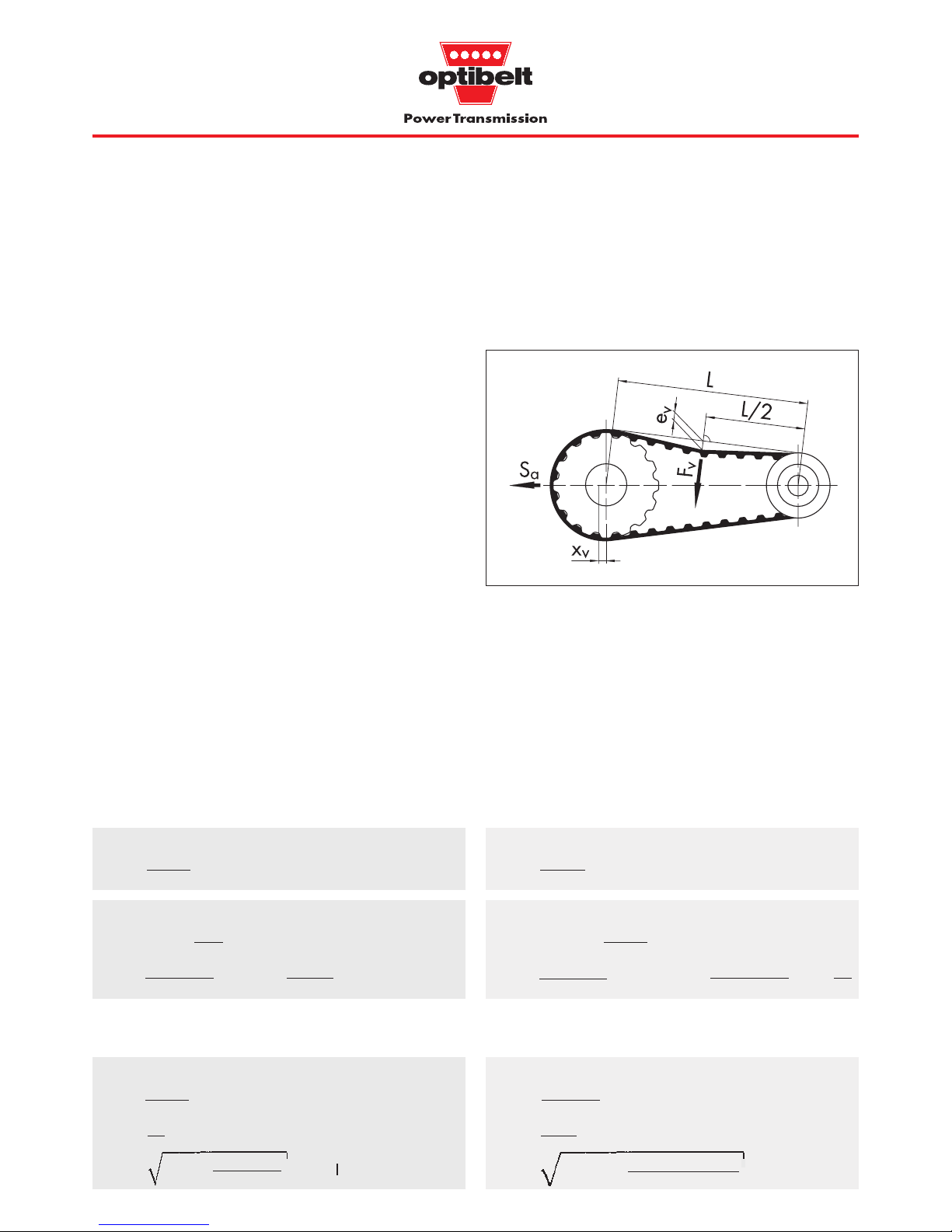
28
Correct tensioning is of special importance for the reliable and
efficient transmission of power. Proper tensioning of the stationary
belt will ensure that it will run at the correct tension.
● Insufficient tension coupled to high drive loads will lead to the
belt jumping teeth on the pulley and ultimately to belt breakage.
● Excessive tension under similar conditions will cause severe
wear, shearing of the belt teeth, excessive running noise and
bearing damage.
It is advisable therefore to calculate and set the static tension for
each drive individually using the formulae below. The tensioning
factor c
v
takes account of the loads combined in the overall service
factor c
2
.
Setting the static tension
One pulley only of the drive may be fixed when the static tension
is adjusted. The second pulley and the other pulleys of a multiple
pulley drive must be able to rotate freely.
The test force F
v
should be applied in the centre of the span length
‘L’ perpendicular to it. Sharp-edged objects MUST not be used for
depressing the timing belt to avoid belt kink. Correct static tension
is achieved when the deflection e
v
corresponds to the calculated
value.
When the drive system has more than the two pulleys shown in
Figure 3.1 the tension can be measured between any two pulleys
in the system provided the belt is in contact with these pulleys with
the same face (top or bottom). The only difference will be ev which
will change as a function of span length.
3.5 ZRM/ZRP tensioning
Calculation and setting of tension for
optibelt
ZRM/ZRP timing belt drives
Alternatively, the belt can be tensioned statically using the calculated static shaft load S
a
.
By virtue of the zero stretch tension cord, the belt will require no
further tension checks after fitting.
Tensioning
Test force Fv and deflection ev for span length L
F
v
=c
v
and Sn3 see above
e
v
=L = a
nom
for i U 1
L= a
nom
2
– for i U 1
Fv= = 54 N
e
v
= = 8.0 mm
L = 408.71
2
– = 401.05 mm
L
50
(dwg – dwk)
2
2
1.3 · 828
20
401.1
50
(190.98 – 79.58)
2
2
Static shaft load Sa and centrifugal force S
n3
Sa= cv · S
n3
L see below
S
n3
=v
eff
= formulae page 13
L
a
nom
Sa= 1.3 · 828 = 1056 N
S
n3
= = 828 N v
eff
= = 6.04
5.0 · 1000
6.04
401.05
408.71
Tension factor and forces
Tension factor c
v
cv= + 0.9 1.05 ≤ c
v
cv= + 0.9 = 1.3
1.8 – 1
2
Formulae
Example (using the values from page 27)
79.58 · 1450
19100
m
s
For formula symbols, see also page 14
F
v
= load to set tension (N)
S
n3
= centrifugal force (N)
e
v
= span deflection under load F
v
(mm)
L = span length (mm)
dw1 · n
1
19100
PAb · 1000
v
eff
c2 – 1
2
cv · S
n3
20
Figure 3.1: Adjusting belt tension
•
•
•
•
•
•
••
•
•
•
•
•
•
•

29
0.037
0.074
0.110
0.146
0.181
0.351
0.509
0.658
0.728
0.797
0.928
1.052
1.076
1.169
1.281
1.336
1.389
1.493
1.594
1.694
1.793
1.843
1.893
1.993
2.095
2.201
2.310
2.424
2.580
2.768
2.949
3.124
3.167
3.293
3.457
3.614
3.767
3.914
4.057
4.195
4.330
4.460
4.586
4.710
5.005
5.284
5.553
5.815
6.074
6.334
6.601
6.877
7.167
7.475
0.006
0.012
0.017
0.023
0.029
0.057
0.083
0.109
0.122
0.134
0.158
0.181
0.185
0.203
0.224
0.235
0.245
0.265
0.284
0.303
0.321
0.329
0.338
0.355
0.372
0.388
0.403
0.419
0.449
0.478
0.507
0.535
0.542
0.564
0.593
0.623
0.654
0.683
0.710
0.735
0.761
0.785
0.809
0.832
0.886
0.937
0.984
1.027
1.068
1.106
1.141
1.174
1.205
1.235
1.291
1.345
1.399
1.455
1.516
0.101
0.201
0.300
0.397
0.493
0.953
1.382
1.782
1.972
2.156
2.505
2.832
2.895
3.139
3.428
3.567
3.702
3.962
4.211
4.451
4.685
4.800
4.914
5.141
5.367
5.596
5.829
6.068
6.550
6.999
7.428
7.837
7.936
8.226
8.597
8.950
9.287
9.607
9.912
10.203
10.480
10.745
10.997
11.238
11.796
12.301
12.766
13.203
13.625
14.044
14.472
14.922
15.407
15.939
0.006
0.012
0.017
0.023
0.029
0.057
0.083
0.109
0.122
0.134
0.158
0.181
0.185
0.203
0.224
0.235
0.245
0.265
0.284
0.303
0.321
0.329
0.338
0.355
0.372
0.388
0.403
0.419
0.449
0.478
0.507
0.535
0.542
0.564
0.593
0.623
0.654
0.683
0.710
0.735
0.761
0.785
0.809
0.832
0.886
0.937
0.984
1.027
1.068
1.106
1.141
1.174
1.205
1.235
1.291
1.345
1.399
1.455
1.516
0.035
0.069
0.103
0.137
0.170
0.331
0.484
0.629
0.698
0.766
0.897
1.022
1.046
1.140
1.253
1.307
1.361
1.464
1.563
1.659
1.751
1.796
1.841
1.928
2.014
2.098
2.193
2.290
2.479
2.661
2.838
3.008
3.050
3.173
3.332
3.486
3.635
3.780
3.920
4.055
4.186
4.314
4.438
4.558
4.846
5.118
5.377
5.627
5.872
6.114
6.359
6.608
6.867
7.137
0.137
0.273
0.407
0.539
0.670
1.302
1.899
2.462
2.731
2.993
3.495
3.970
4.061
4.418
4.844
5.048
5.247
5.631
5.998
6.349
6.686
6.850
7.012
7.328
7.636
7.939
8.239
8.537
9.136
9.806
10.396
10.957
11.093
11.489
11.994
12.473
12.927
13.357
13.764
14.150
14.516
14.862
15.190
15.502
16.214
16.845
17.414
17.938
18.436
18.924
19.423
19.948
20.519
21.153
0.561
1.113
1.656
2.191
2.718
5.230
7.551
9.693
10.701
11.670
13.497
15.186
15.509
16.752
18.208
18.899
19.568
20.845
22.054
23.207
24.503
25.130
25.743
26.927
28.056
29.134
30.162
31.142
32.969
34.633
36.150
37.539
37.868
38.817
40.001
41.110
42.160
43.170
44.157
45.139
46.133
47.157
48.228
49.364
0.055
0.109
0.162
0.215
0.268
0.524
0.768
1.002
1.114
1.224
1.437
1.641
1.681
1.836
2.023
2.113
2.202
2.374
2.540
2.700
2.855
2.931
3.005
3.151
3.293
3.433
3.570
3.705
3.972
4.239
4.511
4.759
4.821
5.004
5.239
5.464
5.680
5.886
6.084
6.273
6.454
6.628
6.795
6.955
7.328
7.669
7.983
8.277
8.558
8.832
9.104
9.383
9.674
9.983
0.221
0.440
0.656
0.870
1.081
2.101
3.064
3.972
4.407
4.829
5.637
6.400
6.547
7.120
7.802
8.128
8.447
9.058
9.640
10.194
10.725
10.982
11.234
11.726
12.202
12.667
13.123
13.573
14.468
15.440
16.319
17.146
17.344
17.921
18.647
19.325
19.958
20.547
21.095
21.604
22.075
22.510
22.912
23.282
24.082
24.728
25.251
25.682
26.051
26.389
26.728
27.098
27.530
28.056
0.858
1.705
2.539
3.361
4.172
8.052
11.655
14.995
16.572
18.088
20.948
23.590
24.094
26.029
28.280
29.340
30.358
32.277
34.052
35.699
37.231
37.960
38.858
40.469
41.979
43.392
44.713
45.944
48.155
50.057
51.679
53.053
53.362
54.211
55.181
55.997
56.688
57.285
57.820
58.323
58.825
59.356
59.949
60.633
20
40
60
80
100
200
300
400
450
500
600
700
720
800
900
950
1000
1100
1200
1300
1400
1450
1500
1600
1700
1800
1900
2000
2200
2400
2600
2800
2850
3000
3200
3400
3600
3800
4000
4200
4400
4600
4800
5000
5500
6000
6500
7000
7500
8000
8500
9000
9500
10000
11000
12000
13000
14000
15000
3.6 ZRM/ZRP power rating table
Power ratings for
optibelt
ZRM/ZRP timing belts z
emax
= 12
Speed
of small pulley
nk (min-1)
P
spez
(W/cm)
Table 3.5: ZRM/ZRP power ratings*
* For notes on Table 3.5, see page 25. P
spez
per tooth in mesh, 10 mm belt width and one tooth of small pulley.
MXL XL L T2.5 T5(D) T10(D) T20(D) AT5 AT10 AT20
 Loading...