

Optibelt OPTIKRIK 0, OPTIKRIK III, OPTIKRIK II, OPTIKRIK I Instruction Manual
OPTIKRIK
TENSION GAUGES
FOR OPTIBELT V-BELTS AND
RIBBED BELTS
This simplied method for static tension measuring should be used
for installation and maintenance tensioning of the belt when the
important technical data is unavailable and the optimum tension
cannot be calculated. This method requires only knowledge of the
small pulley diameter and the belt section and construction. The
gauges may also be used to set tensions when the optimum tension
has been calculated from known technical data.
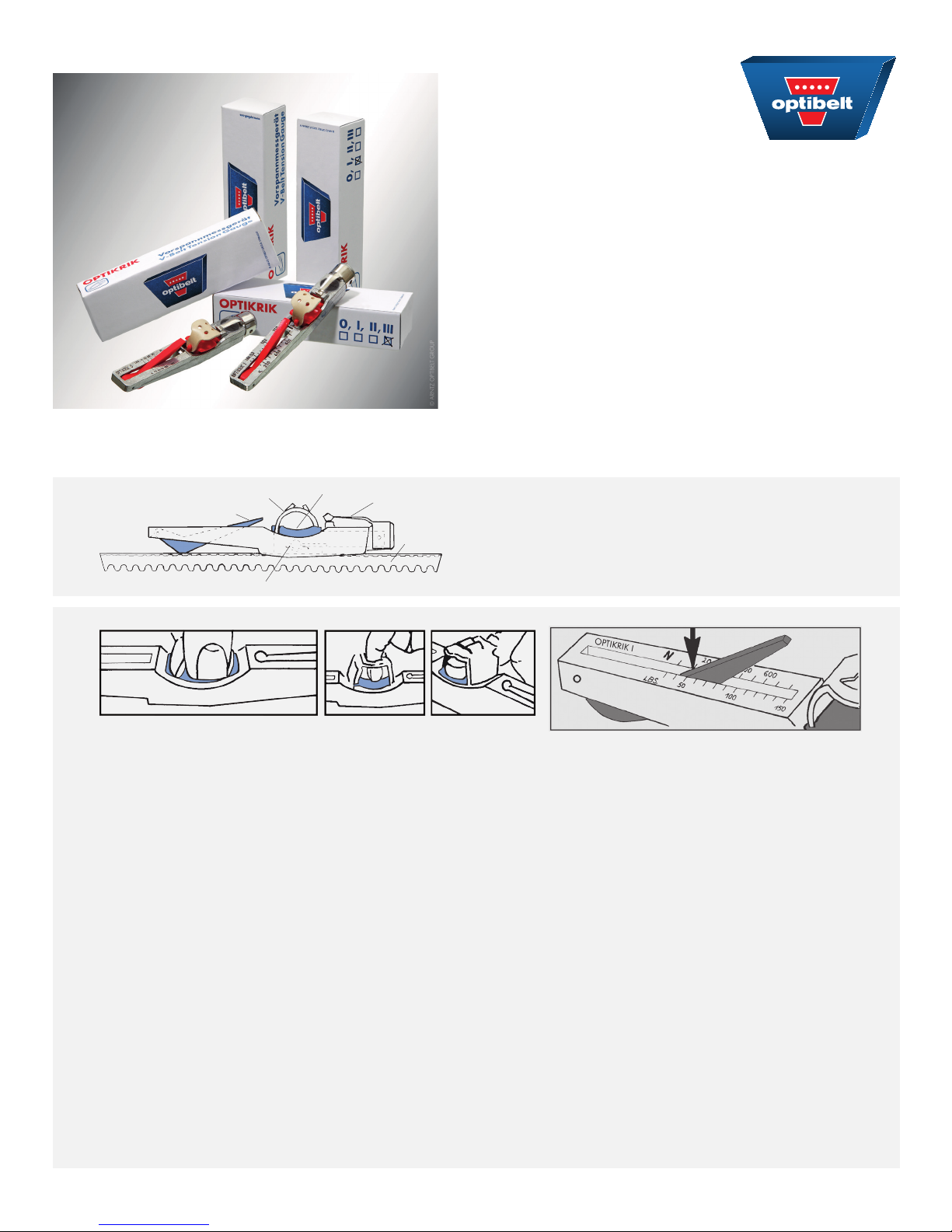
OPTIBELT TENSION GAUGES – INSTRUCTIONS FOR USE –
rubber nger loop
indicator arm
pressure spring
A B C
1. Select the gauge appropriate to the belt section and construction being tensioned. See notes below the simplied
tensioning table.
2. The illustration above (A, B or C) shows three ways to hold the gauge so that pressure is applied to the pad only.
3. Position the gauge on one of the belts on the drive in the middle of an accessible span length. Take care to ensure that
the gauge is only in contact with one of the belts, and that the indicator arm is pushed down into the gauge body.
Align the gauge so that its body is parallel with the sides of the belt.
4. Push down on the pressure pad slowly and rmly with one nger in one of the ways illustrated above (A, B or C).
When a “click” is heard and / or felt, stop immediately and remove the gauge carefully to avoid disturbing the indicator
arm.
pressure pad
pocket clip
V-belt
Tension Gauges:
OPTIKRIK 0 Range: 15 - 35 Lbs. / 70 - 150 N
OPTIKRIK I Range: 30 - 150 Lbs. / 150 - 600 N
OPTIKRIK II Range: 100 - 300 Lbs. / 500 - 1400 N
OPTIKRIK III Range: 300 - 700 Lbs. / 1300 - 3100 N
5. Read the gauge to judge the tension as follows and as illustrated in the sketch above.
6. Turn the gauge sideways to ascertain the exact point where the top surface of the indicator arm crosses the scale.
7. Mark this point mentally or with a thumbnail and turn the gauge to read the scale.
8. Check the tension found against the simplied tensioning table or the calculated tension.
Tighten or slacken the belt, if necessary.
© ARNTZ OPTIBELT GROUP
888-529-8844 WWW.OPTIBELT.CA

V-BELTS
Diameter
Belt
section
A/AX
13/X13
4L
Z/ZX
10/X10
3L
B/BX
17/X17
5L
C/CX
22/X22
3V/3VX
9N/9NX
SPZ/XPZ
SPA /XPA
5V/5VX
15N/15NX
SPB/XPB
SPC/XPC
8V
* Tension values for these pulleys and belt types must be calculated, please consult an OPTIBELT representative.
of the small
pulley
[in]
≤ 3.15
> 3.15 ≤ 4.12
> 4.12 ≤ 5.20
> 5.20*
≤ 2.20
> 2.20 ≤ 2.80
> 2.80 ≤ 3.95
> 3.95*
≤ 4.90
> 4.90 ≤ 6.30
> 6.30 ≤ 8.00
> 8.00*
≤ 8.00
> 8.00 ≤ 9.75
> 9.75 ≤ 14.0
> 14.0*
≤ 2.80
> 2.80 ≤ 3.65
> 3.65 ≤ 5.00
> 5.00*
≤ 3.95
> 3.95 ≤ 5.50
> 5.50 ≤ 8.00
> 8.00*
≤ 6.30
> 6.30 ≤ 9.00
> 9.00 ≤ 14.0
> 14.0*
≤ 9.75
> 9.75 ≤ 14.0
> 14.0 ≤ 21.2
> 21.2*
Standard
(wrapped)
Initial
installation
35
45
70
90
120
140
70
90
110
160
180
200
45
55
80
80
90
110
150
160
200
220
310
400
After
30-120 min.
operation
25
35
55
70
90
110
55
70
90
110
140
160
35
45
55
55
70
90
110
120
160
180
250
310
SUPER X-POWER
Initial
installation
45
55
90
120
140
160
100
110
135
180
200
220
55
70
90
90
110
135
160
190
220
310
360
450
Check of the belt tension with help of the length addition value
TENSION VALUES MEASURED IN: LBS.
RED POWER 3
SUPER TX
After
30-120 min.
operation
35
45
70
90
110
130
80
90
100
140
160
180
45
55
70
70
90
100
120
150
180
250
270
350
HVAC POWER
Initial
installation
new belts
45
55
90
— — — — —
100
110
135
— — — — —
55
70
90
90
110
135
160
190
220
310
360
450
New
installation
existing belts
35
45
70
80
90
100
45
55
70
70
90
100
120
150
180
250
270
350
BLUE POWER
Diameter
of the small
pulley [in]
— — —
— — —
— — —
— — —
≤ 7.00
> 7.00 ≤ 9.30
> 9.30 ≤ 15.8
> 15.8*
≤ 11.0
> 11.0 ≤ 14.7
> 14.7 ≤ 27.5
> 27.5*
Initial
installation
new belts
175
275
375
350
560
700
After
30-120 min.
operation
150
200
275
275
425
550
AUTOMOTIVE BELTS
Belt section Initial installation
AVX 10, MARATHON 1 & 2 550 ± 50 350 ± 50 ≥ 200
AVX 13, MARATHON 1 & 2 650 ± 50 400 ± 50 ≥ 300
KB - 2 AVX 10 1100 ± 50 700 ± 50 ≥ 400
KB - 3 AVX 10 1650 ± 50 1050 ± 50 ≥ 600
KB - 2 AVX 13 1300 ± 50 800 ± 50 ≥ 600
KB - 3 AVX 13 1950 ± 50 1200 ± 50 ≥ 900
RB - 3 PK 400 ± 50 250 ± 50 ≥ 200
RB - 4 PK 500 ± 50 350 ± 50 ≥ 250
RB - 5 PK 600 ± 50 400 ± 50 ≥ 300
RB - 6 PK 750 ± 50 500 ± 50 ≥ 350
RIBBED BELTS
Belt
section
PH
PJ
PK
PL
Diameter of the
small pulley
db [mm]
≤ 25
> 25 ≤ 71
> 71 *
≤ 40
> 40 ≤ 80
> 80 ≤ 132
> 132 *
≤ 63
> 63 ≤ 100
> 100 ≤ 140
> 140 *
≤ 90
> 90 ≤ 140
> 140 ≤ 200
> 200 *
Initial
installation
90
110
200
200
250
300
400
450
800
1000
1100
After
30-120 min.
operation
4 PH 8 PH 12 PH 16 PH 20 PH
70
90
4 PJ 8 PJ 12 PJ 16 PJ 24 PJ
150
150
200
4 PK 8 PK 10 PK 12 PK 16 PK
250
300
350
6 PL 8 PL 10 PL 12 PL 16 PL
600
700
800
installation
TENSION VALUES MEASURED IN: NEWTONS [N]
After 30-120 min. operation
Initial
150
200
350
400
450
600
800
900
1000
1300
1400
STATIC TENSION T
After
30-120 min.
operation
130
150
300
350
350
450
600
700
800
1000
1100
Initial
installation
250
300
500
600
700
700
1000
1100
1300
1600
1900
NEWTONS [N]
MAX
After
30-120 min.
operation
200
250
400
500
550
600
700
800
1000
1300
1400
Initial
installation
300
350
700
800
900
900
1200
1300
1500
1900
2100
Minimum tension
Operating
after
run-in
250
300
550
650
700
700
900
1000
1200
1500
1600
Initial
installation
400
450
1000
1200
1300
1200
1500
1600
1900
2500
2800
After
30-120 min.
operation
300
350
800
1000
1000
900
1200
1300
1500
1900
2100
 Loading...