

Optibase MGW 2400 WMT User Manual
MGW 2400
WMT Streaming Server
User's Manual

Trademarks
Optibase and MGW are trademarks of Optibase Inc.
Microsoft, MS, and MS-DOS, Windows, Windows NT, Windows 2000,
Windows XP, Windows Media Player, Windows Media Server (WMS) and
Windows Media Services are trademarks of Microsoft Corporation.
Java is a registered trademark from Sun Microsystems.
IBM PC, XT, AT are registered trademarks of International Business Machine
Corporation.
All other trademarks mentioned in this manual are the sole property of their
respective manufacturers.
Copyright
Optibase Inc., California. (c) 2003 Optibase Inc. All rights reserved.
Published 2003, Israel
MPEG-4 Packaged Media Notice
Any use of this product other than consumer personal use in any manner that
complies with the MPEG-4 standard for encoding video information for
packaged media is expressively prohibited without a license under applicable
patents in the MPEG-4 Patent portfolio. The required license is available from
MPEG LA, L.L.C., 250 Steele Street, Suite 300, Denver Colorado 80206.
Notice
Information in this document is subject to change without notice. Optibase
Inc. and Optibase Ltd. assume no responsibility for any errors that may appear
in this manual. Companies, names and data used in examples herein are
fictitious unless otherwise noted. No part of this document may be copied or
reproduced in any form, or by any means, electronic or mechanical, for any
purpose, without the express written permission of Optibase Inc. Optibase
makes no warranties with respect to this documentation and disclaims any
implied warranties of merchantability or fitness for a particular purpose. From
time to time changes may occur in the file names and in the files actually
included on the distribution disks. Optibase makes no warranties that such
files or facilities, as mentioned in this documentation, exist on the distribution
disks or as part of the materials distributed.

Safety Instructions
Use the following safety guidelines to help protect your MGW
2400 unit from potential damage and to ensure your own
personal safety.
When using MGW 2400
As you operate MGW 2400, observe the following safety
guidelines
Note
Do not open the MGW 2400 unit, as this will void your warranty. MGW 2400
does not contain any user serviceable parts.
• Before installing MGW 2400, unplug the system to help
prevent electric shock or system board damage. Certain
system board components continue to receive power any
time MGW 2400 is connected to AC power.
• To help prevent electric shock, plug the power cable into
properly grounded sources. Use only properly grounded
extensions and adaptors as the need arises.
• Use only a UL Recognized power cord.
• Make sure nothing rests on your MGW 2400 power cable
and that the cables are not located where they can be
stepped or tripped over.
• Do not spill food or liquids on your MGW 2400 unit.
• Do not push any objects into free slots of your MGW 2400
unit. Doing so will damage your MGW 2400 unit and can
cause fire or electrical shock by shorting out interior
components.

• Keep your MGW 2400 unit away from radiators and heat
sources. Also, do not block cooling vents. Avoid placing
loose papers underneath your MGW 2400 unit. Do not
place your MGW 2400 unit in a closed-in wall unit or on a
bed, sofa, or rug.
• When you disconnect a cable, pull on its connector or on its
strain relief loop, not on the cable itself. Some cables have a
connector with locking tabs; if you are disconnecting this
type of cable, press in on the locking tabs before
disconnecting the cable. As you pull connectors apart, keep
them evenly aligned to avoid bending any connector pins.
Also, before you connect a cable, make sure both
connectors are correctly oriented and aligned.
• ESD Warning: Normal handling precautions should be
taken to avoid static discharge.

Compliance Information
FCC User Information
This equipment has been tested and found to comply with the limits for a
Class A digital device, pursuant to Part 15 of the FCC Rules. These limits are
designed to provide reasonable protection against harmful interference when
the equipment is operated in a commercial environment. This equipment
generates, uses and can radiate radio frequency energy and, if not installed and
used in accordance to the instruction manual, may cause harmful interference
to radio communication. Operation of this equipment in a residential area is
likely to cause harmful interference in which case the user will be required to
correct the interference at his own expense.
NOTE: This product was FCC verified under test conditions that included the
use of shielded I/O cables and connectors between system components. To be
in compliance with FCC regulations, the user must use shielded cables and
connectors and install them properly.
Canadian Interference Statement
This Class A digital apparatus complies with Canadian ICES-003.

Declaration of Conformity
Manufacturer’s Name: Optibase Ltd.
Manufacturer’s Address: 7 Shenkar St., Herzliya 46120, Israel
Description of Equipment: MGW 2400 WMT Streaming Server with MGE-400D and
MGE-400 Encoders
Date of Issue: 2002
Directive Complied With: 89/336/EEC, 73/23/EEC, 93/68/EEC
Harmonized Standards to which Conformity is Declared:
• EN 60950 Safety
• EN 61000-3-2 Harmonic Current Emission
• EN 61000-3-3 Flickermeter
• EN 55022:1987 Class A Conducted and Radiated Emission
• Immunity EN55024
• EN 61000-4-2 ESD Contact/Air Discharge 4kV/8kV
• EN 61000-4-3 Radiated Immunity 10V/m (27-1000Mhz, AM 1KHz 80%)
• EN 61000-4-4 EFT&B 1kV 5/50nS, 5KHz rep.
• EN61000-4-5 Surge Withstand (2kV common and 1kV differential mode
on AC line)
• EN 61000-4-6 Current Injection Immunity 3 vrms
• EN61000-4-8: Power Magnetic field (1 A/m 50Hz)
• EN 61000-4-11 Voltage Dips Immunity
We, the undersigned hereby declare that the equipment specified above conforms to
the above Directive and Standards.
Manufacturer:
Full Name: Itzhak Keren
Place: Israel
Signature
Position: Director Quality & Engineering
Date 11/7/02

Content
Introduction ............................................................ 1
Overview .................................................................. 1
System Description .................................................. 2
System Overview.....................................................2
MGW 2400 Features ...............................................3
What’s in this Manual............................................... 4
Configuration & Installation .................................. 5
Overview .................................................................. 5
System Configuration............................................... 6
MGW 2400 Components .........................................6
Peripheral Components...........................................8
Getting Started......................................................... 9
Unpacking MGW 2400 ..........................................10
Power Supply ........................................................11
Servicing MGW 2400.............................................11
Hardware Overview ...............................................12
Connecting Peripherals - Encoders & Sources .....16

Initial Configuration ................................................ 20
Configuring HyperTerminal....................................20
DHCP enabled Networks.......................................22
Changing Passwords.............................................27
MGW 2400’s Network Settings..............................28
If DHCP is disabled – TCP/IP Settings..................34
MGW 2400 Utilities................................................39
Working with SCSI Disks.......................................41
Uploading Files......................................................44
Changing Settings from a Remote PC ................... 45
Operating MGW 2400 ........................................... 47
Overview ................................................................ 47
Installing Software.................................................. 48
System Requirements ...........................................48
Configuring the Management PC for the Network.48
Installing the MGW 2400 EMS...............................49
Installing Microsoft Components............................52
Accessing MGW 2400............................................ 53
User Profiles ..........................................................54
Logging on to MGW 2400......................................55
Viewing and Editing the List of Permitted Users....57
Viewing the List of Users Currently Logged On.....58
Logging off MGW 2400..........................................58

Main Window Overview.......................................... 59
The Modules Page ................................................60
The Channels Page...............................................61
The Platform Page.................................................62
Toolbar and Displays.............................................66
Viewing and Setting Module Parameters ............... 67
I/O Parameters ......................................................67
Encoding Parameters ............................................70
Tools......................................................................71
Editing the Channel Profile..................................... 72
Adding a Channel ..................................................73
Editing an existing Channel ...................................75
Removing Channels ..............................................75
Viewing the Channel Profile ..................................76
Managing Templates .............................................77
Managing Configurations.......................................79
Editing Channel Parameters .................................. 81
Encoding Parameters ............................................81
Adjusting Video Parameters On The Fly ...............85
Target Parameters.................................................86
Operating Channels ............................................... 91
Receiving and Playing Back Streams....................92
Upgrading MGW 2400 ........................................... 94

Technical Specifications ..................................... 97
Chassis .................................................................. 97
Physical .................................................................97
Electrical Characteristics .......................................97
Input/Output Interfaces ..........................................98
Environmental........................................................98
Safety Standards ...................................................98
Management..........................................................99
Network Protocols .................................................99
Encoding Modules ............................................... 100
Physical Dimensions ...........................................100
Standard Compliance ..........................................100
Input Signals........................................................100
Encoding Format .................................................100
Video Resolutions and Bit-Rates.........................101
Audio Modes and Bit-Rates.................................101
System Defaults................................................... 103
My System Settings ............................................. 103
User Names and Passwords................................ 104
MGW 2400 EMS Users .......................................104
MGW 2400 Administrator ....................................104
Troubleshooting................................................. 105
Hardware Errors................................................... 105
Errors while running MGW 2400 EMS ................. 108
Error Messages.................................................... 110

Chapter 1
Introduction
Overview
MGW 2400 is a multi-channel WMT encoding and streaming
server designed to enable the deployment of advanced streaming
media services over the broadband Internet and corporate
networks.
MGW 2400 encodes and streams up to six live Microsoft WMT
compliant streams over broadband terrestrial and wireless
networks such as xDSL, FTTx, satellite, cable, Ethernet LANs
and the Internet. It supports live WMT stream upload to
Microsoft Windows Media Server and IP multicast, unicast, UDP
and HTTP protocols, ensuring efficient transmission over a wide
range of networks. MGW 2400 encodes up to six live channels
concurrently at bit-rates between 64 kbps and 2 Mbps.
In this Chapter
• System Description, page 2
• What’s in this Manual, page 4
Chapter 1 • System Description
System Description
System Overview
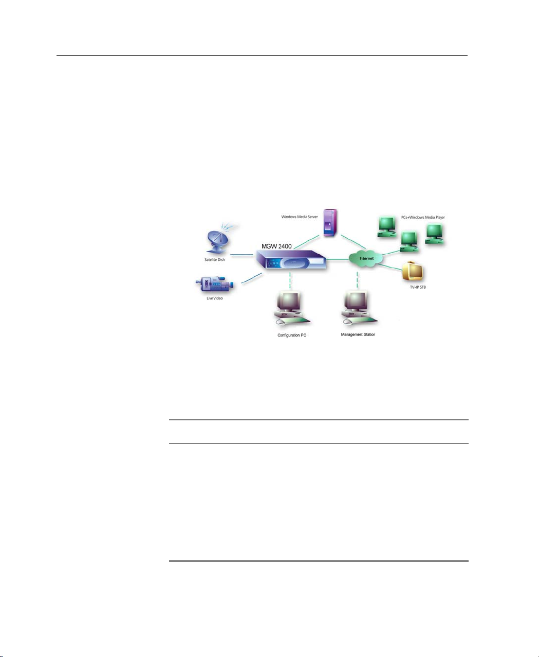
MGW 2400 easily integrates with networking equipment and
complementary video equipment. This section describes MGW
2400 and its features.
2
Figure 1: MGW 2400 in a Network
Table 1 lists the PCs needed to configure and operate MGW
2400.
Computer Task
Configuration PC Connected
via RS-232
Management Station PC in the
network
Receiving Client PC in the
network
Table 1: Computers serving and controlling MGW 2400
Initializes and reconfigures MGW
2400 using HyperTerminal.
Reconfigures MGW 2400 using
Telnet and operates it from MGW
2400 EMS.
The Management Station is referred
to as Management PC or Remote
PC.
Receives and plays back video and
audio using Windows Media Player.

Chapter 1 • System Description
MGW 2400 Features
• Multi-channel rack-mount video streaming server.
• Encodes, multiplexes and transmits up to 6 live Microsoft
WMT compliant streams.
• Real-time uploading to a Windows Media Server.
• Multiple multicast targets and on-demand live unicast
targets per channel.
• Saves encoded streams to file.
• SNMP management application.
• Bit-rate adjustment on the fly.
• Network traffic shaping (smoothing).
3

Chapter 1 • What’s in this Manual
What’s in this Manual
This manual shows you how to use MGW 2400 as follows:
• Chapter 1 presents an overview of MGW 2400.
• Chapter 2 shows you how to install and configure MGW
• Chapter 3 shows you how to install software and operate
• Chapter 4 provides you with MGW 2400's technical
• Chapter 5 provides you with a troubleshooting guide.
2400.
MGW 2400.
specifications.
4

Configuration & Installation
Overview
MGW 2400 is a rack-mountable stand-alone server. Up to six
WMT encoding modules can be installed in MGW 2400's
chassis.
You may operate MGW 2400 from any PC on your network
that has the MGW 2400 EMS installed.
In this Chapter
• System Configuration, page 6
• Getting Started, page 9
• Initial Configuration, page 20
• Changing Settings from a remote PC, page 45
Chapter 2

Chapter 2 • System Configuration
System Configuration
This section lists the MGW 2400 components. It also explains
and describes optional and required peripheral components,
which are not supplied by Optibase.
MGW 2400 Components
The following components are supplied by Optibase, if not
otherwise noted.
Component Description
MGW 2400 chassis 'Housing' of the MGW 2400 system.
Power cord that fits your local
Din socket.
Network cables - shielded
category 5
19", 23" or ETSI mounted
bracket
RS-232 cable Connects PC to MGW 2400.
SCSI disk Connects to MGW 2400 and stores video
Connects to MGW 2400's power connector
(not supplied by Optibase).
Connect MGW 2400's NIC A and B to two
different network segments
(not supplied by Optibase).
Rack-mounts MGW 2400.
clips
(not supplied by Optibase).
Table 2: Chassis
6

Chapter 2 • System Configuration
Component Description
MGE-400 encoding module Module for WMT encoding from analog
sources.
MGE-400D encoding module Module for WMT encoding from analog or
digital sources.
Video BNC cable Connects a Composite Video source to
MGW 2400.
Low Loss Digital Video Belden
Connects an SDI source to MGW 2400.
1694A cable
S-Video MiniDIN cable Connects an S-Video source to MGW
2400.
Audio Stereo MiniJack cable Connects an analog audio source to
MGW 2400.
RCA Coaxial cable Connects a digital audio source to MGW
2400.
Table 3: Encoding Modules
Component Description
MGW 2400 Configuration Utility Pre-installed software to configure MGW
MGW 2400 EMS SNMP based Transmission management
2400.
software that you install on a PC on the
network. This PC is referred to as
Management PC.
Table 4: Software
Document Description
MGW 2400 User’s Manual Shows you how to install and operate
MGW 2400.
MGW 2400 EMS Help Shows you how to use the MGW 2400
EMS. It installs together with the MGW
2400 EMS on the Management PC.
Table 5: Documentation
7

Chapter 2 • System Configuration
Peripheral Components
This section lists peripheral components that serve MGW 2400.
Optibase does not supply these components.
Hardware Description
PC (Windows 2000 or XP) with
available COM1 port. This PC will
be referred to as Configuration PC.
Management PC
(Windows 2000 or XP).
Connects to MGW 2400 via RS-232 to
initialize and configure.
Reconfigures MGW 2400 using Telnet
and operates it from MGW 2400 EMS.
The Management Station is referred to
as Management PC or Remote PC.
Software Description
External Windows Media Server. Installed on a PC on the network,
Windows Media Services 4.1. Installed on a PC on the network,
Windows Media Player 9 Series. Installed on a PC on the network,
Table 6: Peripherals
broadcasts WMT streams received from
MGW 2400.
manages and operates the Windows
Media Server.
receives and plays WMT streams.
Note
Depending on available resources, you may use the same PC for MGW
2400's peripheral software components.
8

Chapter 2 • Getting Started
Getting Started
This section describes how to unpack and start working with
MGW 2400.
• To unpack and rack-mount MGW 2400, refer to page 10
• For a hardware overview, refer to page 12.
• For instructions on installing and removing encoding
modules and connect sources, refer to page 16.
• For instructions on initializing MGW 2400, refer to page
20.
• For instructions on configuring MGW 2400 for the
network, refer to page 28.
• For instructions on configuring MGW 2400's network
parameter settings if your network's DHCP is disabled, refer
to page 34.
• For instructions on sharing a SCSI disk's drive with the
network, refer to page 41.
• For instructions on configuring MGW 2400 by using
Telnet, refer to page 45.
9

Chapter 2 • Getting Started
Unpacking MGW 2400
Mounting MGW 2400 into a Rack
1. Choose a dry location for MGW 2400, which complies
with the requirements regarding temperature specified at
page 98.
2. Attach the rubber feet to MGW 2400 or rack-mount it into
a rack-mount chassis. To rack-mount MGW 2400, refer to
the following section.
MGW 2400 can be used as a stand-alone device or rackmounted into a 19”, 23” or ETSI rack-mount chassis. To rackmount MGW 2400, do the following:
1. Remove the rubber feet from the bottom, if they have been
already attached.
2. Use the supplied screws to attach the brackets to the
corners of the MGW 2400 chassis.
10
3. Attach MGW 2400 to the rack-mount chassis.
Note
Disconnect the power cable from the power connector while mounting MGW
2400.

Chapter 2 • Getting Started
Power Supply
MGW 2400 works with 90/260V AC. The power cord connects
to the power connector on MGW 2400’s rear panel. MGW 2400
recognizes your local voltage automatically.
MGW 2400 does not ship with a power cord. You will have to
purchase a power cord that fits your local DIN socket.
Servicing MGW 2400
MGW 2400 does not require any maintenance. If MGW 2400 is
in need of repair, you have to call for technical support. MGW
2400 does not contain parts, which you may service or repair by
yourself. Opening MGW 2400 will void your warranty.
To clean MGW 2400:
Clean MGW 2400 with a soft and dry rag only and do not open
the unit.
Note
Before performing any task on the MGW 2400 unit, switch MGW 2400 off
and disconnect the power cable to avoid accidents and electrical hazards.
11
Chapter 2 • Getting Started
A
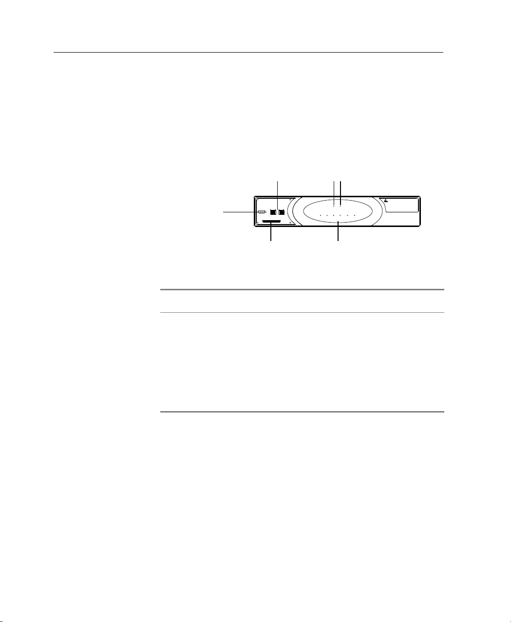
Hardware Overview
Front Panel
The following section provides you with a quick overview of
MGW 2400's hardware.
Power LED
ALARM POWER
1
23
4
56
Channels
6 Channel LEDs
optibase
MGW 2400
RS-232 Port
RJ-45 Ethernet Links
10 / 100 Base T10 / 100 Base T
RS-232
SCSI Port
larm LED
B
A
SCSI
Figure 2: MGW 2400 Front Panel
Ports Description
RS-232 Connects the Configuration PC to MGW
RJ-45 Ethernet Link A and B Connects MGW 2400 to the network.
SCSI Ultrawide II Connects MGW 2400 to a basic type
Table 7: MGW 2400 Front Panel
2400.
A connects NIC A
B connects NIC B.
SCSI disk. MGW 2400 does not
recognize SCSI disks with management
applications installed on them.
12

LEDs Description
Chapter 2 • Getting Started
Power Off
Blinks green
Green
Alarm Off
On
Ethernet Link Off
Orange
Ethernet Transmit Off
Flashes green
(Channel) 1-6 Off Empty slot
Blinks red
(if module inserted)
Slot error (software not loaded)
Green Encoding module inserted and
Blinks green Encoding
Red Encoding module inserted,
Certain errors may cause this
Table 8: MGW 2400 Front Panel LEDs
No power
Booting
Power on
No error
At least one fan is running too
slowly or failed.
No connection
Connected
No transmission
Transmitting
MGW 2400 is booting.
ready to encode.
channel error.
LED to flash.
Note
To avoid damaging MGW 2400’s hardware, turn MGW 2400 off immediately
once the Alarm LED turns red.
13
Chapter 2 • Getting Started
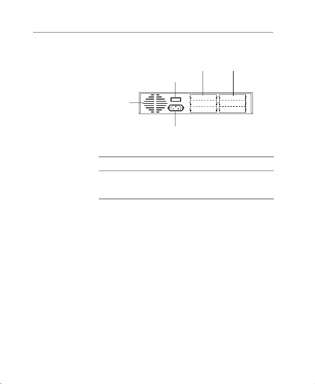
Rear Panel
Fan
Power Switch
0
I
Slots for six Encoding Modules
Power Connector
Figure 3: MGW 2400 Rear Panel
Ports Description
Six slots Install up to six encoding modules.
Power connector Connects the power cord.
Power switch Switches MGW 2400 on and off.
Table 9: MGW 2400 Rear Panel
14
Chapter 2 • Getting Started
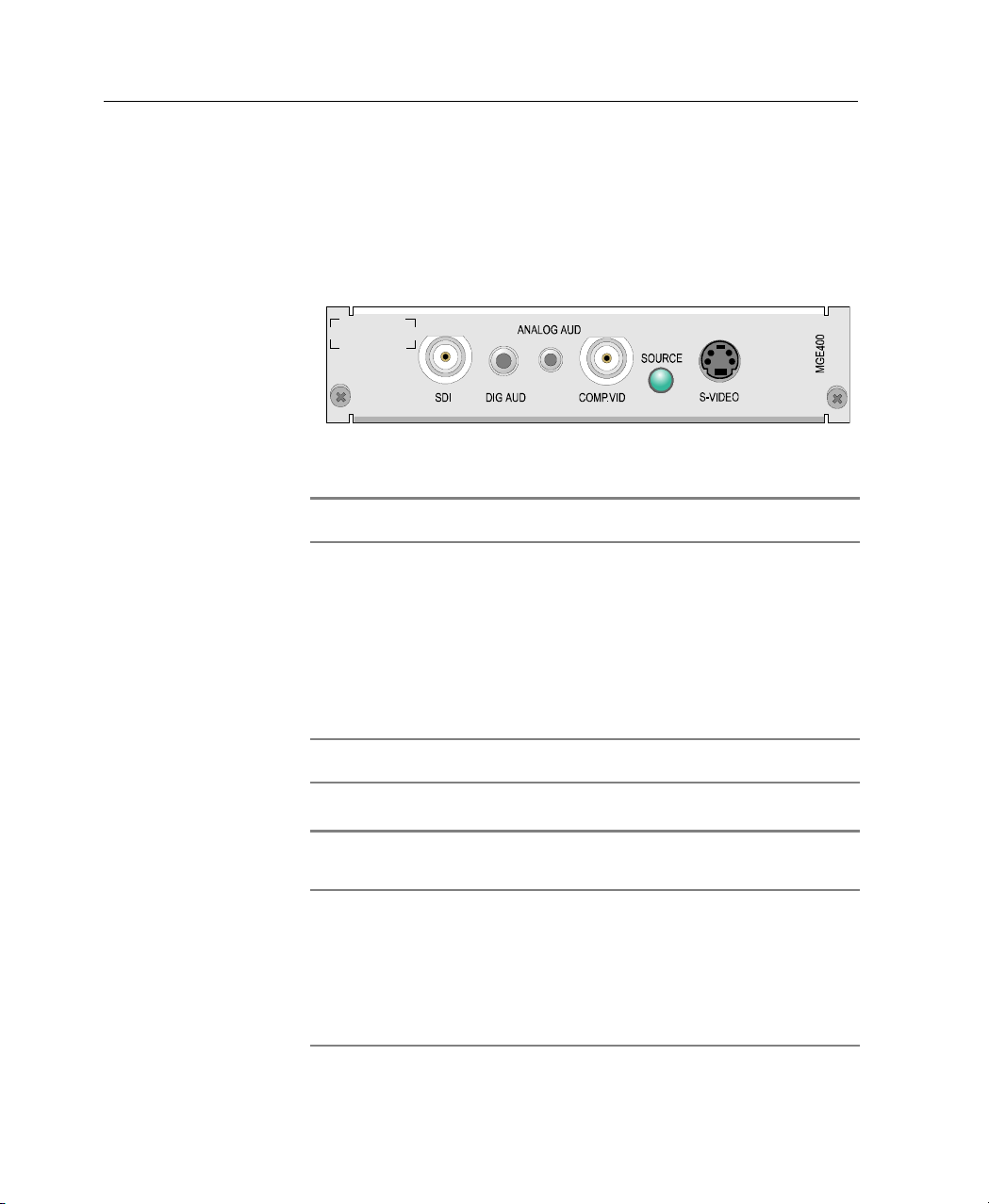
Encoding Module
MGW 2400 supports MGE-400 and MGE-400D encoding
modules. MGE-400 encoding modules support analog sources
while MGE-400D encoding modules support both analog and
digital sources.
Figure 4: MGE-400D Encoding Module Interface
Connectors Description
ANALOG AUD Connects analog audio source to MGW 2400.
DIG AUD Connects a digital audio source to MGW 2400. This
connector is only used for MGE-400D modules.
COMP.VID Connects a Composite video source to MGW 2400.
S-VIDEO Connects an S-Video Source to MGW 2400.
SDI Connects a digital video source to MGW 2400. This
connector ships only with MGE-400D encoding
modules.
LEDs Description
Source Off
Green
Table 10: MGE-400 and 400D Encoding Module Interfaces
Bad or no video source.
Video source detected.
Note
MGE 400D encoding modules support the SMPTE 125M-1995 SDI standard.
Other SDI standards will cause the video frames to be shifted 10 lines down.
I.e. the content of the top 10 video lines is unknown and the 10 bottom lines
will not be encoded.
15

Chapter 2 • Getting Started
Connecting Peripherals - Encoders & Sources
To install an encoding module:
1. Make sure that MGW 2400 is switched off and disconnect
the power cable.
2. Remove the slot cover of the free slot in which you want to
install an encoding module.
3. Firmly push the encoding module into the slot until you
hear a click. This may require some force. A correctly
inserted module should be completely flush with the rest of
the unit, and must not protrude at all from the slot.
4. Screw the module to MGW 2400's rear panel.
5. Connect video and audio sources to the encoding module
as explained at page 18.
6. Switch MGW 2400 on again.
7. To add a new channel and set channel parameters, refer to
page 73.
16
Note
• Do not install or remove encoding modules while running MGW 2400.
This will cause damage to your MGW 2400 chassis and encoding
modules.
• Avoid touching inside free slots as this may cause electrical hazards
and damage your MGW 2400 unit.
• The Source LED only turns green if a video source is connected to the
encoding module. If you only connect an audio source, the Source LED
remains off.

Chapter 2 • Getting Started
To remove an encoding module:
1. Make sure that MGW 2400 is switched off and disconnect
the power cable.
2. Disconnect video and audio source cables.
3. Loosen the screws on the left and right side of the rear
panel and carefully pull the encoding module out of the
slot.
4. Screw the slot cover to MGW 2400’s rear panel.
5. Switch MGW 2400 on again.
Note
• Do not install or remove encoding modules while running MGW 2400.
This will cause damage to your MGW 2400 chassis and encoding
modules.
• Avoid touching inside free slots as this may cause electrical hazards.
Touching inside free slots may also damage your MGW 2400 unit.
17
Chapter 2 • Getting Started
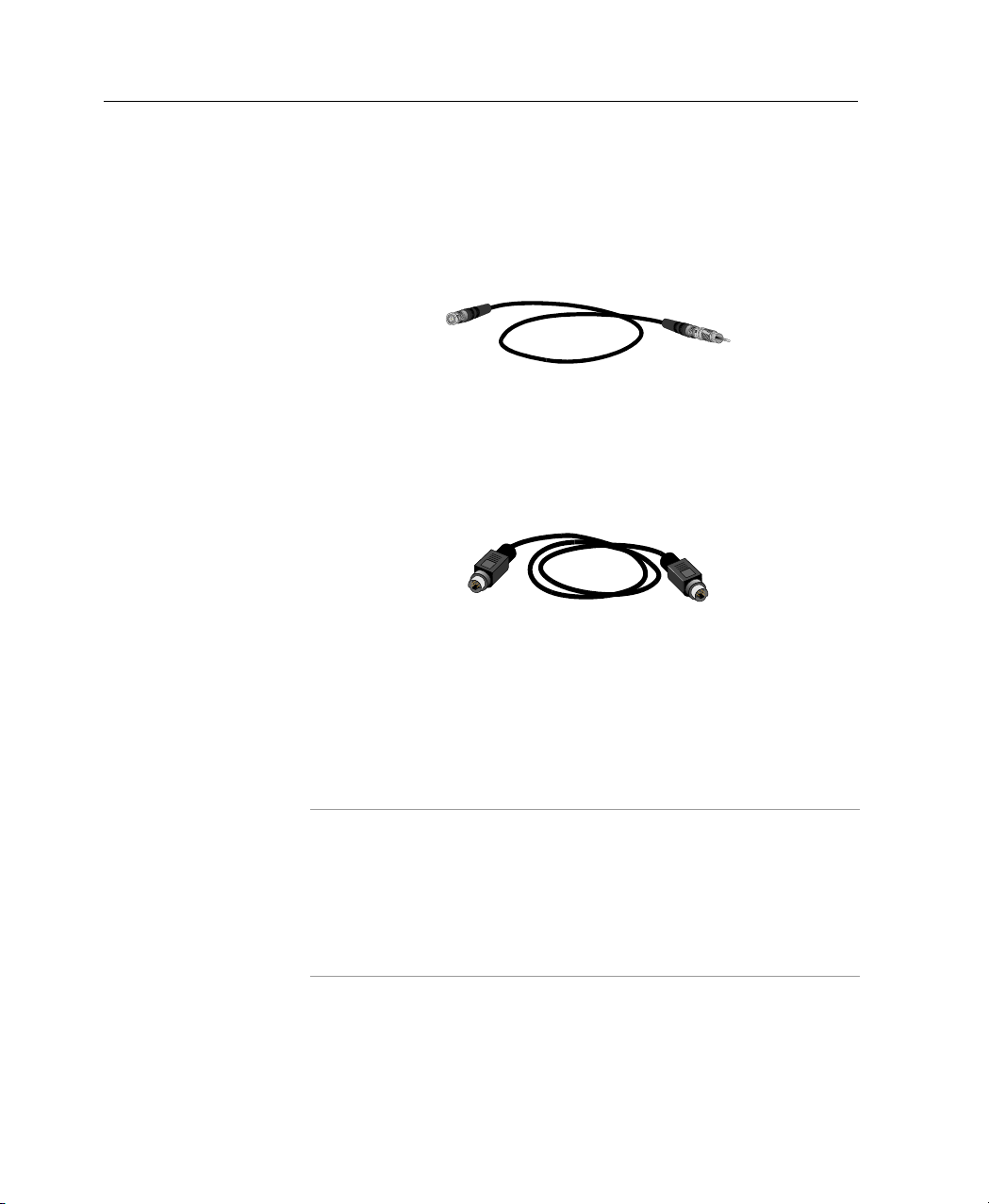
To connect a video source
• Composite Video. Use the Video BNC cable (catalog
number BZA3636) as illustrated in Figure 5 to connect a
Composite video source to the COMP.VID connector.
Figure 5: The Video BNC Cable (BZA3636)
• S-Video. Use the S-Video MiniDIN cable (catalog number
WCA2210) as illustrated in Figure 6 to connect an S-Video
source to the S-Video connector.
Figure 6: The S-Video MiniDIN Cable (WCA2210)
18
• Digital Video. Use the Low Loss Digital Video Belden
1694A cable (catalog number WCA5971) to connect a
digital video source to the SDI connector. This connector
ships with MGE-400D encoding modules only.
Note
• MGE 400D encoding modules support the SMPTE 125M-1995 SDI
standard. Other SDI standards will cause the video frames to be shifted
10 lines down. I.e. the content of the top 10 video lines is unknown and
the 10 bottom lines will not be encoded.
• MGW 2400 does not support SECAM sources.
Chapter 2 • Getting Started
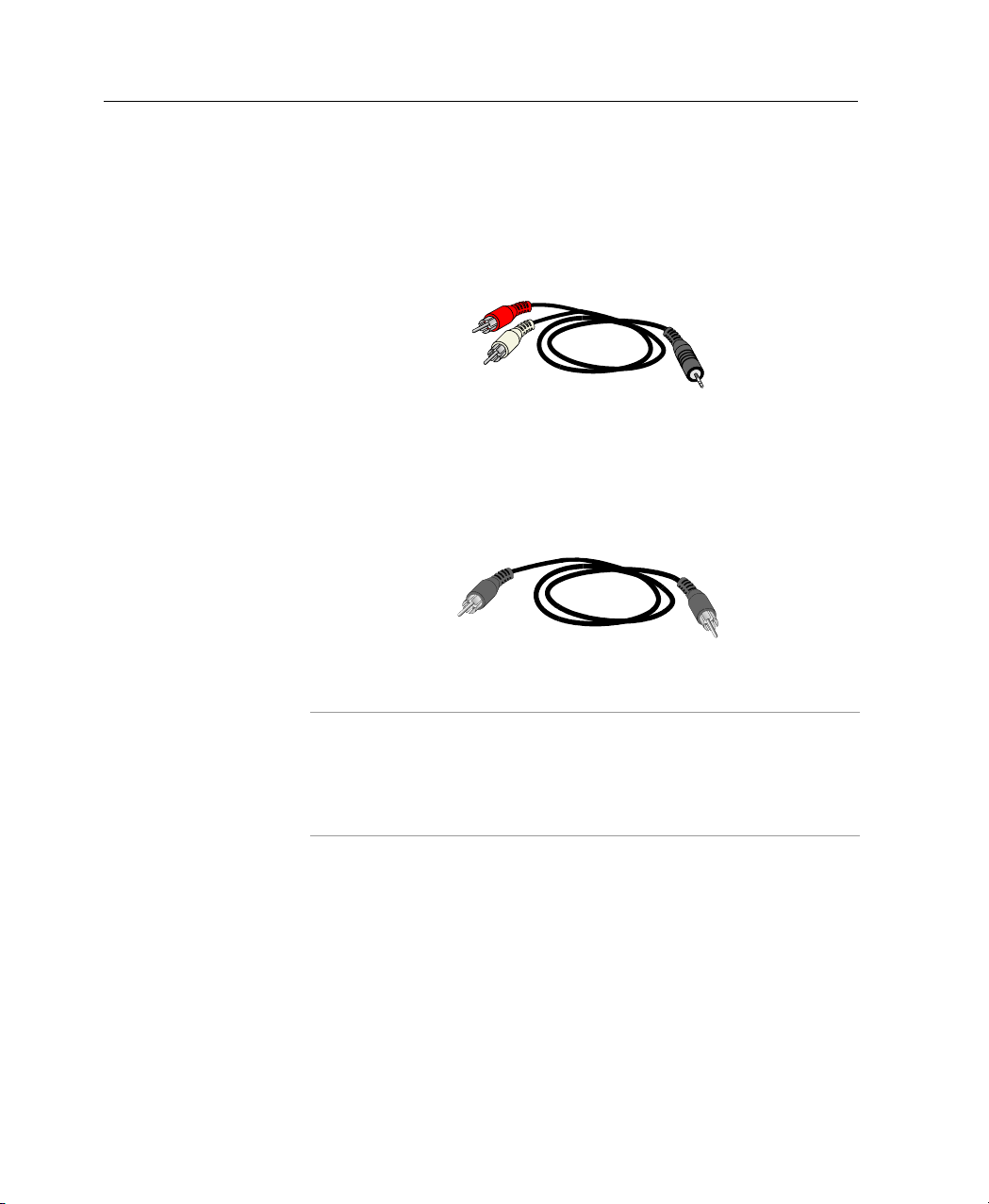
To connect an audio source:
• Analog audio. Use the Stereo MiniJack audio cable
(catalog number WCA2274) as illustrated in Figure 7 to
connect the audio source to the ANALOG AUD connector.
Figure 7: The Stereo MiniJack Audio Cable (WCA2274)
• Digital audio. Use the RCA Coaxial cable (catalog number
WCA2199) as illustrated in Figure 8 to connect the audio
source to the DIG AUD connector.
Figure 8: The RCA Coaxial Cable (WCA2199)
Note
• You can connect digital audio sources to MGE-400D encoding modules
only.
• MGW 2400 does not support SECAM sources.
19

Chapter 2 • Initial Configuration
Initial Configuration
Configuring HyperTerminal
To operate MGW 2400 for the first time, you use
HyperTerminal to log on to MGW 2400's Configuration Utility.
To log on to MGW 2400's Configuration Utility you use the
user name Administrator. The default password for this user is
Administrator.
HyperTerminal is pre-installed on PCs that run on Windows
NT, 2000 or XP. For further information on HyperTerminal,
refer to the Microsoft Windows documentation.
Optibase has provided you with pre-configured HyperTerminal
settings, which are available on MGW 2400's CD. To apply
these settings, do the following:
1. Use a serial cable to connect MGW 2400’s RS-232 port to
the Configuration PC's serial COM1 port.
20
2. Switch MGW 2400 on and wait until it finishes booting,
which is the case once the Power LED turns green. You
cannot apply the HyperTerminal settings before.
3. On MGW 2400's CD, go to HyperTerminal Settings and
copy MGW2400.ht to your Communication PC.
4. Right-click MGW2400.ht, choose Properties and clear
Read-Only.
5. Double-click MGW2400.ht; HyperTerminal appears and
you can log on to MGW 2400's Configuration Utility.
If you do not have the CD available, you have to manually
configure HyperTerminal for first use.
 Loading...