

FF 30 - FF 100
Wall mounted, balanced flue, fanned gas boiler
User Instructions
Manufactured exclusively for Plumb Center by Ideal Boilers
Optia

Optia FF
(Natural Gas Models Only)
Optia FF 30 ....... G.C. No. 41 391 54
Optia FF 40 ....... G.C. No. 41 391 95
Optia FF 50 ....... G.C. No. 41 391 96
Optia FF 60 ....... G.C. No. 41 391 97
Optia FF 70 ....... G.C. No. 41 391 98
Optia FF 80 ....... G.C. No. 41 391 99
Optia FF 100 ..... G.C. No. 41 392 01
Introduction
It is essential that the instructions in this booklet are
strictly followed, for safe and economic operation of
the boiler.
Current Gas Safety (Installation &
Use) Regulations or rules in force.
In your own interest, and that of safety, it is the law that this
boiler must be installed by a CORGI registered installer or in IE
a competent person, in accordance with the above regulations.
Electricity Supply
This appliance must be efficiently earthed.
Supply: 230 V ~ 50 Hz.
The fusing should be 3A.
Connection must be made in a way that allows complete
isolation of the electrical supply such as a double pole switch
having a 3mm (1/8") contact separation in both poles, or a
plug and socket, serving only the boiler and system controls.
The means of isolation must be accessible to the user after
installation.
Important notes
a. This appliance must not be operated without the casing
correctly fitted and forming an adequate seal.
b. If the boiler is installed in a compartment then the compartment
MUST NOT be used for storage purposes.
c. The ventilation provided for the boiler during installation MUST
NOT be blocked, and a check should be made periodically
that the ventilation areas are free from any obstruction.
Minimum clearances
A clearance of 533mm (21") MUST be available at the front of the
boiler for servicing.
The minimum clearances given below MUST be complied with
in order to maintain the safe running of the boiler .
Above the boiler 100 mm (4")
At each side of the boiler 5 mm (
Underneath the boiler 100 mm (4")
In front of the boiler 75 mm (3")
1/4")
To light the boiler. Refer to Frame 1
If a programmer is fitted, refer to separate instructions for the
programmer before continuing.
1. CHECK THAT THE ELECTRICITY SUPPLY TO THE BOILER
IS OFF.
2. Open the controls access door by hinging downwards.
3. Ensure that the gas inlet cock (D) is OPEN.
4. Press the overheat reset button (E), located as shown in
Frame 1.
5. Ensure that the mains on/off switch (C) is in the OFF
position.
6. Switch ON the electricity supply to the boiler. Check that all
external controls, e.g. room thermostat etc., are ON.
7. Turn the boiler thermostat knob (B) to position 6 and the
mains on/off switch (C) to ON. After about 15 seconds the
boiler will light automatically - this can be viewed through
the sight glass (A).
Set the boiler thermostat to the desired position.
8. Close the controls access door.
In winter conditions, i.e. central heating and domestic hot
water, the thermostat should be set at position 5 or 6.
For summer conditions, i.e. domestic hot water only, the
thermostat should be set at position 3.
These settings, however, are offered for general guidance only
and other settings may be found preferable, dependent upon
the type of system installed or as recommended by the
installer.
Control of water temperature
1. Adjust the boiler thermostat (B) to give the required
temperature of central heating.
2. The boiler thermostat automatically switches the main
burner OFF and ON to maintain the selected temperature.
Approximate flow temperatures for the boiler thermostat
settings are:
d. If it is known or suspected that a fault exists on the boiler then
it MUST NOT be used until the fault has been corrected by a
CORGI registered installer or in IE a competent person.
e. Where the boiler is fitted with a Vertex flue system with a
draught diverter in the loft the loft space MUST NOT be used
as a dwelling area.
f. Under NO circumstances should any of the sealed
components on this appliance be used incorrectly or tampered
with.
CAUTION. To avoid the possibility of injury during the installation, servicing or cleaning of
this appliance care should be taken when handling edges of sheet steel components
2
Knob Setting Flow Temperature
°C °F
1 56 133
2 61 142
3 66 152
4 72 161
5 77 170
6 82 180
Optia FF - Users

1
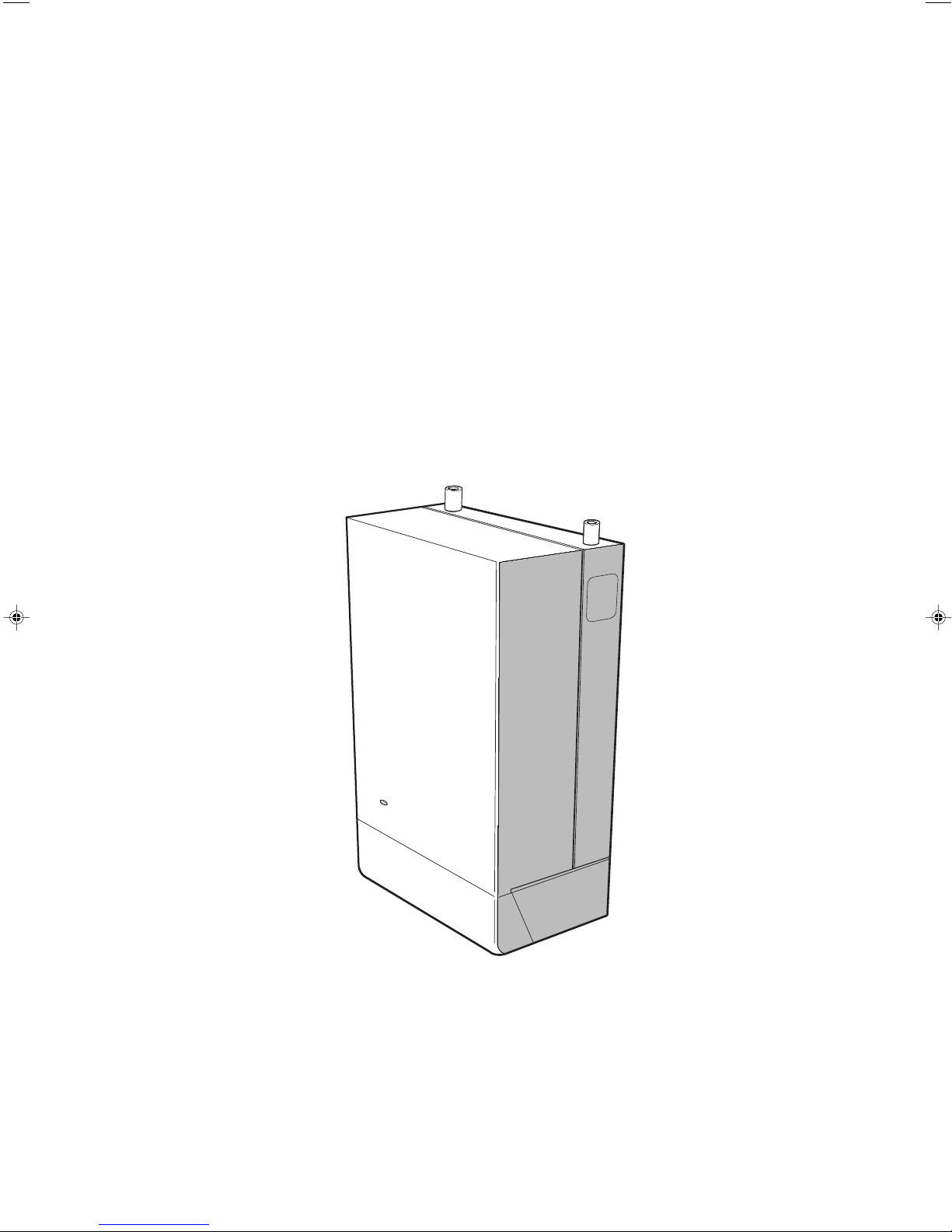
BOILER CONTROLS
View inside boiler controls area
LEGEND
A Sightglass.
B Thermostat knob.
C Mains on/off switch.
D Gas service cock (shown in the OPEN position).
E Overheat thermostat reset button.
To shut down the boiler
1. For short periods
Turn the boiler on/off switch (C) to OFF.
When heating is again required, restore the switch to ON.
2. For longer periods
Turn the boiler ON/OFF switch (C) to OFF.
Switch the electricity supply to OFF.
To relight the boiler
Repeat the procedure 1 - 8, detailed in 'To light the boiler'.
Frost protection
If no frost protection is provided and frost is likely during a short
absence from home, leave the heating controls at a reduced
temperature setting.
For longer periods, the entire system should be drained including the domestic water supply. If the system includes a
frost thermostat then, during cold weather, the boiler should be
turned OFF at the time switch(es) ONLY. The mains supply
should be left switched ON, with the boiler thermostat left in the
normal running position.
Boiler Overheat Thermostat
The boiler is fitted with a safety 'cutout' thermostat. This will shut
down the boiler in the event of overheating. Should this occur
allow the boiler to cool, press the reset button (E) then relight as
detailed in steps 1-8 in 'To light the boiler'.
If the cutout condition still persists turn off the boiler and consult
a CORGI registered installer or in IE a competent person.
Loss of system water pressure
Boilers fitted with Optia Sealed System Units only
If the red arrow on the unit pressure gauge is set above zero
and the system pressure is seen to fall below this value over
a period of time then a water leak is indicated. In this event a
CORGI registered installer or in IE a competent person
should be consulted.
DO NOT OPERATE THE BOILER IF THE PRESSURE HAS
REDUCED TO ZERO FROM THE ORIGINAL SETTING.
Escape of gas
Should a gas leak be suspected, contact your local gas
supplier without delay.
Do NOT search for gas leaks with a naked
flame.
Cleaning
For normal cleaning simply dust with a dry cloth.
To remove stubborn marks and stains, wipe with a damp
cloth and finish off with a dry cloth.
Do NOT use abrasive cleaning materials.
Maintenance
The appliance should be serviced at least once a year by a
CORGI registered installer or in IE a competent person.
All CORGI registered installers carry a CORGI ID card, and have a registration number. Both should be recorded in
the Benchmark Commissioning Checklist. You can check your installer by calling CORGI direct on 01256 372300.
Caradon Ideal Limited is a member of the Benchmark initiative and fully supports the aims of
the programme. Benchmark has been introduced to improve the standards of installation and
commissioning of central heating systems in the UK and to encourage the regular servicing of
all central heating systems to ensure safety and efficiency.
THE BENCHMARK SERVICE INTERVAL RECORD MUST BE COMPLETED AFTER EACH SERVICE
Optia FF - Users
3

POINTS FOR THE BOILER USER
Note. In line with our current warranty policy we would ask that you check through the following guide to identify any
problems external to the boiler prior to requesting a service engineers visit. Should the problem be found to be other than
with the appliance we reserve the right to levy a charge for the visit, or for any pre-arranged visit where access is not gained
by the engineer.
TROUBLESHOOTING - TYPICAL NON PRODUCT FAULTS
Problem Solution
Boiler is not working for
central heating or hot water.
If the boiler is fitted with a
sealed system kit.
Boiler goes through the
ignition sequence but will not
fire for central heating or hot
water.
Boiler is operating
satisfactorily for domestic hot
water but will not operate for
central heating.
Boiler is operating
satisfactorily for central
heating but will not operate
for domestic hot water.
Boiler will not fire the pilot
light is lit but the igniter
continues to spark and the
main burner does not ignite.
Boiler cycling on and off the
fan and burner come on for
short periods but the pump
can be heard.
• Check on/off switch ( C ) is in the ‘on’ position.
• Press overheat thermostat (E) - the boiler should then relight – If the fault recurs turn off the
boiler and contact the installer.
• Check pressure gauge on the boiler this should read a minimum of 1 bar If below 1 bar repressurise the system via the filling loop. Once pressure reaches 1 bar turn off the tap on the
filling loop and press the overheat thermostat reset button (E) to reset the boiler. If unable to
do so or if the pressure continues to drop after refilling contact your installer.
• Check gas supply (try at another gas appliance e.g. cooker / fire) – If no gas supply then not a
boiler fault – contact your gas supplier.
• If an external programmer is fitted check that the central heating channel is at an ‘on’ period.
• Check that the room thermostat is set at the required temperature. Test the room thermostat
by turning this fully up – if this does not respond contact your installer.
• If an external programmer is fitted check that the domestic hot water channel is at an ‘on’
period.
• Check that the domestic hot water cylinder thermostat is set at the required temperature. Test
the cylinder thermostat by turning this fully up – if this does not respond contact your installer.
• This is a symptom of crossed polarity i.e. the live and neutral supply to the boiler are crossed
over. This is not a boiler fault contact your installer to correct the wiring.
• There is an air lock in the boiler or system popework and the interrupter thermostat is shutting
down the boiler. Vent air from the radiators and ensure all thermostatic radiator valves are in
the open position. If unable to free the air lock contact your installer.
The code of practice for the installation,
commissioning & servicing of central heating systems
Optia Consumer Helpline: 0870 8498057
April 2005 UIN 200 777 A03
 Loading...