

Page 1
●Specifications of Measuring Range
①
CD33-30N(P) CD33-50N(P) CD33-85N(P) CD33-120N(P) C D33-250N(P)
②
CD33-30N(P)A CD33-50N(P)A CD33-85N(P)A CD33-120N(P)A CD33-250N(P)A
③
CD33-30N(P)V CD33-50N(P)V CD33-85N(P)V CD33-120N(P)V CD33-250N(P)V
④
CD33-30N(P)-422 CD33-50N(P)-422 CD33-85N(P)-422 CD33-120N(P)-422 CD33-250N(P)-422
①
CD33-30CN(P) CD33-50CN(P) CD33-85C N(P) CD33-120CN(P) CD33-250CN(P)
②
CD33-30CN(P)A CD33-50CN(P)A CD33-85CN(P)A CD33-120C N(P)A CD33-250CN(P)A
③
CD33-30CN(P)V CD33-50CN(P)V CD33-85CN(P)V CD33-120C N(P)V CD33-250CN(P)V
④
CD33-30CN(P)-422 CD33-50CN(P)-422 CD33-85CN(P)-422 CD33-120CN(P)-422
CD33-250CN(P)
30mm 50mm 85mm 120mm 250mm
±4mm ±10mm ±20mm ±60mm ±150mm
0.15×0.15mm 0.6×1.2mm 0.9×1.5mm 1.2×1.8mm 1.5×2.5mm ③Function indicator lights up.
0.1×0.1mm 0.5×1.0mm 0.75×1.25mm 1.0×1.5mm 1.75×3.5mm
0.15×0.15mm 0.4×0.9mm 0.6×1.0mm 0.5×0.8mm 2.0×4.5mm
7.5ms max.
18ms max.
54ms max. ④Select function by pressing Select button.
●Specifications of Output
Dual output Analogue Voltage RS422 ①Press simultaneously both the Select button and Set button for 5 seconds.
CD33- ① CD33- ② CD33- ③ CD33- ④
RS422
Type
Cable type
Connector type
Center
Measuring range
Light source Red laser Diode (wave length 655nm)
Peak power Max. output 1mW
Laser Class
IEC/JIS CLASS2
FDA CLASSⅡ
Spot size
(approx.
volume)
*1
Near
Middle
Far
Linearity *2
Sampling period
±0.1% F.S.
(F.S.=8mm)
±0.1% F.S.
(F.S.=20mm)
±0.1% F.S.
(F.S.=40mm)
±0.1% F.S.
(F.S.=120mm)
±0.3% F.S.
(F.S.=300mm)
Resolution *3
2μm
(Fast:4μm)
5μm
(Fast:8μm)
10μm
(Fast:15μm)
30μm
(Fast:45μm)
75μm
(Fast:150μm)
Response
time
Fast averaging: 1 time 5ms max.
Standard averaging: 16 times 12.5ms max.
High resolution averaging: 64 times 36.5ms max.
500 ,750(250mm type) /1000 /1500 /2000μs
Temperature Drift ±0.08% F.S./℃
Indicators
Distance Indicator
Bar graph LED Analogue
Output Indicator
ON status : Orange
MF (multi functional) input
Laser off、Remote teaching、Sample H old (choose one function )
Response time :3ms max.
Sun light: 10,000 lx max. / Incandescent lamp: 3,000 lx max.
Vibration resistance 10 to 55 Hz, Double amplitude 1 .5 mm, 2 h for XYZ axes
Shock resistance
Circuit protection Reverse polarity、Over current
Protection Category IP67
Operating temp./humidity -10~+45℃/35~85%RH (No condensation or freezing)
Storage temp./humidity -20~+60℃/35~95%RH (No condensation or freezing)
Ambient Light
50G (500m/s
2
)
Warm up period 15min max.
Material PBT (Case) PMMA (Front window)
Weight
Cable type Approx. 65g (without cable)
Connector type
Approx. 70g
Type
Supply Voltage
DC12~24V
(+10%/-5%)
DC18~24V
(+10%/-5%)
DC12~24V
(+10%/-5%)
Current Consumption
55mA max. (DC24V)
85mA max. (DC24V)
including analog output
value
55mA max. (DC24V)
-
Control output
Q2
NPN/PNP Open collector 100mA max. /30V DC
(Residual voltage 1.8 V max.)
Analog output - 4~20mA 0~10V -
Interface -
Outputs
Control outputQ1NPN/PNP Open collector 100mA max. /30V DC
(Residual voltage 1.8 V max.)
Connection
Cable type *4
φ5 5core 2m
cable(PVC) AWG24
φ5 6core 2m cable(PVC) AWG24
φ5 8core 2m
cable(PVC) AWG24
Connector type
M12 8pin
Analog ground wire is not equipped for connector type. Therefore connect the analog
ground terminal of analog input equipmen t and the 0V terminal of power supply.
MF (multi functional) input activates when connected to GND(-) for NPN type,
and when connected to (+) for PNP type.
INSTRUCTION MANUAL
● It is dangerous to wire or attach/remo ve the connector with the power
on. Make sure to turn off the power before operation .
●Installing in the following places may resu lt in malfunction:
1. A dusty or steamy place
2. A place generating corrosive gas
3. A place directly receiving scattering water or oil.
4. A place suffered from heavy vibration or impact.
●The product is not designed for outdoor u se.
●Do not use the sensor in a transient state at power on(Approx. 15min.
Warm up period)
●Do not wire with the high voltage cable or the power lines.
Failure to do this will cause malfunction by induction or damage.
●Do not use the product in water.
●Operate within the rated range.
● Wipe off dirt on the emitting/receiving parts to maintain correct
detection. Also, avoid direc t impact on the product.
CD33-30□□ CD33-120□□
CD33-50□□ CD33-250□□
CD33 SERIES
Displacement Sensor
● Confirm if the item meets your needs.
● Before the use, you should first thorou ghly read this
manual and operate correctly as mentioned.
● You should keep this manual at hand for proper use.
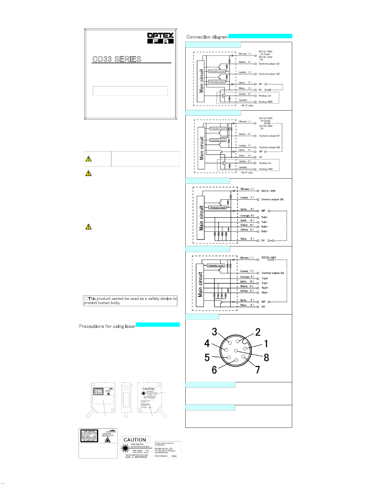
Connection diagram
Specifications
Laser type
Indicates a possible hazard that may result in death,
serious injury, WARNINGS or serious property damage
if the product is used without observing the stated
instructions.
● The light source of this product applies the visible light semiconductor
laser. Do not allow the laser beam to enter an eye, either directly or
reflected from reflective object. If the laser beam enters an eye, it m ay
cause blindness.
● Do not disassemble or modify the product since it is not designed to
automatically stop the laser emission when open. Disassembling or
modifying at customer's end it may cause personal injury, fire or electric
shock.
● This product is not an explosion proof c onstruction. Do not use the
product under flammable , explosive gas or liquid environment.
● Use of controls or adjustments or performance of procedures other
Precautions for using laser
■Laser label
This product is classified as Class 2 (Ⅱ) Laser Product by JIS
C6802/IEC/FDA Laser Safety Standard.
●Regulations in the USA
When exporting laser devices to the U SA, the USA laser control, FDA
(Food and Drug Administration) is applied. This product has been already
reported to CDRH (Center for Devices and Radiological Health). For
details, contact our customer service.
NPN type (Analogue/Voltage/Dual)
PNP type (Analogue/Voltage/Dual)
NPN type (RS422)
PNP type (RS422)
Pins configuration
*1 Defined with center strength 1/e2(13.5% ). There may be leak light other than the specified spot size.
The sensor may be damaged when there is a highly reflective object around the targets.
*2 Averaging: 64(High resolution), Sampling period:500μs, Object: white ceramic.
*3 Middle of measuring range, Object: white ceramic.
*4 Diameter of min bend cable is 40m m.
Installation
Caution for connection
1) Connect the lead wires correctly. The analog output wire must not be in contact
with any other wire. Do not turn on the power while wiring.
2) The blue wire(0V)and shield wire(analog GND) are internally connected.
Use the blue wire(0V) for the power supply and use the shield wire(analog GND) for
analog outpu t.
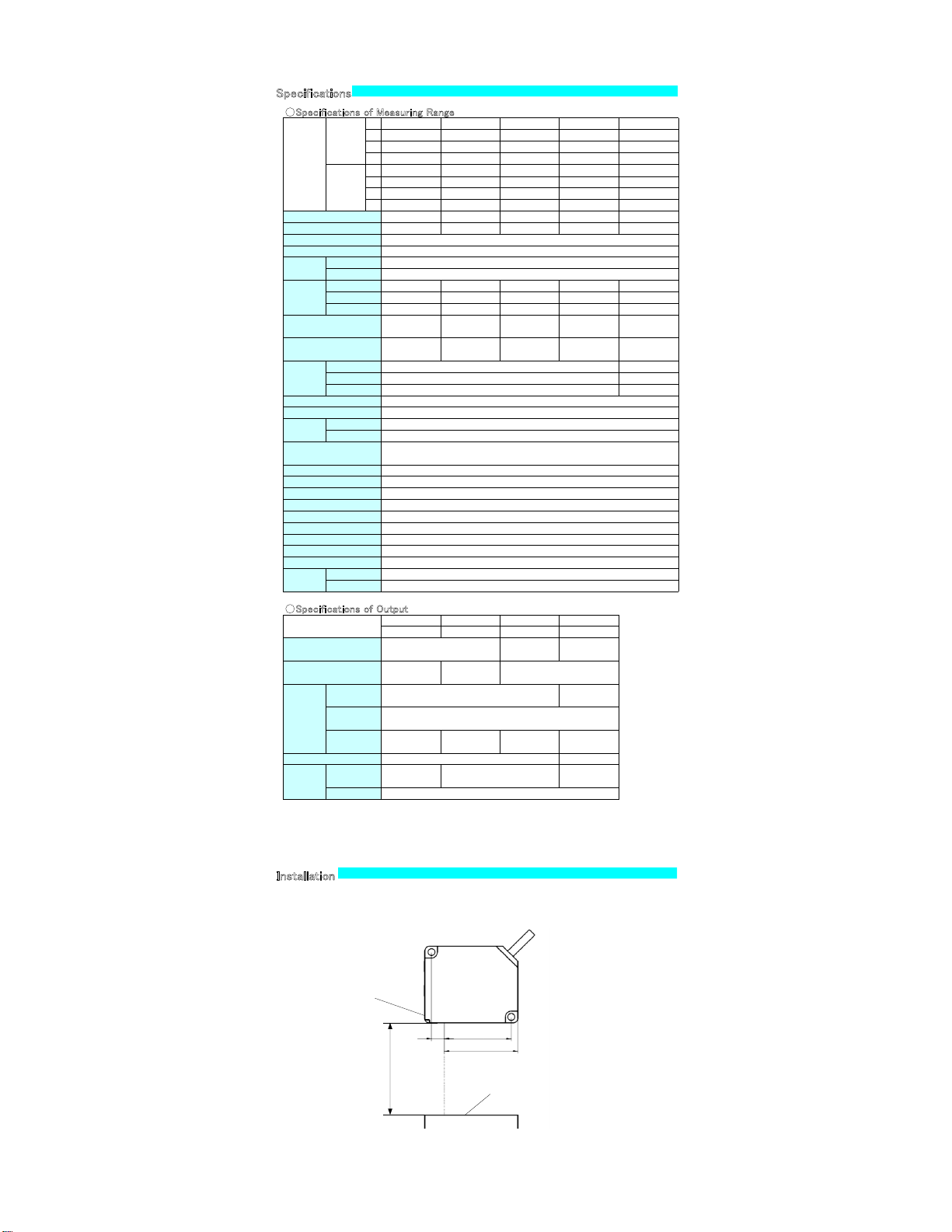
Install the sensor and adjust the light spot onto the measuring point so that the distance indicator turns ON ( orange ) at
the middle of measuring range.
Use M4 screw (tightening torque need to be under 0.8N・m).
・Adjust the sensor position so that it is set parallel to the surface of object obtain reliable measurement (see above).
・If there is any foreign object around the spot that is glossier than the measuring object, it may cause incorrect
measurement.
WARNING
WARNING
WARNING
optical axis
Surface of the object.
Distance indicator
shows orange when
object exists in the middle of
measuring range
(unit:mm)
Middle of
measuring
range
8.2
43.2
Carefully read and understand the safety precautions before operation. The
important information is provided to protect your h ealth and property. Do
not apply any other installing or operating procedure other than that
Mandatory Requirements
Safety Precautions
Meanings of Safety Symbol
●This product cannot be used as a safety device to
protect human body.
MF (multi functional ) input
Label-A
Label-B Label-C
Label-C
Label-B
Label-A
Ramco Innovations
800-280-6933
www.optex-ramco.com
Page 2
●Specifications of Measuring Range
①
CD33-30N(P) CD33-50N(P) CD33-85N(P) CD33-120N(P) C D33-250N(P)
①Press the Select button more than 5 seconds.
②
CD33-30N(P)A CD33-50N(P)A CD33-85N(P)A CD33-120N(P)A CD33-250N(P)A
③
CD33-30N(P)V CD33-50N(P)V CD33-85N(P)V CD33-120N(P)V CD33-250N(P)V
④
CD33-30N(P)-422 CD33-50N(P)-422 CD33-85N(P)-422 CD33-120N(P)-422 CD33-250N(P)-422
①
CD33-30CN(P) CD33-50CN(P) CD33-85C N(P) CD33-120CN(P) CD33-250CN(P)
②
CD33-30CN(P)A CD33-50CN(P)A CD33-85CN(P)A CD33-120C N(P)A CD33-250CN(P)A
③
CD33-30CN(P)V CD33-50CN(P)V CD33-85CN(P)V CD33-120C N(P)V CD33-250CN(P)V
④
CD33-30CN(P)-422 CD33-50CN(P)-422 CD33-85CN(P)-422 CD33-120CN(P)-422
CD33-250CN(P)
-
②Teach indicator lights up showing that Run status changes to Teach status.
30mm 50mm 85mm 120mm 250mm
±4mm ±10mm ±20mm ±60mm ±150mm
0.15×0.15mm 0.6×1.2mm 0.9×1.5mm 1.2×1.8mm 1.5×2.5mm
③Function indicator lights up.
0.1×0.1mm 0.5×1.0mm 0.75×1.25mm 1.0×1.5mm 1.75×3.5mm
0.15×0.15mm 0.4×0.9mm 0.6×1.0mm 0.5×0.8mm 2.0×4.5mm
7.5ms max.
18ms max.
54ms max.
④Select function by pressing Select button.
●Control panel
⑤Adjust or select value of function you need by pressing Set button.
⑥Then return to RUN by pressing by pressin g Select button continuously 5 seconds.
●Specifications of Output
Dual output Analogue Voltage RS422
①Press simultaneously both the Select button and Set button for 5 seconds.
CD33- ① CD33- ② CD33- ③ CD33- ④
RS422
②Both Run and Teach indicators come up.
RS422
③Function indicator Q1 lights up.
※Q2 lights up when it's RS42 2 type.
④Select a function by pressing Select button.
⑤Adjust or select the function by pressing Set button.
⑥Then return to RUN by pressing by press ing Select button and Set button continuously
5 seconds.
Type
Cable type
Connector type
Center
Measuring range
Light source Red laser Diode (wave length 655nm)
Peak power Max. output 1mW
Laser Class
IEC/JIS CLASS2
FDA CLASSⅡ
Spot size
(approx.
volume)
*1
Near
Middle
Far
Linearity *2
Sampling period
±0.1% F.S.
(F.S.=8mm)
±0.1% F.S.
(F.S.=20mm)
±0.1% F.S.
(F.S.=40mm)
±0.1% F.S.
(F.S.=120mm)
±0.3% F.S.
(F.S.=300mm)
Resolution *3
2μm
(Fast:4μm)
5μm
(Fast:8μm)
10μm
(Fast:15μm)
30μm
(Fast:45μm)
75μm
(Fast:150μm)
Response
time
Fast averaging: 1 time 5ms max.
Standard averaging: 16 times 12.5ms max.
High resolution averaging: 64 times 36.5ms max.
500 ,750(250mm type) /1000 /1500 /2000μs
Temperature Drift ±0.08% F.S./℃
Indicators
Distance Indicator
Bar graph LED
Analogue
Output Indicator
ON status : Orange
MF (multi functional) input
Laser off、Remote teaching、Sample H old (choose one function )
Response time :3ms max.
Sun light: 10,000 lx max. / Incandescent lamp: 3,000 lx max.
Vibration resistance 10 to 55 Hz, Double amplitude 1 .5 mm, 2 h for XYZ axes
Shock resistance
Circuit protection Reverse polarity、Over current
Protection Category IP67
Operating temp./humidity -10~+45℃/35~85%RH (No condensation or freezing)
Storage temp./humidity -20~+60℃/35~95%RH (No condensation or freezing)
Ambient Light
50G (500m/s
2
)
Warm up period 15min max.
Material PBT (Case) PMMA (Front window)
Weight
Cable type Approx. 65g (without cable)
Connector type
Approx. 70g
Type
Supply Voltage
DC12~24V
(+10%/-5%)
DC18~24V
(+10%/-5%)
DC12~24V
(+10%/-5%)
Current Consumption
55mA max. (DC24V)
85mA max. (DC24V)
including analog output
value
55mA max. (DC24V)
-
Voltage Dual Output
Control output
Q2
NPN/PNP Open collector 100mA max. /30V DC
(Residual voltage 1.8 V max.)
Analog output - 4~20mA 0~10V -
Interface -
Outputs
Control outputQ1NPN/PNP Open collector 100mA max. /30V DC
(Residual voltage 1.8 V max.)
Connection
Cable type *4
φ5 5core 2m
cable(PVC) AWG24
φ5 6core 2m cable(PVC) AWG24
φ5 8core 2m
cable(PVC) AWG24
Connector type
M12 8pin
Distance indicator has seven LEDs. LED indicate distance by moving at near to far side.
Status of LED Status of measurement Indicator
Out of range.
*This LED indicate when due to too
high/low reflection
Both side of red LED
lights up
Object is near of range.
Near side of red LED
lights up
Object is far of range.
Far side of red LED
lights up
Object is some far of range.
Far side of green LED
lights up
Object is middle of range.
Middle of orange LED
lights up
Specifications
*1 Defined with center strength 1/e2(13.5% ). There may be leak light other than the specified spot size.
The sensor may be damaged when there is a highly reflective object around the targets.
*2 Averaging: 64(High resolution), Sampling period:500μs, Object: white ceramic.
*3 Middle of measuring range, Object: white ceramic.
*4 Diameter of min bend cable is 40mm.
Installation
Install the sensor and adjust the light spot onto the measuring point so that the distance indicator turns ON ( orange ) at
the middle of measuring range.
Use M4 screw (tightening torque need to be under 0.8N・m).
・Adjust the sensor position so that it is set parallel to the surface of object obtain reliable measurement (see above).
・If there is any foreign object around the spot that is glossier than the measuring object, it may cause incorrect
measurement.
Functions of components
Receiving part
Emitting part
Control panel
Fixture Hole
Fixture Hole
Distance indicator
Teach indicator
Run indicator
・Distance indicator
・Laser emission indication
(ON during laser emission)
Select button
Set button
MF indicator
Control output2
Control output1
Select Function
Into Teach mode:
function indicator
ex.)A type
・Control output stops during teaching and setting period while Analog output works.
Reset the presettings
Turn on the power by pressing Select button and Set button at the same time and keeping
them pushed continuously 5 seconds. Then make sure if all the indicator blinks 3 times to
confirm cancel of all presettings.
●Teach mode
●Special Setting mode
+
ex.)A type
optical axis
Surface of the object.
Distance indicator
shows orange when
object exists in the middle of
measuring range
(unit:mm)
Middle of
measuring
range
8.2
43.2
ex.)A type
ex.)A type
Avg indicator
LED lights up , if receiving RS422 command.
Ramco Innovations
800-280-6933
www.optex-ramco.com
Page 3
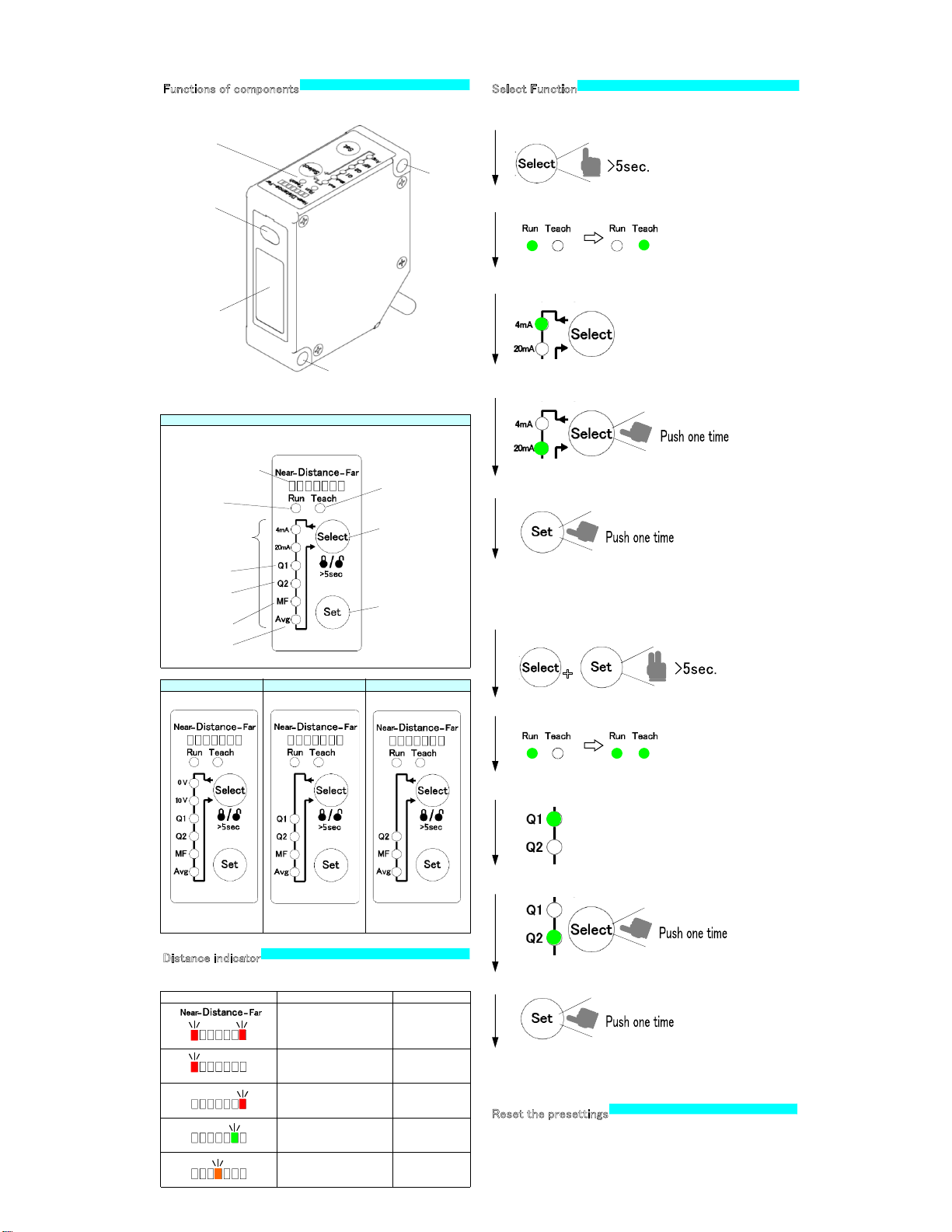
①Press the Select button more than 5 seconds.
②Teach indicator lights up showing that Run status changes to Teach status.
③Function indicator lights up.
④Select function by pressing Select button.
●Control panel
⑤Adjust or select value of function you need by pressing Set button.
⑥Then return to RUN by pressing by pressin g Select button continuously 5 seconds.
①Press simultaneously both the Select button and Set button for 5 seconds.
RS422
②Both Run and Teach indicators come up.
③Function indicator Q1 lights up.
※Q2 lights up when it's RS42 2 type.
④Select a function by pressing Select button.
⑤Adjust or select the function by pressing Set button.
⑥Then return to RUN by pressing by press ing Select button and Set button continuously
5 seconds.
Analogue
Voltage Dual Output
Distance indicator has seven LEDs. LED indicate distance by moving at near to far side.
Status of LED Status of measurement Indicator
Out of range.
*This LED indicate when due to too
high/low reflection
Both side of red LED
lights up
Object is near of range.
Near side of red LED
lights up
Object is far of range.
Far side of red LED
lights up
Object is some far of range.
Far side of green LED
lights up
Object is middle of range.
Middle of orange LED
lights up
Functions of components
Receiving part
Emitting part
Control panel
Fixture Hole
Fixture Hole
Distance indicator
Teach indicator
Run indicator
・Distance indicator
・Laser emission indication
(ON during laser emission)
Select button
Set button
MF indicator
Control output2
Control output1
Select Function
Into Teach mode:
function indicator
ex.)A type
・Control output stops during teaching and setting period while Analog output works.
Reset the presettings
Turn on the power by pressing Select button and Set button at the same time and keeping
them pushed continuously 5 seconds. Then make sure if all the indicator blinks 3 times to
confirm cancel of all presettings.
●Teach mode
●Special Setting mode
+
ex.)A type
ex.)A type
ex.)A type
Avg indicator
LED lights up , if receiving RS422 command.
Ramco Innovations
800-280-6933
www.optex-ramco.com
Page 4
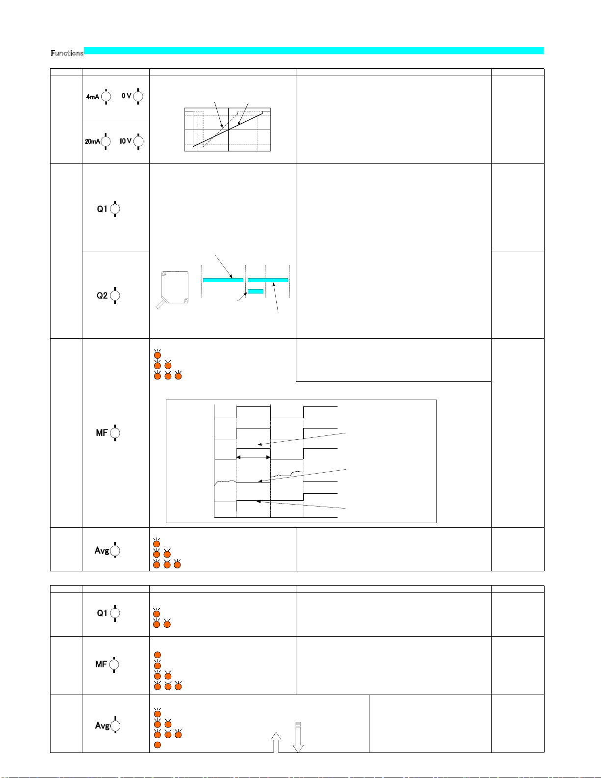
●Teach mode
Functions Factory Setting
●Special setting mode function
Functions Initial value
Functions indicated Details Settings and Adjustments
Span
Of the measurement
range
Near side: 4mA(0V)
Far side: 20mA(10V)
Input time Item
70 - 130ms The first point of span
170 - 230ms The second point of span
270 - 330ms
Q1: One point teachin
g
The second point of two points teaching must be completed in one minute with same
value as the first point.
370 - 430ms Q1:One point Reverse Teaching
Output setting
The output in the
measurement range
470 - 530 ms
Q2: One point teachin
g
The second point of two points teaching must be completed in one minute with same
value as the first point.
570 - 630 ms Q2:One Point Reverse Teaching
670 - 5000ms Offset*
5000ms and more Offset cancel
Settings and Adjustments
The output in the
measurement range
& Self-diagnosis *1
External input Laser OFF
Laser OFF
Averaging averaging: 16
Functions indicated Details
Sampling
period
500μs
750μs(CD33-250)
Analog output
when reflection
is too high/low
Analog output is fixed at
about 22mA(about 11V ).
One shot
trigger
Functions
Possible to coordinate analog output 4-20mA (0-10V) at an arbitrary
position in the rated range of measurement.
Select the function of the external input.
Average count setting
Blink Once : Fast (averaging 1 time)
Blink twice : Sta ndard
(
averaging 16 times)
Blink three times : High Res. (averaging 64 times)
①Push the Select button more than five seconds to get in Teach mode.
② Push the Select button and let 4mA (0V) indication turn on.
③ Set up the ob ject at the first point that you want to span, and push Set button.
④ 4mA (0V) indication flashes one time.
In the case of adjustment failure, the indication flashes for five seconds.
Try again getting back to ② of above.
⑤ Push the Select button and let 20mA (10V) indication turn on
⑥ Set up the object at the second point that you w ant to span, and push the Set button.
⑦20mA (0V) indication flashes one time.
In the case of adjustment failure, indication flashes for five seconds.
Try again getting back to ⑤ of above.
⑦ Push the Select button more than five seconds to return to Run mode
(Remarks)
When the Teach mode / special setting mode it returns to RUN if no operation in given for 60 seconds.
*1 Self-diagnosis output comes at the time of (1) laser stop (2) saturation by mirror-like object or (3) low sensitivity.
This function does not work when you set the output of Q2. Reset the product when you want to use
Self-diagnosis again.
Range of sensing of
One Point Teaching
Range of sensing of
Two Points Teaching
One point Two points
●One point teaching
①Push the Select button more than five seconds to enter Teach mode.
②Push the Select button and let Q1(Q2) indication turn on.
③Set the object in the position that you want to measure and push the Set button
④ Q1(Q2) indication flashes one time.
In the case of adjustment failure, indication flashes for five seconds.
Try again getting back to ② of above.
⑤Push the Select button more than five seconds to return to Run mode.
●Two points teaching
①Push the Select button more than five seconds to enter Teach mode.
②Push the Select button and let Q1(Q2) indication turn on
③Set up the object at the first point of the range that you want to measure and push
the Set button
④ Q1(Q2) indication flashes one time.
In the case of adjustment failure, the indication flashes for five seconds.
Try again getting back to ② of above.
⑤Q1(Q2)) which you Set up the object to the second point you want to measure, and push the Set button.
Q1(Q2) indication flashes two times.
In the case of the adjustment failure that the indication flashes for five seconds.
Try again getting back to ② of above.
⑥Push the Select button more than five seconds to return to Run mode.
●One point Reverse teaching
①Push the Select button more than five seconds to enter Teach mode.
②Push the Select button and let Q1(Q2) indication turn on
③Set the object in the position that you want to measure and push the Set button
more than five seconds .
④ Q1(Q2) indication flashes one time.
In the case of adjustment failure, the indication flashes five seconds.
Try again getting back to ② of above.
⑤Push the Select button more than five seconds to return to Run mode.
①Push the Select button more than five seconds to enter Teach mode.
②Push the Select button and let MF indication turn on.
③Choose the function you need by pushing Set button.
④Push the Select button more than five seconds to return to Run mode.
Set Analog output when impossible to measure due to too high/low reflection..
Blink Once : Analog output is fixed at about
22mA(about 11V ).
Blink twice : Th e last value is fixed and maintained,
One shot trigger is possible to select through external input.
On :One shot trigger
Blink Once : Laser OFF
Blink twice : Remote teaching
Blink three times : Sample Hold
Near Middle
Far
4mA/0V
12mA/5V
20mA/10V
Initial analog span
After adjustment
●Specification
Communication method RS422
Synchro system Asynchronous
Baud rate 9600/19200/38400/76800 bps *
Transmission c ode ASCII
Data length 8 bit
Stop bit length 1 bit
Parity check Nil
Data classification STX・ETX
●Communication Procedure
When PC sends a command to CD33 it sends back a response to the PC.
In principle one response is given to one command. When sending a command,
make sure if you receive the response to the previous command.
PC
CD33
Command Command
●Transmission Data Format (Command )
●Incoming Data Format (Response)
STX RESPONSE ETX
12 3
02H 03H
1 The code showing the head of incoming data (02H).
2 The response data is set to the transmitted command.
3 The code showing the completion of incoming d ata (03H).
The following four responses are for the written commands:
> (3EH) :Writings completed
? (3FH) :Writings rejected due to wrong command, etc.
(Numerical value) : Measurements or settings
STX COMMAND ETX
12 3
02H 03H
Reading out Setting/Measurement Value/Output Status
Writing the setting
12 3
02H 20H
STX COMMAND SPACE COMMAND ETX
1 The code showing the head of transmit data (02H).
2 Selects the command to transmit.
3 The code showing the completion of transmit data (03H).
1 The code showing the head of transmit data (02H).
2 Selects the command to transmit.
3 Shows the separation between Command and Command (20H).
4 Set the Setting/Measurement Value/Output Status.
Continuous readout of measurement value
Readout the measurements continuously at "START_MEASURE"
command. The response of this case never has STX, ETX. CR(0DH) is
inserted between the measurements.
(ex.)
85.0000<CR>85.0001<CR>85.0…
Sure to use the command "STOP_MEASURE" to stop the continuous
reading. Any othe r command will be valid until the stop command is set.
Continuous reading will not be activated simultaneously.
Remote teaching
Remote Teaching is possible through External Input. Input time of Remote
Teaching means change of settings.
*The current measurement value will be the central position of the measured analog value
by making offset. (A: 12mA / V: 5V)
* Baud rate :9600bps at factory set
Communication
Range of sensing of
One Point Reverse teaching
①Push the Select button more than five seconds to enter Teach mode.
②Push the Select button and let Avg. indication turn on.
③Choose the function by pushing Set button.
④Push the Select button more than five seconds to return to Run mode.
①Push the Select and set button at same time for more than five seconds
to enter Special setting mode
②Push the Select button and let Q1 indication turn on.
③Choose the function by pushing Set button.
④Push the Select and set button more than five seconds and to return to Run mode.
①Push the Select and set button at same time for more than five seconds
to enter Special setting mode
②Push the Select button and let MF indication turn on.
③Choose the function by pushing Set button.
④Push the Select and set button more than five seconds to return to Run mode.
Blink Once : Laser OFF
Blink twice : Remote teaching
Blink three times : Sample Hold
MF input
Sample Hold
Analog output
One Shot Trigger
Analog output
*Possible to choose One Shot Trigger by Special se tting mode.
Remote teaching
Laser output
T
Hold the output during inputs.
Update the output by edge of the input
and hold the output until next input
Near Far
Input time (refer to Remote Teaching)
set the range of Control Output.
One point teaching :From the position of the teaching - 0.15%(FS)
to the Near side of the sensing range.
Two points teaching :Between the position of the first point
teaching +0.15%(FS) and the position of
the second point teaching -0.15%(FS).
One point reverse teaching: From the position of the teaching
+0.15%(FS) to the Far side of the sensing
range.
Sampling period setting
①Push the Select button more than five seconds to
enter Teach mode.
②Push the Select button and let Avg. indication
turn on.
③Choose the function by pushing Set button.
④Push the Select and set button more than five seconds
to return to Run mode.
Blink Once : 500μs
Blink twice : 1000μs
Blink three times : 1500μs
On : 2000μs
Shorter sampling period
increases the response
and longer sampling
period enhances the
sensitivity.
High response
a
5
R]0
T
F
x
x
X
E
t
c
0
e
Ramco Innovations
800-280-6933
www.optex-ramco.com
Page 5
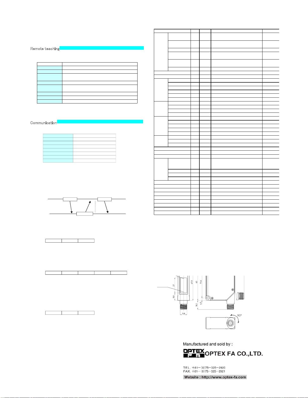
Input time Item
70 - 130ms The first point of span
170 - 230ms The second point of span
270 - 330ms
Q1: One point teachin
g
The second point of two points teaching must be completed in one minute with same
value as the first point.
370 - 430ms Q1:One point Reverse Teaching
470 - 530 ms
Q2: One point teachin
g
The second point of two points teaching must be completed in one minute with same
value as the first point.
570 - 630 ms Q2:One Point Reverse Teaching
670 - 5000ms Offset*
5000ms and more Offset cancel
Dimension
no operation in given for 60 seconds.
) saturation by mirror-like object or (3) low sensitivity.
This function does not work when you set the output of Q2. Reset the product when you want to use
Self-diagnosis again.
●Specification
●Command Table
Communication method RS422
Synchro system Asynchronous
Baud rate 9600/19200/38400/76800 bps *
Transmission c ode ASCII
Data length 8 bit
Stop bit length 1 bit
Parity check Nil
Data classification STX・ETX
●Communication Procedure
When PC sends a command to CD33 it sends back a response to the PC.
In principle one response is given to one command. When sending a command,
make sure if you receive the response to the previous command.
PC
CD33
Response
Command Command
●Transmission Data Format (Command )
●Incoming Data Format (Response)
STX RE SPONSE ETX
12 3
02H 03H
1 The code showing the head of incoming data (02H).
2 The response data is set to the transmitted command.
3 The code showing the completion of incoming d ata (03H).
The following four responses are for the written commands:
> (3EH) :Writings completed
? (3FH) :Writings rejected due to wrong command, etc.
(Numerical value) : Measurements or settings
STX COMMAND ETX
12 3
02H 03H
Reading out Setting/Measurement Value/Output Status
Writing the setting
12 3
02H 20H
STX COMMAND SPACE COMMAND ETX
45
03H
1 The code showing the head of transmit data (02H).
2 Selects the command to transmit.
3 The code showing the completion of transmit data (03H).
1 The code showing the head of transmit data (02H).
2 Selects the command to transmit.
3 Shows the separation between Command and Command (20H).
4 Set the Setting/Measurement Value/Output Status.
Continuous readout of measurement value
Readout the measurements continuously at "START_MEASURE"
command. The response of this case never has STX, ETX. CR(0DH) is
inserted between the measurements.
(ex.)
85.0000<CR>85.0001<CR>85.0…
Sure to use the command "STOP_MEASURE" to stop the continuous
reading. Any othe r command will be valid until the stop command is set.
Continuous reading will not be activated simultaneously.
Remote teaching
Remote Teaching is possible through External Input. Input time of Remote
Teaching means change of settings.
*The current measurement value will be the central position of the measured analog value
by making offset. (A: 12mA / V: 5V)
* Baud rate :9600bps at factory set
Communication
φ5-2mCable
A :6core
V :6core
Dual :5core
RS422 :8core
M12 8pin connector
* Avg indication will turn on whenever a
command response comes.
● Specifications and equipment are subject to change without any notice.
● For more information, questions and comments regarding products, please contact us below.
Beam emitting
axis
Beam receiving
area
Beam emitting
axis
Beam receiving
area
type*
Initial value
Ex
a
START_MEASURE CR -
85.0000[CR]8
5
STOP_MEASURE - -
[STX] > [ETX]
MEASURE R -
[STX] 85.0000
START_MEASURE_S CR -
85.0000 121[C
STOP_MEASURE_S - -
[STX] > [ETX]
MEASURE_S R -
[STX]85.0000
CR -
ON[CR]ON[C
R
--
[STX] > [ETX]
Q2 R -
[STX]ON[ETX
]
Q2_HI R -
[STX]105.000
0
Q2_LO R -
[STX]65.0000[
Q2_HI()60.000 W -
[STX] > [ETX]
Q2_LO()40.000 W -
[STX] > [ETX]
Q2 DEFAULT R ●
[STX] > [ETX]
AVG R -
[STX]FAST[E
T
AVG()FAST W -
[STX] > [ETX]
AVG()MEDIUM W ●
[STX] > [ETX]
AVG()SLOW W -
[STX] > [ETX]
MF R -
[STX]LSR_OF
F
MF()LSR_OFF W ●
[STX] > [ETX]
MF()SH W -
[STX] > [ETX]
MF()TEACH W -
[STX] > [ETX]
MF()OS W -
[STX] > [ETX]
ALARM R -
[STX]CLAMP[
ALARM()CLAMP W ●
[STX] > [ETX]
ALARM()HOLD W -
[STX] > [ETX]
W-
[STX] > [ETX]
W-
[STX] > [ETX]
--
[STX] > [ETX]
ON()500 W -
[STX] > [ETX]
ON()600 W -
[STX] > [ETX]
ON()700 W -
[STX] > [ETX]
ON()5000 W -
[STX] > [ETX]
RWR-
[STX]xxxxxxx
x
R-
[STX]xxxxxxx
x
W-
[STX] > [ETX]
R-
[STX]9.6K[ET
X
W 9.6
[STX] > [ETX]
R-
[STX]500US[
E
W 500
[STX] > [ETX]
Command Description
Read the
measurements
Start continuous reading of measurements
Stop continuous readi ng of measurements
Read the measurements
Start continuous reading of measurements and
sensitivity *1
Stop continuous reading of measurements and
sensitivity *1
Read the measurements and sensitivity
STAR T_Q2
Start continuous Q2 o utput
STOP_Q2
Stop continuous Q2 output
Q2 setting
Read Q2 output
Read actual setting of Q2 Hi
Read actual setting of Q2 Lo
Set Q2 Hi for example to 60mm *2
Set Q2 Lo for example to 40mm *2
Set Q2 to default (Self-diagnosis output)
Avg. setting
Read setting of the response time
Set response time to Fast
Set response time to Standard
Set response time to High resolution
Multi
functional
input
Read setting of multi functional inputs
Set to Laser off (default)
Set to Sample Hold
Set to external Teach
Set to one shot by trigger or command
Alarm
setting
Read actual setting for Alarm
Set Alarm to clamp
Set Alarm to Hold
RESET
Reset all settings to default settings
ON
Set MF active
OFF
Set MF inactive
External
Teach
Q2: One point teaching
The second point of two points of teaching ; Complete
input of the same command within one minute.
Q2:One Point Reverse teaching
Offset *8 *9
Offset cancel
SAVE
Save all setting
WRITE()xxxx
Write all se tting *3
SERIAL_NO
Read Serial number *4
USER DATA
Read user Data
USER_DATA()xxx
Write user data (max. 16 byte ASCII) *5
BIT_RATE
Read actual setting for Bit rate
BIT_RATE()9.6
Set baud rate *6
SAMPLE_RATE
Read actual setting for sam pling period
SAMPL E_RATE()500
Set sampling period *7
Command type = CR: Continuous reading command, R: Reading command, W: writi
The space (20H) is shown as ( ) for convenience.
*1 Sensitivity is automatically adjusted between the value of 0 and 223. (0 as Low limit,
Manual setting of sensitivity is not available.
*2 Input the distance to set by mm. Possible to input decimal four columns, but the se
t
over the detection performance becomes invalid.
*3 Write the values in turn as they have been read out in the SAVE.
*4 Reads out the serial numbers (11 digit) that is printed in the product label on the ba
c
*5 Up to 16byte by ASCII code
*6 Baud rate is 9.6kbps at factory set. Choose baud rate among( 9.6/19.2/38.4/57.6/76
*7 Sampling period is 500μs at factory set. Choose sampling period among ( 500/100
0
(CD33-250 750/1000/1500/2000μs 750μs at factory set)
*8 While Offset is activated, it will output displacement data including minus sign for th
e
600-8815 Kyoto, Shimogyo, Awata Chudoji 91, Japan
Ramco Innovations
800-280-6933
www.optex-ramco.com
 Loading...