

Page 1
No.59-2686-0 1802-16
INSTALLATION INSTRUCTIONS
Quick Reference
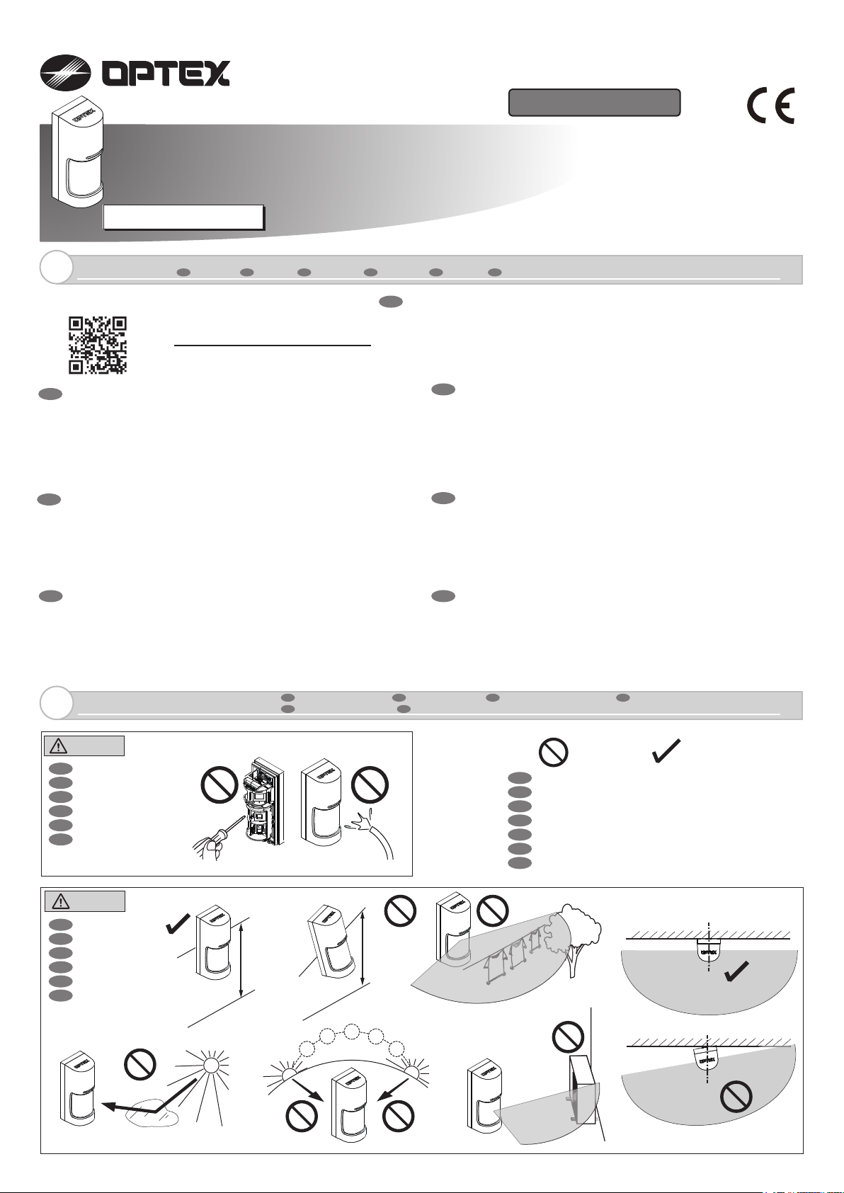
180°WIDE ANGLE OUTDOOR DETECTOR
180°WIDE ANGLE OUTDOOR DETECTOR
WX Infinity seriesWX Infinity series
WIRED MODEL
FR
Introduction
1
Introduction
DE
Einleitung
Full information, with multilanguage, available in ;
http://navi.optex.net/manual/50196
• Cette “Quick Reference” est la partie des instructions
FR
d’installation entières qui guide les procédures d’installati
les installateurs.
• Obtenez les informations complètes avec multi-langue des
instructions d’installation dans le site Web.
• Si vous avez besoin d’un guide pour le fonctionnement du
système dans son ensemble, s’il vous plaît consulter votre
installateur de l’ensemble du système.
IT
• Questa “Guida rapida” è la parte di tutto il istruzioni di
installazione che guida le procedure di installazione per gli
installatori.
• Ottenere le informazioni complete con il multi-linguaggio delle
istruzioni di installazione nel sito web.
• Se occorre una guida per il funzionamento del sistema nel suo
complesso, cons
• Este “Referência Rápida” é parte de toda as instruções de
PT
instala
ção que orienta os procedimentos de instalação para os
instaladores.
• Obter as informações completas com multi-idioma das
instruções de instalação no web site.
• Se você precisa de um guia para a operação do sistema como
um todo, por favor consulte o seu instalador de todo o sistema.
ultare l’installatore dell’intero sistema.
IT
Introduzione
ES
Introducción
EN
on pour
EN
WXI-ST: Standard model
WXI-AM: +Anti-masking
PT
• This “Quick Reference” is the part of the entire installation
instructions that guides the installation procedures for installers.
•
Get the full information with multi-language of the installation
instructions in the web site.
If you need a guide to the operation of the whole system,
•
please consult your installer of the entire system.
DE
ES
NL
Introdução
NL
Inleiding
• Dieses “Quick Reference” ist der Teil der gesamten
Installationsanweisungen, die die Installationsverfahren für
Installateure führt.
• Holen Sie sich die vollständige Information mit mehrsprachiger
nstallationshinweise in der Website.
der I
• Wenn Sie einen Leitfaden für den Betrieb des Systems als
Ganzes benötigen, wenden Sie sich bitte an Ihren Installateur
des gesamten Systems.
• Este “Referencia rápida” es la parte de la totalidad de las
instrucciones de instalación que guía los procedimientos de
instalación para los instaladores.
• Obtener la información completa con multi-idioma de las
instrucciones de instalación en el sitio web.
• Si necesita una guía para el funcionamiento del sistema en su
conjunto, por favor consulte a su instalador de todo el sistema.
• Deze “Snelle referentie” maakt deel uit van de totale
installatieaanwijzingen die de installateur door de
installatieprocedures leiden.
• Krijg de volledige meertalige informatie van de
installatieaanwijzingen van de websi
te.
• Als u richtlijnen nodig hebt over de werking van het gehele
systeem, raadpleeg dan de installateur van het gehele systeem.
Manufacturer’s statement
2
Warning
FR
Avertissement
DE
Warnung
IT
Avvertenza
ES
Aviso
PT
Aviso
NL
Waarschuwing
Caution
FR
Attention
DE
Vorsicht
IT
Attenzione
ES
Precaución
PT
Cuidado
NL
Voorzichtig
0.8 - 1.2 m
(2′7″-4′)
Parallel
FR
Déclaration du fabricant DE Herstellererklärung
PT
Declaração do fabricante
Tilt
NL
Mededeling van de fabrikant
IT
Dichiarazione del costruttore
EN
Prohibition
FR
Interdiction
DE
Verbot
IT
Divieto
ES
Prohibición
PT
Proibição
NL
Verbod
ES
Declaración del fabricante
Recommendation
Recommandation
Empfehlung
Raccomandazione
Recomendación
Recomendação
Aanbeveling
Page 2
Installation
3
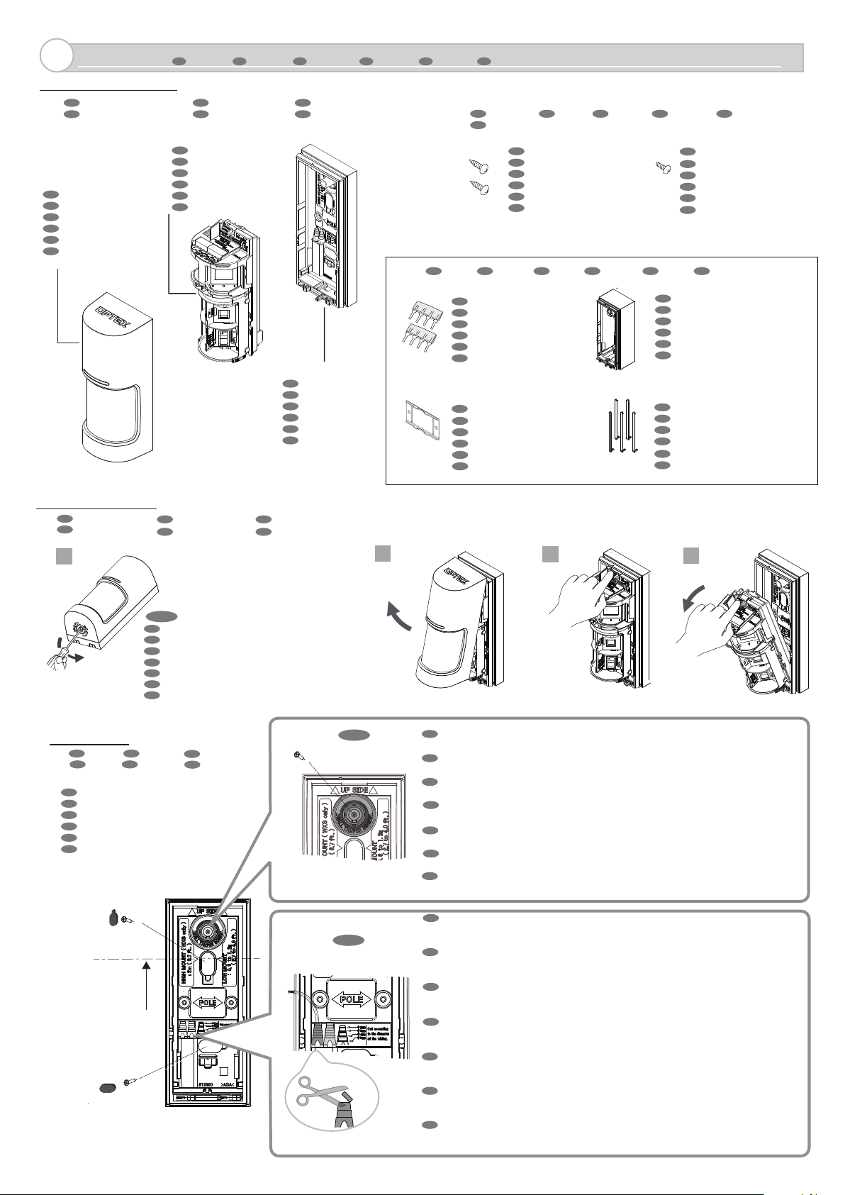
3-1. Parts identifications
FR
Identification des pieces Teile-identifikatioon
ES PT
Identificación de los partes
Cover unit
FR
Unité de couverture
DE
Abdeckungseinheit
IT
Unità di copertura
ES
Unidad de cubierta
PT
Unidade de cobertura
NL
Afdekkingseenheid
FR
Installation DE Installation
DE
Identificaão de peças Identificatie onderdelen
Main unit
FR
Unité principale
DE
Haupteinheit
IT
Unità pr incipale
ES
Unidad principal
PT
Unidade principal
NL
Hoofdeenheid
IT
Installazione
IT
Descrizione delle par ti
NL
Base unit
FR
Unité de base
DE
Grundeinheit
IT
Unità base
ES
Unidad base
PT
Unidade base
NL
Basiseenheid
ES
Instalación
<Options>
PT
Instalação
<Accessories>
FR
Options DE Optionen IT Opzioni ES Opciones PT Opçóes NL Opties
Plug- in EOL [PEU]
Pole mount plate [PMP-01]
NL
Installatie
FR
Accessoires DE Zubehör IT Accessori ES Accesorios PT Acessórios
NL
Accessoires
Mounting screw (4 × 20 mm)
FR
Vis de montage
DE
Befestigungsschraube
IT
Viti di montaggio
ES
Tornillo de montaje
PT
Parafusos de montagem
NL
Bevestigingsschroef
FR
Brancher sur EOL
DE
EOL-stecker
IT
Fine linea (EOL) a innesto
ES
Plug-in EOL
PT
Plug-in EOL
NL
Insteek- EVL
Lock screw (3 × 12 mm)
Back box [WXI-BB]
FR
Arrière du boiter
DE
Rückkasten
IT
Scatola posteriore
ES
Caja trasera
PT
Caixa traseira
NL
Achterkant van de kast
Area masking plate [MKP-01]
FR
FR
Plaque de montage sur poteau
DE
Pfosten Montageplatte
IT
Base di montaggio su palo
ES
Sopor te de montaje en poste
PT
Placa de montagem no poste
NL
Paal montageplaat
Plaque de masquage
DE
Flächenmaskierungsplatte
IT
Piastra per mascheratura di area
ES
Placa de enmascaramiento de área
PT
Placa de máscara de área
NL
Area masking plate
FR
Vis de blocage
DE
Verriegelungsschraube
IT
Vite di bloccaggio
ES
Tornillo de bloqueo
PT
Parafuso de fixação
NL
Borgschroef
3-2. Before mounting
FR
FR
Avant l’montage
ES
ES
Antes de la montaje
1
Unlock
3-3. Mounting
FR
Montage DE Montage
ES
Montaje PT Montagem
Wall mount
FR
Montage mural
DE
Wandmontage
IT
Montaje a parete
ES
Montagem en pared
PT
Montagem na parede
NL
Wandmontage
FR
DE
DE
Vor der montage
PT
Antes da mont agem NL Voor de montage
PT
IT
IT
Prima del’ montaggio
NL
NOTE
EN
Remove the lock screw if it is used.
FR
Retirez la vis de blocage si elle est utilisée.
DE
Entfernen Sie die Sicherungsschraube, falls verwendet.
IT
Rimuovere la vite di bloccaggio se utilizzata.
ES
Retire el tornillo de seguridad si se usa.
PT
Remova o parafuso de bloqueio se for utilizado.
NL
Verwijder de borgschroef indien gebruikt.
IT
Montaggio
NL
Bevestiging
Wall tamper
NOTE
2
EN
• The wall tamper is activated when the shown part is broken and remains
on the mounting surface.
FR
• Le autoprotection mural est activé lorsque la pièce d'exposition est cassée
et reste sur la surface de montage.
DE
• Der Wand sabotage wird aktiviert, wenn der Vorführteil gebrochen ist
und auf der Montagefläche verbleibt.
IT
• Il manomissione muro viene attivato quando la parte dello spettacolo è rotta
e rimane sulla superficie di montaggio.
ES
• El sabotaje de la pared se activa cuando la parte del espectáculo se rompe
y permanece en la superficie de montaje.
PT
• A sabotagem de parede é ativada quando a parte de exibição está quebrada
e permanece na superfície de montagem.
NL
• De muursabotage wordt geactiveerd als het onderdeel van de show wordt
verbroken en op het montageoppervlak blijft.
3
4
Mounting height 0.8 - 1.2 m
(1.0 m is recommended)
2
NOTE
Wire hole
EN
• Cut the bushing to the size matching the wire diameter according to the indication.
• Use the left for the first wire, and cut off to use the right bushing for the second wire
if necessary.
FR
• Couper la douille à la taille correspondant au diamètre du fil selon l'indication.
• Utilisez la douille gauche pour le premier fil, et coupez pour utiliser la douille droite pour
le deuxièmefil si nécessaire.
DE
• Schneiden Sie die Buchse entsprechend der Angabe auf den Drahtdurchmesser ab.
• Verwenden Sie die linke Buchse für den ersten Draht und schneiden Sie sie ab,
um gegebenenfalls die rechte Buchse für den zweiten Draht zu verwenden.
IT
• Tagliare la boccola alla misura corrispondente al diametro del filo in base all'indicazione.
• Utilizzare la boccola sinistra per il primo filo e tagliare per utilizzare la boccola destra per
il secondo filo, se necessario.
ES
• Corte el casquillo al tamaño correspondiente al diámetro del cable según la indicación.
• Use el casquillo izquierdo para el primer cable y corte para usar el casquillo correcto para
el segundo cable si es necesario.
PT
• Corte a bucha no tamanho correspondente ao diâmetro do fio de acordo com a indicação.
• Use a bucha esquerda para o primeiro fio e corte para usar a bucha direita para o segundo
fio, se necessário.
NL
• Snijd de bus op de maat die overeenkomt met de draaddiameter volgens de aanduiding.
• Gebruik de linkerbus voor de eerste draad en snij af om zo nodig de rechterbus
voor de tweede draad te gebruiken.
Page 3
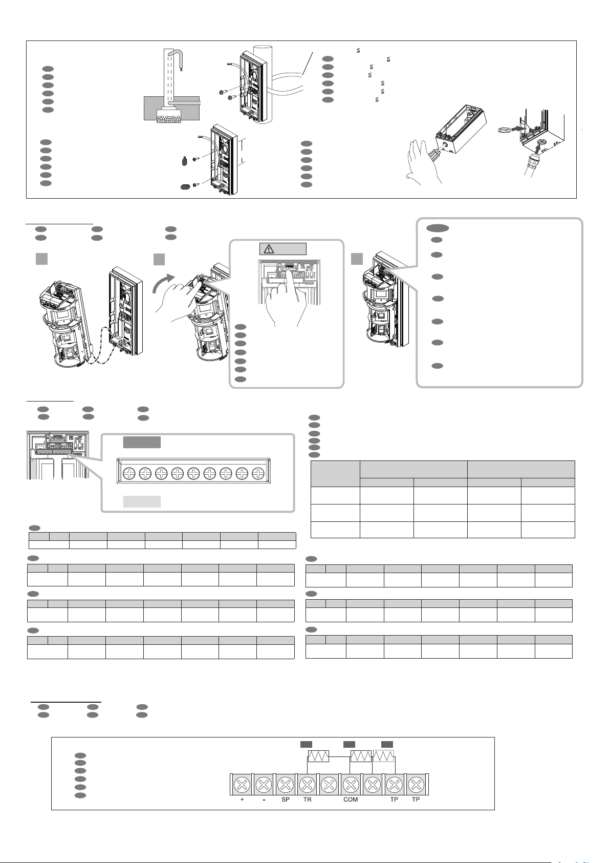
<< With option parts >>
Pole mount
< With option pole mount plate >
FR
Montage sur poteau
DE
Pfostenmontage
IT
Montaggio su palo
ES
Montaje en poste
PT
Montagem no poste
NL
Paalmontage
Electric gang box mount
FR
Montage boîte de gang électrique
DE
Elektrische Gerätedose montieren
IT
Montaggio scatola di giunzione elettrica
ES
Montaje en caja eléctrica eléctrica
PT
Montar a c aixa de gangues elétrica
NL
Bevestiging elektrische groepenkast
Pitch
83.5 mm
(3.29 inch)
Metal band
FR
Ruban métallique
DE
Metal-Band 23mm (1 Zoll) in der Breite
IT
Metal band 23 mm (1 pollice) di larghezza
ES
Banda de metal 23 mm (1 pulgada) de ancho
PT
Banda de metal 23 mm (1 polegada) de largura
NL
Metalen band 23 mm (1 inch) breed
Conduit installation
< With option back box >
FR
Installation conduit
DE
Conduit-Installation
IT
Installazione Conduit
ES
Instalación de conectores
PT
Instalação do conduíte
NL
Installatie van de kabelgoten
23 mm (1 inch) in width
23 mm (1 pouce) de largeur
3-4. Assembling
FR
Assemblage DE Zusammenstellung IT Assemblaggio
ES
Asamblea
PT
Assembléia
1
Fasten the two bosses securely.
2
NL
Assemblage
EN
Push the indication firmly.
FR
Poussez l'indication fermement.
DE
Drücken Sie die Anzeige fest.
IT
Spingere l'indicazione con decisione.
ES
Presione la indicación firmemente.
PT
Pressione a indicação firmemente.
NL
Duw de indicatie stevig vast.
3-5. Wiring
FR
Câblage
ES
Cableado
EN
(+) (-) SP TR AL(L) COM AL(R) TP
Power
FR
(+) (-) SP TR AL(L) COM AL(R) T P
DE
PT
Spare
Verkabelung
Fiação
Alimentation En réserve Problème Alarme (L) Commun Alarme (R)
IT
(+) (-) SP TR AL(L) COM AL(R) T P
Alimentazione
PT
(+) (-) SP TR AL(L) COM AL(R) TP
Alimentação
Libero Guasto Allarme (L)
Sobress
-alente
IT
Collegamenti
NL
Bedrading
WXI-ST
SP
+ -
+ - SP
WXI-AM
Trouble Alarm(L)
Problema
Alarme (L) Comum Alarme (R) Sabotagem
SP
AL(L)
TR AL(L)
Common Alarm(R)
Comune
COM AL(R) TP TP
COM AL(R) TP TP
Allarme (R)
Caution
Tamper
Auto
-protection
Antimano
-missione
NOTE
EN
Pry to remove with a screw driver,
when it gets caught by a tilt insertion.
FR
3
< Power cable length > Unit: m (ft.)
FR
Longueur du câble d’alimentation Unité: m (pieds)
DE
Stromkabellänge Einheit: m (Füße)
Lunghez za del cavo di alimentazione Unità: m (piedi)
IT
Longitud del cable de alimentación Unidad: m (pies)
ES
PT
Comprimento do cabo de alimentação Unidade: m (pés.)
Lengte netsnoer Eenheid: m (voet)
NL
Wire gauge
WXI-ST
Current draw 21 mA
Soulevez pour enlever avec un tournevis,
lorsque l'unité principale est attrapée par
une insertion d'inclinaison.
DE
Wischen Sie mit einem Schraubenzieher,
wenn die Haupteinheit durch eine Neigung
eingeklemmt wird.
IT
Fare leva per rimuovere con un cacciavite,
quando l'unità principale viene catturata da
un inserimento di inclinazione.
Haga palanca para quitar con un destornillador,
ES
cuando la unidad principal queda atrapada por
una inserción de inclinación.
PT
Pry para remover com um parafuso, quando a
unidade principal é pega por uma inserção de
inclinação.
Wrikken om te verwijderen met een
NL
schroevendraaier, wanneer de hoofdeenheid
wordt gevangen door een kanteling invoeging.
WXI-AM
Current draw 23 mA
12V DC 14V DC 12V DC 14V DC
AWG 22
2
)
(0.33 mm
AWG 20
2
(0.52 mm
)
AWG 18
2
(0.83 mm
)
DE
(+) (-) SP TR AL(L) COM AL(R) TP
Strom
-einspeisung
ES
(+) (-) SP TR AL(L) COM AL(R) T P
Alimentación
NL
(+) (-) SP TR AL(L) COM AL(R) TP
Stroomvoor
-ziening
(No user)
270
(890)
430
(1 410)
690
(2 260)
590
(1 940)
940
(3 080)
1 490
(4 890)
250
(820)
390
(1 280)
630
(2 070)
Reserve Störung Alarm (L) Gewöhnlich Alarm (R)
Libres
Problema
Ruimte Problemen Alarm (L)
Alarma (L)
Común Alarma (R)
Gemeens
-chappelijk
Alarm (R) Sabotage
540
(1 770)
850
(2 790)
1 360
(4 460)
Sabotage
-ausgang
Antisabotaje
3-6. EOL options
FR
EOL options DE EOL options IT EOL opzioni
ES
EOL opciónPT EOL opçóes NL EVL-opties
<< With additional parts >>
< Without plug-in EOL (PEU) >
FR
Sans branchez EOL (PEU)
DE
Ohne Plug-in EOL (PEU)
IT
Senza EOL plug-in (PEU)
ES
Sin plug-in EOL (PEU)
PT
Sem ligue EOL (PEU)
NL
Zonder insteek-EVL
TR Trouble AL Alarm TP Tamper
AL(L) AL(R)
3
Page 4

<< With option parts >>
< Using plug-in EOL (PEU) >
FR
Utilisation branchez EOL (PEU)
DE
Mit Plug-in EOL (PEU)
IT
Utilizzo di plug-in EOL (PEU)
ES
Mediante plug-in EOL (PEU)
PT
Usando ligue EOL (PEU)
NL
Met gebruik insteek- EVL (PEU)
[1] Control panel
[4] Plug-in EOL
TR Trouble
[2] Triple EOL
AL(L)
AL Alarm
[3] Double EOL
AL(R)
TP Tamper
[5] Insert direction
Trouble
TR
Common
COM
AL Alarm
TP Tamper
[6] Type
FR
[1]
Panneau de c ontrôle
Triple EOL
[2]
Double EOL
[3]
[4]
Branchez EO L
[5]
Insérer direction
Type
[6]
Problème
TR
Alarme
AL
TP Autoprotection
Commun
COM
ES
ES
[1]
Panel de control
EOL triple
[2]
EOL doble
[3]
Plug-in EOL
[4]
Direcc ión de inserció n
[5]
Tipo
[6]
Problema
TR
Alarma
AL
Antisabotaje
TP
Común
COM
DE
DE
[1]
Steuerpult
[2]
Triple EOL
[3]
Doppel EO L
[4]
Plug-in EOL
[5]
Insert Richtungr t
[6]
Art
Störung
TR
Alarme
AL
TP
Sabotageausgang
Gewöhnlich
COM
PT
[1]
Painel de c ontrole
[2]
EOL triplo
[3]
EOL duplo
[4]
Ligue EOL
[5]
Inserir direção
[6]
Tipo
TR
Problema
AL
Alarme
TP
Sabotagem
Comum
COM
IT
[1]
Pannello di controllo
Triple EOL
[2]
Doppia EO L
[3]
Plug-in EOL
[4]
[5]
Inserire la direzione
Tipo
[6]
TR
Guasto
AL
Allarmi
TP
Antimanomissione
COM
Comune
NL
[1]
Bedieningspaneel
[2] Drievoudige EVL
[3] Dubbele EVL
Insteek- EVL
[4]
[5]
Richting voor insteken
Type
[6]
Problemen
TR
Alarm
AL
Sabotage
TP
COM
Gemeenschappelijk
4
Settings
FR
Réglages DE Einstellungen
IT
Impostazione
4-1. PIR detection area
FR
PIR zone de detection DE PIR Erfassungsbereich IT PIR area di r ilevamento
ES
PIR área de detección PT PIR área de detecção NL Detectiegebied PIR
Left side
Side view
FR
Vue de coté
DE
Seitenansicht
IT
Vista laterale
ES
Vista lateral
PT
Vista lateral
NL
Zijaanzicht
Unit: m (f t.)
FR
Unité: m (pieds)
DE
Einheit: m (Füße)
IT
Unità: m (piedi)
ES
Unidad: m (pies)
PT
Unidade: m (pés)
NL
Eenheid: m (voet)
4-2. PIR area masking
FR
PIR zone masquage DE PIR Bereichsmakierung IT PIR area mascheramento
ES
PIR área mascaramento PT PIR área mascarament NL PIR gebied maskeren
12.0 10.0 5.0 0
(40) (33) (17)
12.0 10.0 5.0 0
12.0 10.0 5.0 0
12.0 10.0 5.0 0
12.0 m (40 ft.)
12.0 10.0 5.0 0
ES PT NL
Configuración Configração
2.5 m (8 ft.)
1.0
(3)
3.5 m (12 ft.)
6.0 m (20 ft.)
8.5 m (28 ft.)
Instellingen
2.5 m (8 ft.)
1.0
(3)
0 5.0 10.0 12.0
(17) (33) (40)
3.5 m (12 ft.)
0 5.0 10.0 12.0
6.0 m (20 ft.)
0 5.0 10.0 12.0
8.5 m (28 ft.)
0 5.0 10.0 12.0
12.0 m (40 ft.)
0 5.0 10.0 12.0
Right side
< With the area adjustment shutter >
FR
Avec le volet d'ajustement de zone
IT
Con l'otturatore di regolazione dell'area
PT
Com o obturador de ajuste da área
4
Default
DE
a
Mit der Flächenjustierung
ES
Con el obturador de ajuste de área
NL
Met de gebiedsafhankelijke sluiter
b
c
d
e
f
g
h
i
j
Left = “d”
Right = “k”
a
b
Left = Default
c
Right = “d”
e
f
g
h
i
j
k
l
m
n
Page 5

< With the area masking plate (option) [MKP-01] >
FR
Avec la plaque de masquage de zone (inclus)
DE
Mit die Flächenmaskierungsplatte (inbegriffen)
IT
Con la piastra di mascheratura dell'area (incluso)
ES
Con la placa de enmascaramiento del área (incluido)
PT
Com a placa de máscara de área (incluído)
NL
Met de maskeerplaat voor het gebied (Inbegrepen)
For example
Area
“h” masking
n
m
1
2
l
k
Top view
j
i
h
g
“h”
Area
f
masking
e
d
c
b
a
4-3. Switch setting
FR
Réglages des interrupteur
IT
Impostazioni degli interruttori
PT
Ajuste da chave
WXI-ST
WXI-AM
EN
Default
FR
Défaut
DE
Werkseinstellung
IT
Predefinita
ES
Defecto
PT
Configuração de fábrica
NL
Fabrieksinstellingen
DE
Schaltereinstellungen
ES
Ajuste del conmutador
NL
Instellingen switches
FR
WXI-ST
WXI-AM
Article
1 2 3 4
1 2 3 4
LED Alarm
ON ON N.O.
OFF OFF
IT
WXI-ST
WXI-AM
Articolo
1 2 3 4
1 2 3 4
Alarme
LED
ON ON N.A.
OFF OFF
PT
WXI-ST
WXI-AM
1 2 3 4
1 2 3 4
Item LED Alarme
ON ON
OFF OFF N.F.
N.C.
N.C.
N.A.
Indivi-
duelles
ON
OFF
Indivi-
duali
ON
OFF
Indivi-
duais
ON
OFF
EN
Comptage
d'impulsions
1
2
Conteggio
degli impulsi
1
2
Contagem
de pulsos
1
2
WXI-ST
WXI-AM
1 2 3 4
1 2 3 4
Item LED Alarm
ON ON N.O.
OFF OFF
5 6
5 6 7
Usage
futur
8
Anti-
masquage
ON
OFF
6
5
5 6 7
Utilizzo
futuro
Anti-
8
maschera
mento
ON
OFF
6
5
5 6 7
Uso
futuro
8
Anti-mascara
mento
ON
OFF
N.C.
Individual
Pulse count
ON
OFF
DE
WXI-ST
WXI-AM
Artikel LED
ON ON N.O.
OFF OFF
ES
WXI-ST
WXI-AM
Ítem LED Alarma
ON ON
OFF OFF
NL
WXI-ST
WXI-AM
Item LED
ON ON N.O.
OFF OFF
6
5
5 6 7
1
use
2
ON
OFF
Anti-masking
Future
1 2 3 4
1 2 3 4
Alarm
Einzelne
ON
OFF
N.C.
1 2 3 4
1 2 3 4
Individuales
N.O.
ON
OFF
N.C.
1 2 3 4
1 2 3 4
Indivi-
Alarm
duele
ON
N.C.
OFF
8
Pulszahl
1
2
Cuenta
de pulso
1
2
Pulse
count
1
2
6
5
5 6 7
Zukünftiger
Gebrauch
6
5
5 6 7
Uso
futuro
6
5
5 6 7
Toekom
stig
gebruik
8
Anti-ma skierung
ON
OFF
8
Anti-enmas
caramiento
ON
OFF
8
Anti-
maskering
ON
OFF
4-4. PIR sensitivity
FR
Sensibilité PIR
IT
Sensibilità PIR
PT
Sensibilidade do PIR
EN
Default
FR
Défaut
DE
Werkseinstellung
IT
Predefinita
ES
Defecto
PT
Configuração de fábrica
NL
Fabrieksinstellingen
NOTE
1 2 3 4 5 6 7 8
DE
PIR-Empfindlichkeit
ES
Sensibilidad PIR
NL
PIR gevoeligheid
Left side
KSD82S
IT
Alta
Media
Bassa
Middel matig
Right side
High
Middle
Low
FR DE
Haute Hoch
Moyen Mitte l
Faible Niedrig
ES PT NL
Alta Alta Hoog
Media
Média
Baja Baixa Laag
Lock screw
EN
The lock screw (included) can prevent accidental unlocking the cover.
FR
La vis de blocage (incluse) peut empêcher le déverrouillage accidentel de l'unité de couverture.
DE
Die Verriegelungsschraube (inbegriffen) können Entriegeln der Abdeckungseinheit versehentlichen verhindern.
IT
La vite di bloccaggio (incluso) può impedire lo sblocco accidentale dell'unità di copertura.
ES
El tornillo de bloqueo (incluido) puede evitar el desbloqueo accidental de la unidad de la cubierta.
PT
O parafuso de bloqueio (incluído) pode impedir o desbloqueio acidental da unidade de cobertura.
NL
De borgschroef (inbegrepen) kan voorkomen dat per ongeluk ontgrendelen van de afdekeenheid.
5
Page 6

FR
Checking
5
FR
5-1. Walk test
FR
Test de marche
IT
Prova di movimento Prueba de funcionamiento
PT
Test de caminhada
DE
ES
NL
Gehtest
Looptest
3
DE
DE
Überprüfung
IT
2
Check that LED lights for 2 seconds when the intended object is detected.
FR
FR
Vérofoer que les lumières LED pour 2 secondes lorsque l’objet visé est détecté.
DE
DE
Prüfen Sie, ob LED- Leuchten für 2 Sekunden, wenn das beabsichtigte Objekt erkannt wird.
IT
IT
Controllare che le luci LED per 2 secondi quando viene rilevato l’oggetto desiderato.
ES
ES
Comprobar que las luces LED de 2 segundos cuando se detecta el objeto pretendido.
PT
Verifique se as luzes LED para 2 segundos quando o objeto pretendido for detectado.
NL
PT
Controleer dat de LED-lampjes gedurende 2 seconden oplichten wanneer het bedoeld voorwerp wordt waargenomen.
ES
ES
Comprobación
PT
PT
Checagem
Close the cover unit, “Walk test” starts automatically.
1
FR
FR
DE
DE
IT
IT
ES
ES
PT
NL
PT
NL
NL
Controleren
Fermez l’unité de couverture, “Test de marche” démarre automatiquement.
Schließen Sie die Abdeckungseinheit, “Gehtest ” startet automatisch.
Chiudere l’unità di coper tura, “Prova di movimento” avvia automaticamente.
Cierre la unidad de cubierta, “Prueba de funcionamiento” se inicia automáticamente.
Feche a unidade de cobertura, “Test de caminhada” inicia-se automaticamente.
Sluit de afdekkingseenheid terung, de “Looptest” star t automatis
IT
“Walk test” expires 3 minutes after closing the face cover, with LED blinks for 5 seconds.
FR
FR
“Test de marche” expire 3 minutes après le fermeture le couver ture du visage, avec LED clignote pendant 5 secondes.
DE
DE
“Gehtest” gültig bis 3 Minuten nach die Gesichts-Abdeckung zu schließen, mit LED für 5 Sekunden blinkt.
IT
IT
“Prova di movimento” scade 3 minuti dopo aver chiuso la coper tura del fronte, con LED lampeggia per 5 secondi.
ES
“Prueba de funcionamiento” expira 3 minutos después de cerrar la cubierta de la cara, con el LED parpadea durante 5 segundos.
ES
“Test de caminhad
PT
NL
De “Looptest” verstrijkt 3 minuten na het sluiten van het gezicht te bedekken, waarbij de LED gedurende 5 sec onden knippert.
PT
a” expira 3 minutos depois de fechar a cobrir o rosto, com LED pisca durante 5 segundos.
ch.
5-2. LED indication
FR
LED d’ indication LED–Anzeige
WXI-ST
WXI-AM
Red
Detection area
6
Top view
FR
Vue de dessus
DE
Draufsicht
IT
Vista dall’alto
ES
Vista superior
PT
Vista de cima
NL
Bovenaanzicht
Side view
FR
Vue de coté
DE
Seitenansicht
IT
Vista laterale
ES
Vista lateral
PT
Vista lateral
NL
Zijaanzicht
6
DE
IT
Warm- up ; Blinks for 60 sec. or less.
FR
Rouge; Chauffe; Clignote pendant 60 sec. ou moins.
DE
Rot; Auf wärmen; Blinkt für 60 Sekunden. oder weniger.
IT
Rosso; Ri scaidament o; Lampeggia per 60 sec. o meno.
ES
Rojo; Cal entamien to; Parpadea durante 60 sec. o menos.
PT
Vermelho; Aqu eciment o; Pisca por 60 s ou menos.
NL
Rood; Opwar men; knippert gedurende 60 sec. of minder.
Alarm ; Lights for 2 sec.
FR
Rouge; Alar me; S’allume pendant 2 sec.
DE
Rot; Alarm; Leuchtet für 2 Sekunden.
IT
Rosso; Al larme; Si accende per circa 2 sec.
ES
Rojo; Alarma;
PT
Vermelho; Alarme; Acende por 2 sec.
NL
Rood; Ala rm; licht gedurende 2 sec. op
FR
Zone de détection DE Erfassungsbereich IT Area di ri levazione
ES
Área de detección PT Área de detecção NL Detectiebereik
0 5.0 10.0 12.0
(17) (33) (40)
12.0
n
(40)
10.0
(33)
(17)
5.0
m
Se enciende fijo durante 2 sec.
l
k
j
i
h
0
5.0
(17)
10.0
(33)
12.0
a
(40)
2.5 m (8 ft.)
1.0
(3)
0 5.0 10.0 12.0
(17) (33) (40)
3.5 m (12 ft.)
0 5.0 10.0 12.0
6.0 m (20 ft.)
0 5.0 10.0 12.0
8.5 m (28 ft.)
0 5.0 10.0 12.0
12.0 m (40 ft.)
0 5.0 10.0 12.0
c
b
g
f
e
d
Indicaziozi LED
ES
Indicación del LED
Unit: m (f t.)
NL
PT
Indicação do LED
LED-indicator
WXI-ST
WXI-AM
Red
Masking detection ; Blinks 3 times & repeats.
FR
Rouge; Dét ection de ma squage; Clignote 3 fois, puis se répète.
DE
Rot; Maski erungswah rnehmung; Blinkt wiederholend dreimal.
IT
Rosso; Ma scheram ento; Lampeggia 3 volte e quindi ripete il ciclo.
ES
Rojo; Mas caramien to; Parpadea 3 veces y después de repite.
PT
Vermelho; Ma scaramen to; Pisca 3 vezes e repete.
NL
Rood; Mas keringsdet ectie; knippert 3 keer en herhaalt dit
FR DE
Specifications
7
Spécifications Spezifikationen
ES
Especificationes
PT
Especificações
EN
Model WXI-ST WXI-AM
Detection method Passive infrared
PIR coverage
180° wide
PIR zones Horizontal 14 paire, vertical 2 lines
PIR distance limit
Detectable speed 0.3 to 2.0 m/s (1' to 6'7"/s)
Sensitivity
2.5 to 12 m (Stepless adjustment)
2.0 °C (3.6°F) at 0.6 m/s
Selectable for each side individually
Power input 9.5 to 18 VDC
Current draw
Alarm per iod
Warm-up per iod
Alarm (R) output
Alarm (L) output
Trouble output
Tamper output
LED indic ator
Operation temperature
Environment humidity
21 mA max. at 12 VDC
(except walk test)
2.0 ±1 sec.
60 sec. or less (LED blinks)
[Individual;Right or Gener al], [N.O. or N.C.] are selectable
[Individual;Left or General], [N.O. or N.C.] are selectable
Open when either the cover, main or base unit is removed
Red LED ;
1. Warm-up
2. Alarm
28 VDC 0.1 A max.
28 VDC 0.1 A max.
-
N.C. 28 VDC 0.1 A max.
(DIP switch ON or Walk test)
-30 °C to +60 °C (-22°F to +140°F)
95% max.
International protection IP 55
Mounting
Wall, Pole (Outdoor, Indoor)
Mounting height 0.8 to 1.2 m (2'7" to 4')
Weight
420 g (14.8 oz.) 440 g (15.5 oz.)
Accessories Mounting screw (4 x 20 mm) x 2, lock screw x 1
• Specifications and designs are subject to change without prior notice.
• These units are designed to detect an intruder and activate an alarm control panel.
Being only a part of a complete system, we cannot accept responsibilit y for any damages or
other consequences resulting from an intrusion.
IT
Specificazioni
NL
Specificaties
23 mA max. at 12 VDC
N.C. 28 VDC 0.1 A max.
Red LED ;
1. Warm-up
3. Masking detection
2. Alarm
Page 7

FR DE
Modèle WXI-ST WXI-AM
Méthode de détection Infrarouge passif
Couverture PIR
180° de largeur
Zone de PIR Horizontal; 14 paires, verticale; 2 lignes
Limite de distance PIR
Vitesse détectable 0.3 à 2.0 m/s (1' à 6'7"/s)
Sensibilité
Alimentation 9,5 à 18 Vcc
Consommation de courant
Période d'alarme
21 mA max. à 12 Vcc
Période de chauffe
Sortie d'alarme (R)
ortie d'alarme (L)
S
Sortie problème
Sortie autoprotection
[Individuel;Droite ou Général], [N.O. ou N.C.] sont sélectionnables
[Individuel;Gauche ou Général], [N.O. ou N.C.] sont sélectionnables
Ouvert lorsque l'unité couverture, principale ou base est enlevée.
Indicateur LED
Température de
fonctionnement
Humidité
2,5 à 12 m (ajustement continu)
Sélectionnable pour chaque côté individuellement
2,0 °C (3,6°F) à 0.6 m/s
(
sauf test de marche
23 mA max. à 12 Vcc
) (Außer Gehtest)
2,0 ±1 sec.
60 sec. ou moins (Clignote LED)
28 Vcc 0,1 A max.
28 Vcc 0,1 A max.
-
N.C. 28 Vcc 0,1 A max.
N.C. 28 Vcc 0,1 A max.
LED rouge;
1. Chauffe
2. Alarm
(Interr upteur DIP ON ou Test de marche)
LED rouge;
1. Chauffe
2. Alarm
3. Détection de masquage
-30 °C à +60 °C (-22°F à +140°F)
95% max.
Protection Internationale IP 55
Montage
Mur, poteau (extérieur, intérieur)
Hauteur de montage 0.8 à 1.2 m (2'7" à 4')
Poids
Accessories Vis de montage (4 x 2
• Les spécifications et design sont subject à modifications sans information préalable de norte
part.
• Ces appareils sont conçus pour détecter un intrus et pour actionner un panneau de contrôle
d’alarme. Comme ils font partie d’un système complet, nous ne pouvons accepter aucune
responsabilité pour aucun dommage ou autre conséquence d’une intrusion.
420 g (14,8 oz.) 440 g (15,5 oz.)
0 mm) x 2, vis de blocage x 1
Modell WXI-ST WXI-AM
Erkennungsverfahren Passives Infrarot
PIR-Überdeckung
180° Weite
PIR-Zonen Horizontal; 14 Paare, vertikal; 2 Zeilen
PIR-Distanzlimit
Erkennungsgeschwindigkeit
Sensitivität
Stromeinspeisung 9,5 bis 18 VDC
Stromaufnahme
Alarmdauer
Aufwärmphase
Alarmausgang (R)
Alarmausgang
(L)
Störungsausgang
Sabotageausgang
Öffnen, wenn die Abdeckung-, Haupt- oder Grund-einheit entfernt wird.
LED-Anzeige
Betriebstemperatur
Umgebungsluftfeuchtigkeit
2,5 bis 12 m (Stufenlose Einstellung)
Wählbar für jede Seite einzeln
21 mA max. bei 12 VDC
0,3 to 2,0 m/s
2,0 °C bei 0.6 m/s
23 mA max. bei 12 VDC
2,0 ±1 Sekunden
60 Sekunden order weniger. (LED blinkt)
[Einzel;Recht oder General], [N.O. oder N.C.] wählbar sind
[Einzel;Recht oder General], [N.O. oder N.C.] wählbar sind
28 VDC 0,1 A max.
28 VDC 0,1 A max.
-
N.C. 28 VDC 0,1 A max.
N.C. 28 VDC 0,1 A max.
Rote LED;
1. Aufwärmen
2. Alarme
(DIP-Einstellung ist ON oder Gehtest)
Rote LED;
1. Aufwärmen
2. Alarme
3. Masking-Erkennung
-30 °C bis +60 °C
95% max.
Internationale Schut zarten IP 55
Montage
Wand, Pfahl (Außen- und Innenbereich)
Montagehöhe 0,8 bis 1,2 m
Gewicht
420 g 440 g
Zubehör Befestigungsschrauben (4 x 20 mm) x 2, Verriegelungsschraube x 1
• Die technischen Daten und das Design können ohne vorherige Bekanntgabe geänder t werden.
• Diese Geräte sind so konzipiert, dass sie einen Eindringling erkennen und einen Alarm auf dem
Bedienfeld aktivieren. Da diese nur Teil eines Gesamtsystems sind, übernehmen wir keine
Haftung für Schäden oder sonstige Konsequenzen, die durch einen Eindringling entstehen.
IT ES
Modello WXI-ST WXI-AM
Modalità di rilevazione Infrarosso passivo
Copertura rivelatore PIR
180° largo
Zone di PIR Orizzontale; 14 paia, verticale; 2 linee
Limiti di distanza
Velocità rilevabile Da 0,3 a 2,0 m/s
Sensibilità
Alimentazione Da 9,5 a 18 Vc.c.
Assorbimento di corrente
Tempo di allarme
Massimo 21 mA a 12 Vc.c.
Tempo di riscaldamento
Uscita d’allarme (R)
Uscita d’allarme (L)
Uscita guasto
Uscita manomissione
[Individuale;Destra o Generale], [N. A. o N.C.] sono selezionabili
[Individuale;S inistra o Generale], [N. A. o N.C.] sono selezionabili
Aperto quando sull'unità coperchio, principale o base viene rimossa
Indicatore LED
Temperatura di
funzionamento
Umidità ambientale
2,5 a 12 m (Regolazione continua)
Selezionabile per ciascun lato individualmente
2,0 °C a 0,6 m/s
Massimo 23 mA a 12 Vc.c.
(tranne prova di movimento)
2,0 ±1 sec.
60 sec. o meno (il LED lampeggia)
28 Vc.c. 0,1 A (mass.)
28 Vc.c. 0,1 A (mass.)
-
N.C. (norm. c hiuso)
28 Vc.c. 0,1 A (massimo)
N.C. (norm. c hiuso) 28 Vc.c. 0,1 A (mass.)
LED rosso;
LED rosso;
1. Riscaldamento
2. Alarm
(Interruttore DIP ON o Prova di movimento)
1. Riscaldamento
2. Alarm
3. Rilevamento di
mascheramento
Da -30 °C a +60 °C
Massimo 95%
Protezione Internazionale IP 55
Posizioni di fissaggio
Altezza di fissaggio D
Peso
A parete o su palo (interni o ester ni)
a 0,8 a 1,2 m
g 420 g 440
Accessori Viti di montaggio (da 4 x 20 mm) x 2, vite di bloccaggio x 1
• Le caratteristiche tecniche e l’aspetto del rilevatore sono soggetti a modifiche senza
preavviso.
• Questi unità rilevano le intrusioni e inviano un allarme a un pannello di controllo. Essendo
tuttavia soltanto componenti di sistemi completi, non accettiamo alcuna responsabilità per
eventuali danni o altre conseguenze risultanti
da tali intrusioni.
Modelo WXI-ST WXI-AM
Método de detección Infrarrojos pasivos
Cobertura PIR
180° ancho
Zonas PIR Horizontal; 14 paire, vertical; 2 líneas
Límite distancia PIR
Velocidad detectable 0,3 a 2,0 m/s (1' a 6'7"/s)
Sensibilidad
Alimentación 9,5 a 18 VCC
Consumo de c orriente
Periodo alarma
21 mA máx. a 12 VCC 23 mA máx. a 12 VCC
Periodo de calentamiento
Salida alarma (R)
Salida alarma (
L)
Salida de problemas -
[Individual;Derecha o General], [N.O. o N.C.] son seleccionables
[Individual;Izquierda o General], [N.O. o N.C.] son seleccionables
Salida de antisabotaje
Indicador LED
1. Calentamiento
Temperatura de trabajo
Humedad ambiente
2,5 a 12 m (Ajuste continuo)
Seleccionable para cada lado de forma individual
2,0 °C (3,6°F) a 0,6 m/s
(salvo prueba de funcionamiento)
2,0 ±1 seg.
60 seg. o menos (LED parpadean)
28 VCC 0,1 A máx.
28 VCC 0,1 A máx.
N.C. 28 VCC 0,1 A máx.
Abierto cuando la unidad de cubierta, principal o base.
N.C. 28 VCC 0,1 A máx.
LED rojo;
2. Alarma
(Conmutador DIP ON o Prueba de funcionamiento)
LED rojo;
1. Calentamiento
2. Alarma
3. Mascaramiento
-30 °C a +60 °C (-22°F a +140°F)
95% máx.
Protección Internacional IP 55
Montaje
Pared, postes (exteriores, interiores)
Altura de montaje 0,8 a 1,2 m (2'7 " a 4')
Peso
420 g (14,8 oz.) 440 g (15,5 oz.)
Accesorios Tornillo de montaje (4 x 20 mm) x 2, tornillo de bloqueo x 1
• Las especificaciones y el diseño pueden sufrir modificaciones sin previo aviso.
• Estas unidades han sido diseñadas para detectar intrusos y activar un panel de control de
alarma. Al ser sólo una par te de un sistema completo, no podemos aceptar la responsabilidad
de ningún daño o consecuencia resultante de una intr usión.
7
Page 8

PT NL
Modelo WXI-ST WXI-AM
Método de detecção Infravermelho Passivo
Cobertura do PIR
Zonas de PIR Horizontal; 14 paire, vertical; 2 linhas
Limite de distância PIR
Velocidade detectável 0,3 a 2,0 m/s (1' a 6'7"/s)
Sensitivity
Alimentação 9,5 a 18 VDC
Consumo de c orrente
Período de alame
Período de aquecimento
Saída de alarme (R)
Saída de alarme (L)
Saída de problemas -
Saída de sabotagem
Indicação do LED
Temperatura de operação
Umidade ambiente
Prova de intempéries IP 55
Montagem
Altura de montagem 0,8 a 1,2 m (2'7" a 4')
Peso
Acessórios Parafusos de montagem
• As especificações e o design estão sujeitos à alteração sem aviso prévio.
• Essas unidades foram projetadas para detectar um intruso e ativar um painel de controle
de alarme. Sendo apenas parte de um sistema completo, não podemos aceitar a
responsabilidade por quaisquer danos ou outras c onsequências resultantes de uma intrusão.
Selecionável para cada lado individualmente
21 mA max. at 12 VDC
[Individual;Direito ou Geral], ou [N.A. ou N.F.] são selecionáveis
[Individual;Esquerda ou Geral], ou [N.A. ou N.F.] são selecionáveis
Abrir quando a unidade de cobertura, principal ou a base é removido.
LED vermelho;
1. Aquecimento
2. Alarme
(Chave DIP ON ou teste de caminhada)
-30 °C a +60 °C (-22°F a +140°F)
Parede, Poste (Ambiente ex terno, interno)
420 g (14,8 oz.) 440 g (15,5 oz.)
180° wide
2,5 a 12 m (Ajuste continuo)
2,0 °C(3,6°F) a 0,6 m/s
(exceto teste de caminhada)
60 s ou menos. (LED pisca)
N.F. 28 VDC 0,1 A max.
23 mA max. at 12 VDC
2,0 ±1 sec.
28 VDC 0,1 A máx.
28 VDC 0,1 A máx.
N.F. 28 VDC 0,1 A máx.
95% máx.
(4 x 20 mm) x 2, parafuso de fixação x 1
LED vermelho;
1. Aquecimento
2. Alarme
3. Mascaramento
Modelo WXI-ST WXI-AM
Detectiemethode Passieve infrarood
PIR bereik
PIR zones Horizontaal; 14 paire, verticaal; 2 lijnen
PIR afstandslimiet
Detecteerbare snelheid
Gevoeligheid
Stroomvoorziening 9,5 tot 18 V gelijkspanning
Stroomverbruik
Alarmperiode
Opwarmingsperiode
Alarmuitgang (R)
Alarmuitgang (L)
Problemen met output
Sabotage-uitgang
LED-indicator
Bedrijfstemperatuur
Luchtvochtigheid omgeving
Internationale bescherming
Bevestiging
Bevestiging
Gewicht
Accessoires Bevestigingsschroef (4 x 20 mm) x 2, borgschroef x 1
• Technisc he gegevens en ontwerp kunnen zonder voorafgaande kennisgeving word en
gewijzigd.
• Deze eenheden zijn ontworpen om een indringer waar te nemen en een
alarmbedieningspaneel te activeren. Omdat het slechts een deel van een compleet systeem
is, kunnen wij geen verant woordelijkheid voor eventuele schade of andere gevolgen van een
inbreuk accepteren.
shoogte 0,8 tot 1,2 m
Maximaal 21 mA bij 12 V
[Individueel;Rechts of General], [N.O. of N.C.] worden geselecteerd
[Individueel;Links of General], [N.O. of N.C.] worden geselecteerd
Open wanneer afdekkings-, hoofde- of basise- enheid wordt verwijderd.
2,5 tot 12 m (Traploze aanpassing)
Selecteerbaar voor elke zijde afzonderlijk
gelijkspanning
60 sec. of minder (LED-knipper lichten)
28 V gelijkspanning 0,1maximaal
28 V gelijkspanning 0,1maximaal
-
N.C. 28 V gelijkspanning 0,1 A maximaal;
Rode LED;
1. Opwarmen
2. Alarm
Wand, paal (buitenshuis, binnenshuis)
180° breed
0,3 tot 2,0 m / s
2,0 °C bij 0,6 m/s
Maximaal 23 mA bij 12 V
(behalve looptest)
2,0 ±1 sec.
N.C. 28 V gelijkspanning
(DIP-switch AAN of looptest)
-30 °C tot +60 °C
420 g 440 g
3. Maskeringsdetectie
95% max.
IP 55
gelijkspanning
0,1 A maximaal
Rode LED;
1. Opwarmen
2. Alarm
Dimensions
8
81.2 (3.20)
200 (7.88)
81.5 (3.21)
FR
Dimensions DE Abmessumgen
ES
Dimensioes
PT
Dimensões
Unit: mm (inch)
FR
Unité : mm (pouce)
DE
Einheit : mm (Zoll)
IT
Unità : mm (pollici)
ES
Unidad : mm (pulgadas)
PT
Unidade : mm (polegadas)
NL
Eenheid: mm (inch)
IT
Dimensioni
NL
Afmetingen
68 (2.68)100 (3.94)
83.5 (3.29)
EU contact information
Manufacturer:
OPTEX CO., LTD.
5-8-12 Ogoto, Otsu, Shiga, 520 -0101 JAPAN
Authorized represent ative in Europe:
OPTEX (EUROPE) LTD. / EMEA HEADQUARTERS
Marandaz House 1 Cordwallis Park, Clivemont Road,
Maidenhead, Berkshire, SL6 7BU U.K.
OPTEX CO., LTD. (JAPAN)
URL: www.optex.net
OPTEX INC. (U.S.)
URL: www.optexamerica.com
OPTEX (EUROPE) LTD. / EMEA HQ (U.K.)
URL: www.optex-europe.com
OPTEX TECHNOLOGIES B.V.
(The Netherlands)
URL: www.optex.eu
OPTEX SECURITY SAS (France)
URL: www.optex-security.com
OPTEX SECURITY Sp.z o.o. (Poland)
URL: www.optex.com.pl
OPTEX PINNACLE INDIA,
PVT., LTD. (India)
URL: www.optex.net/in/en/sec
OPTEX KOREA CO.,LTD. (Korea)
URL: www.optexkorea.com
OPTEX (DONGGUAN) CO.,LTD.
SHANGHAI OFFICE (China)
URL: www.optexchina.com
OPTEX (Thailand) CO., LTD. (Thailand)
URL: www.optex.net/th/th
Copyright (C) 2018 OPTEX CO.,LTD.
 Loading...