

Page 1
EN-1
CONTENTS
1 INTRODUCTION
1-1 PREPARATION........................................................................................... 1
1-2 PRECAUTIONS .......................................................................................... 1
1-3 PARTS IDENTIFICATION........................................................................... 2
1-4 DETECTION AREA..................................................................................... 2
1-5 INSTALLATION WORK FLOWCHART....................................................... 2
2 MOUNTING TYPE AND ASSEMBLY OPTIONS
2-1 MOUNTING TYPE ...................................................................................... 3
2-2 DISASSEMBLY ........................................................................................... 4
2-3 ASSEMBLY OPTIONS................................................................................ 4
3 BEFORE INSTALLATION
3-1 REMOVING THE FRONT COVER ............................................................. 6
3-2 MOUNTING THE FRONT COVER ............................................................. 6
3-3 REMOVING THE LASER WINDOW ........................................................... 6
3-4 MOUNTING THE LASER WINDOW ........................................................... 6
3-5 WIRING CABLE ENTRY ............................................................................. 6
3-6 INSTALLING NETWORK CABLE ............................................................... 7
4 INSTALLATION AND ANGLE ADJUSTMENT
4-1 WALL OR CEILING MOUNTED.................................................................. 7
4-2 ANGLE ADJUSTMENT ............................................................................... 7
4-3 LASER AREA CONFIRMATION ................................................................. 7
5 PARTS LAYOUT INSIDE AND THEIR FUNCTIONS
5-1 WIRING ....................................................................................................... 8
5-2 PROGRAMMABLE SIGNAL OUTPUT........................................................ 8
5-3 PROGRAMMABLE SIGNAL INPUT (RLS-2020S only) .............................. 8
5-4 ETHERNET PORT (PoE)............................................................................ 8
5-5 MAINTENANCE SECTION ......................................................................... 8
5-6 MAINTENANCE PORT ............................................................................... 8
5-7 POWERING ON .......................................................................................... 8
5-8 INITIALIZATION TO FACTORY DEFAULT ................................................ 8
5-9 LED INDICATOR......................................................................................... 8
6 SETTING
6-1 OVERVIEW ................................................................................................. 9
6-2 DETECTION CONFIGURATION ................................................................ 9
6-4 NETWORK OPTIONS............................................................................... 10
6-5 AUTHENTICATION..................................................................................
. 10
6-6 MAINTENANCE ........................................................................................ 11
6-7 REDWALL EVENT CODE......................................................................... 11
7 DIMENSIONS
7-1 DIMENSIONS............................................................................................ 11
8 SPECIFICATIONS
8-1 SPECIFICATIONS .................................................................................... 11
8-2 OPTIONS .................................................................................................. 12
9 APPENDIX
9-1 REPAINTING ............................................................................................ 12
FEATURES
1
INTRODUCTION
1-1
PREPARATION
• Read this instructions carefully prior to installation.
• This instructions uses the following warning indications to provide information
regarding correct usage of the product to prevent harm and damages to assets.
These warning indications are described below.
Ensure these precautions before reading the rest of this instructions.
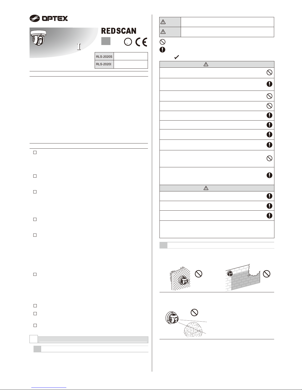
Install the product so that the detection
area is not influenced by interference
from tall grass or tree branches waving
in the wind.
Do not install or leave the product in a
location exposed to heat, vibrations or
impacts.
Do not use the product in an
environment where solvent fumes or
corrosive gases are present.
NO. 59-2408-6
INSTALLATION INSTRUCTIONS
Indoor/Outdoor model
Indoor only
RLS-2020S
Laser Scan Detector
Laser Scan Detector
RLS-2020S
RLS-2020
RLS-2020
This symbol indicates prohibition.
The specific prohibited action is provided in and/or around the figure.
This symbol requires an action or gives an instruction.
This product is not a safety component as per the machinery directive.
Do not use it for the purpose of machine safety.
Do not touch the unit base or power terminals of the product with a wet
hand (do not touch when the product is wet with rain, etc.). It may cause
electric shock.
Never attempt to disassemble or repair the product. It may cause fire or
damage to the devices.
Do not exceed the voltage or current rating specified for any of the
terminals, doing so may cause fire or damage to the devices.
Ensure the power is turned off before wiring.
Confirm the type of each terminal to ensure wiring is carried out correctly.
Whenever a commercial switching regulator is used, be sure to connect
PE (Protective Earth Terminal).
Clean and check the product periodically for safe use.
If any problem is found, do not attempt to use the product as it is.
When disposing of this product, be sure to follow the waste-disposal
regulations of the country or region where it is used.
Hold the main unit securely when you install or service it. Exercise care
not to bump the product against nearby objects or drop it inadvertently.
This product is not capable of detecting objects in the dead zone of the
laser scan.
Do not use this product for an application where it is not capable of
covering the detection area required by the task.
Please note that the product can malfunction, including producing an
irregular output and committing a detection error, if it is exposed to
unfavorable environmental conditions such as strong ambient light,
electronic noises or mechanical vibrations.
Use of controls or adjustments or performance of procedures other than
those specified herein may result in hazardous radiation exposure.
This product is intended to detect an intruder(s) and is not designed to
prevent theft, disasters or accidents. The manufacturer shall not be held
liable for any damage to user’s property resulting from theft, disasters or
accidents.
Do not use this product in environments where there may be oil mist particles
which may contaminate the window of the detector; thus causing detection errors
and possible corrosion which may lead to product failure.
There should not be any obstructs (e.g. lighting equipment, fire detectors,
cameras, poster, etc.) in the laser area.
After installation, any obstructs should not be carried/moved into the detection area.
• 20 x 20 m (65 x 65 ft.), 95 degrees detection area
• Vertical and Horizontal detection area
• Multi-angle Adjustment Shell Structure (M.A.S.S.)
• Automatic area setting function
• Advanced area setting
• 4 adjustable detection areas on IP connection
• Total 3 outputs can be assigned for analog connection
• Anti-masking, Anti-rotation, Soiling, Device trouble, Tamper output (selectable)
• Paintable housing
• Supporting multiple network protocols
RLS-2020S
• Indoor and Outdoor use
• Indoor high resolution mode
• Indoor throw-in mode
• Area selection
• Environmental disqualification circuit (DQ)
1-2
PRECAUTIONS
mini
The check mark indicates recommendation.
Caution
Warning
EN
(UL) 59-2408-4 1703-01
Failure to follow the instructions provided with this indication and
improper handling may cause death or serious injury.
Failure to follow the instructions provided with this indication and
improper handling may cause injury and/or property damage.
Install the product only on a solid
surface.
Do not install the product on an
uneven surface.
Avoid mounting near vents or devices
which cause high levels of smoke or
condensation.
Warning
Caution
SECURITY
U
L
LISTED
R
6-3 NETWORK CONFIGURATION................................................................. 10
Page 2
EN-2
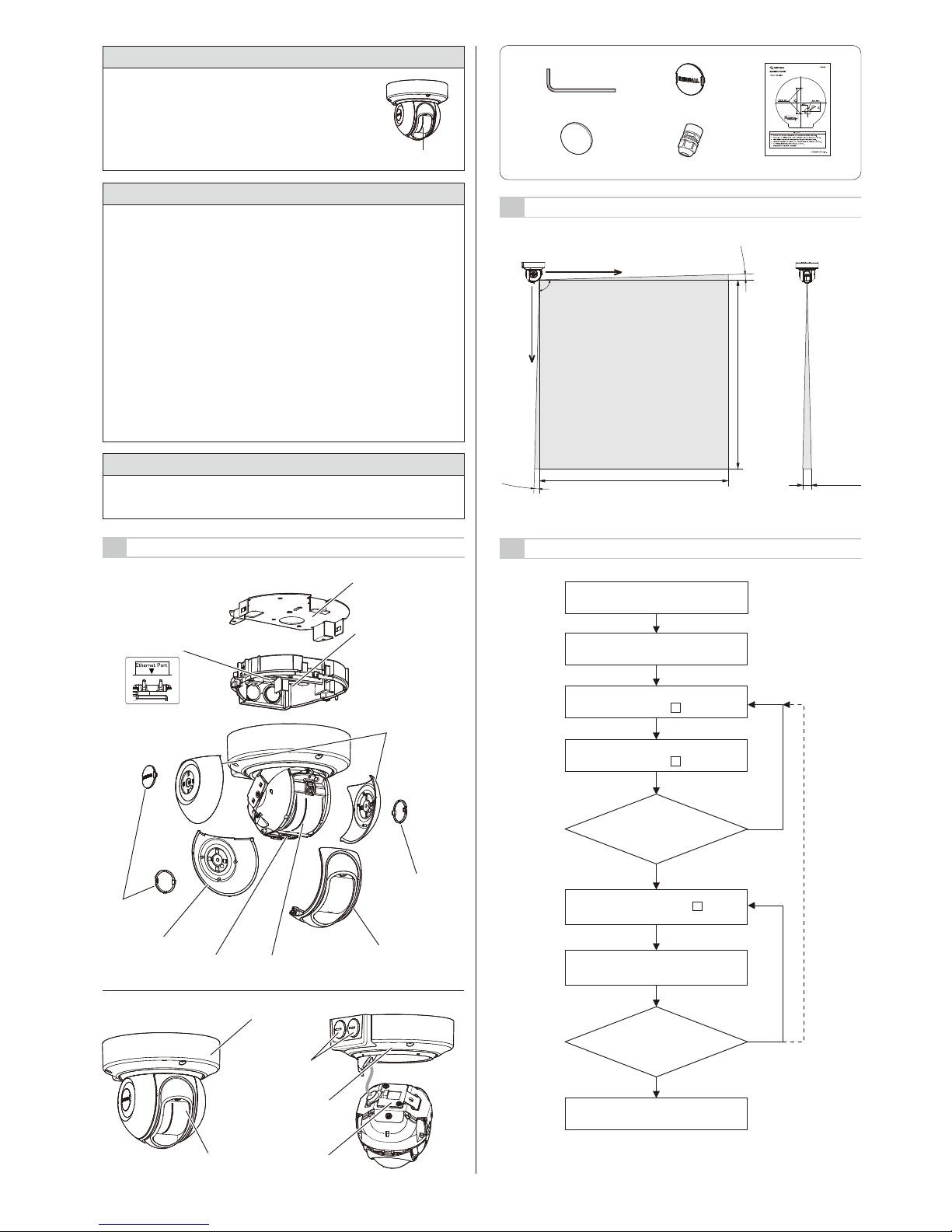
1-5
INSTALLATION WORK FLOWCHART
1-4
DETECTION AREA
1-3
PARTS IDENTIFICATION
Clean the laser window using a damp cloth.
A smeared laser window can limit the detection area due to
the reduced laser sensitivity. In addition, heavy soiling of the
window can induce detection errors.
Cleaning the Product
Laser window
This product is categorized as a Class 1 product in terms of the Safety
Standard.
Average Power : Max. 0.021 mW (AEL)
Wavelength : 905 nm
Pulse Width : 4 ns
Emission period : 35 μs
Standard : IEC 60825-1
Class 1 of the Laser Safety Standard means that the safety of laser products
belonging to this class is warranted under normal operating conditions
(reasonably predictable operating conditions). The product is marked to indicate
that it is laser equipment. No additional safety measures are necessary.
Complies with 21 CFR 1040.10 and 1040.11 except for deviations pursuant to
Laser Notice No.50, dated June 24, 2007.
Class 1 laser product
Do not expose your eyes directly to the laser beam
On Safety of Laser
Warning: This is a class A product. In a domestic environment this product may
cause radio interference in which case the user may be required to take
adequate measures. (EN 55032)
CE Statement
Walk-test and confirm
the detection area.
(Refer to 4-3)
Change the assembly option according
to the mounting type. (Refer to 2-2, 2-3)
Mounting and angle adjustment.
(Refer to 4 )
Wiring and Power On
(Refer to 5 )
Laser area confirmation
(Refer to 4-3)
Area setting (Refer to 6 )
Configuration
Completion
OK
OK
NG
NG
Choose the detection area mode and
installation location. (Refer to 2-1)
X
Y
Side view Front view
20 m max.
20 m max.
Approx.
400 mm
90°
2.5°
2.5°
Cable gland: x1
Allen key: x1 Side cover cap: x3
Wall packing: x1
Accessories >>
Paper template: x1
Base
Ethernet port
Mounting bracket
Side cover S
Side cover L
Maintenance port
Front cover
Laser window
Side
cover cap
(Accessories)
Side
cover cap
(Accessories)
Base unit
Main unit
Base cover
Wiring cover
Blanking cap
Page 3
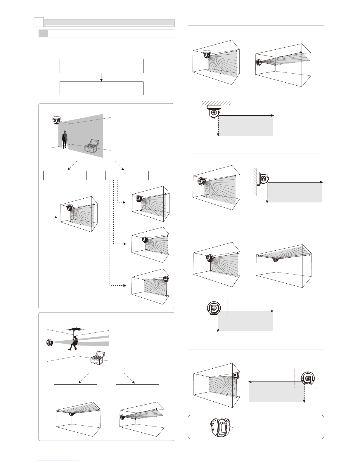
EN-3
-Type C
• Vertical area for wall mount
at the left corner
-Type D
• Vertical area for wall mount at the right corner
X
Y
Mounting surface
X
Y
Mounting surface
X
Y
Mounting surface
• Vertical area for ceiling mount
-Type A
-Type B
• Vertical area for wall mount
X
Y
Mounting surface
Caution >>
Fixing screw of
the front cover
The detection area should cover the
intruders approach.
Which detection area is appropriate,
Vertical or Horizonrtal?
Vertical Detection Area
CEILING MOUNT WALL MOUNT
Type C
Type D
Type B
Type A
Horizontal Detection Area
CEILING MOUNT WALL MOUNT
Type C
Type A
2
MOUNTING TYPE AND ASSEMBLY OPTIONS
2-1
MOUNTING TYPE
RLS-2020 has type A, B, C, and D to be installed.
Select the correct type of assembly to match the installation.
For the vertical detection area to
the mounting surface, be sure that
the fixing screw of the front cover is
placed on top.
The detector can create vertical
detection area.
Protect the asset from intruder who
across the detection area.
The detector can create horizontal
detection area.
Protect the asset from intruder who
across the detection area.
• Horizontal area for wall mount
• Horizontal area for ceiling mount
Detect!
Detect!
Page 4
EN-4
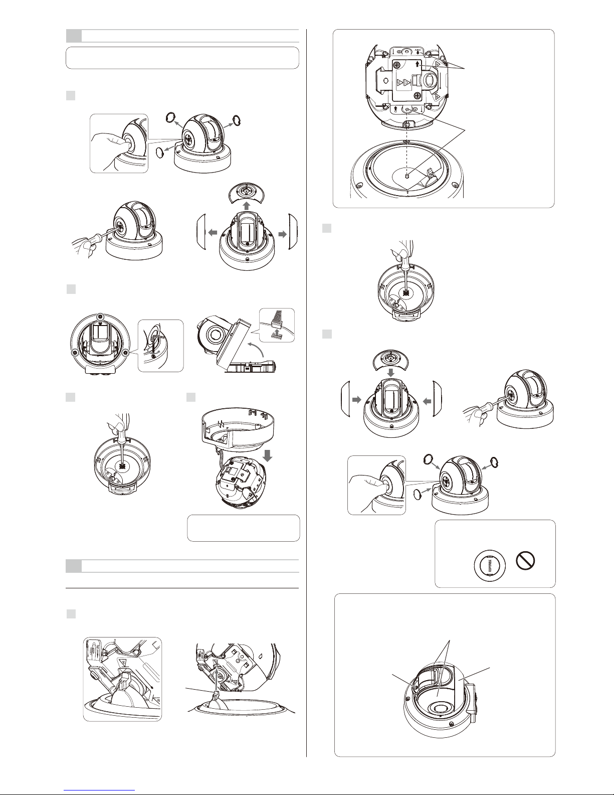
2-3
ASSEMBLY OPTIONS
Follow the procedure below to return to type A from other mounting types.
-Type A (Default)
1
Rotate the main unit and insert the hook of the base cover into the position
where the letter "A" is written on the wiring cover.
Hook
2-2
DISASSEMBLY
Disassemble the following parts in preparation.
1
Remove the side cover caps, side cover (L) and side covers (S).
2
Loosen 3 screws and remove the base.
3
Turn over the unit and remove the
screw at the center.
4
Remove the base cover.
Caution >>
Do not apply loads to the wiring.
Note >>
1.
2. 3.
Disassembling is not required to use type A. (factory default)
2
Turn over the unit and adjust the position of the screw hole, and tighten the
screw at the center.
3
Mount the side cover L, side cover S and side cover cap.
2.
1.
3.
Note >>
Mount the cover caps and the logo must
be displayed horizontally.
Note >>
1.
2.
Side cover L
Note >>
Before assembling, confirm
the arrow mark on the wiring
cover and the same with
ABC on the main unit face
each other.
Then, place the main unit
on the base unit, so as to
match the screw hole of
the main unit and the one
at the center of the base
cover as indicated.
The positions of the fixing screw and side cover are shown
below.
Fixing screw
Side cover S
Page 5

EN-5
2
-Type D
1
Loosen 2 screws and remove the wiring cover.
2
Rotate the wiring cover by 180 degrees and replace it.
1
Rotate the main unit and insert the hook of the base cover into the position
where the letter "B" is written on the wiring cover.
Note >>
2
Assemble parts just as step 2 to 3 for type A.
-Type C
1
Rotate the main unit and insert the hook of the base cover into the slot of the
wiring cover.
-Type B
Slot of the wiring cover
Hook
Then, place the main unit on
the base unit, so as to match
the screw hole of the main unit
and the one at the center of
the base cover as indicated.
Hook
3
Rotate the main unit and insert the hook of the base cover into the slot of the
wiring cover.
Slot of the wiring cover
Hook
4
Note >>
Then, place the main unit on
the base unit, so as to match
the screw hole of the main unit
and the one at the center of
the base cover as indicated.
Note >>
Note >>
Note >>
Note >>
Then, place the main unit on
the base unit, so as to match
the screw hole of the main unit
and the one at the center of
the base cover as indicated.
Side cover L
Fixing screw
The positions of the fixing screw and side cover are shown
below.
Side cover L
Fixing screw
The positions of the fixing screw and side cover are shown
below.
The positions of the fixing screw and side cover are shown
below.
Assemble parts just as step 2 to 3 for type A.
Assemble parts just as step 2 to 3 for type A.
Side cover S
Side cover S
Side cover L
Fixing screw
Side cover S
Before assembling, confirm
the arrow mark on the wiring
cover and the same with
ABC on the main unit face
each other.
Before assembling, confirm
the arrow mark on the wiring
cover and the same with
ABC on the main unit face
each other.
Before assembling, confirm
the arrow mark on the wiring
cover and the same with D
on the main unit face each
other.
Page 6

EN-6
3
BEFORE INSTALLATION
3-1
REMOVING THE FRONT COVER
Note >>
The procedure to open the front cover is required when connecting the LAN cable to
the maintenance port. (refer to 5-6)
Caution >>
Do not touch the laser window exept it’s frame.
Do not touch inside.
1
Loosen the screw on the front
cover and pull the front cover
forward with a snap.
2
Rotate the front cover at opposite
side of the screw upward and
remove the hooks (x2).
3-2
MOUNTING THE FRONT COVER
1
Snap the front cover into the main
unit.
2
Tighten the screw.
Note >>
The laser window needs to be
removed when pressing the
reset button or replacing it.
Caution >>
Be sure to turn OFF the
power supply when mounting
or removing the laser window.
Caution >>
Be sure to turn OFF the power supply when mounting
or removing the laser window.
3-3
REMOVING THE LASER WINDOW
As shown in the figure below, use the supplied allen key to put out the hook
upward in a leverage motion.
3-4
MOUNTING THE LASER WINDOW
As shown in the figure below, insert the foot of the laser window until it clicks.
3-5
WIRING CABLE ENTRY
Use a screwdriver to open a knockout.
2 wiring holes
Make a slit with a cutter.
-Wiring hole on the back side
Caution >>
Be sure to open a knockout to the
downward direction.
When performing wiring on the
back side, Apply the supplied
packing on the depression on
the back side of base.
Note >>
1. Loosen the screw.
2. Pull the cover
forward.
Tighten the screw.
1. Use the allen key
to remove the
hook.
2. Open it slightly
and then pull
out upward.
-Wiring hole on the side
Remove the blanking caps of the wiring holes on the side using a tool such as a
coin.
1.
2.
1 knockout
1. Insert the hook.
2. Push the unit until it clicks.
Pass the wiring through the slit of
the packing.
Page 7

EN-7
4-2
ANGLE ADJUSTMENT
4-3
LASER AREA CONFIRMATION
It is recommended that the optional Laser Area Checker(LAC-1) is used to
confirm the location of the laser plane.
Check that the laser beams are targeted to the desired areas.
Tips: Two units of LAC-1 (option) can make it easier to confirm
the detection area.
1
Slightly loosen 3 fixing screws.
2
Use the laser area checker to adjust the angle and then tighten
3 fixing screws.
7
Insert the base hook in to the base cover and ensure that the fixing screw
does not jam against the cover.
Close the base cover, and then tighten the 3 screws to fix it.
-Vertical Detection Area
-Horizontal Detection Area
1
Adjust the detector's angle so that
the laser beam hits the farthest
position of the required area and
just the bottom of the detector.
2
Check that the entire area is
covered properly with laser area
checker (option: LAC-1).
Note >>
For detailed instructions refer to the
LAC-1 instruction manual.
Note >>
Align the markings of the base unit and main unit to be the guideline
for the direction of the detection area.
1.
2.
3.
Approx. 4° virtically and horizontally
4
INSTALLATION AND ANGLE ADJUSTMENT
4-1
WALL OR CEILING MOUNTED
Caution >>
Do not supply the power for this unit during wiring.
1
Remove the mounting bracket
from the base, using a tool such
as flathead screwdriver.
Methods for ceiling mounting and wall mounting are the same.
2
Place the supplied paper template
on the mounting surface and open
2 mounting holes.
3
Mount the mounting bracket to the
mounting surface.
Screws to fix the mounting bracket
are not included.
4
Attach the base into the mounting
bracket until it clicks.
5
Perform wiring. (See 5-1.)
6
Connect the base and main unit
with wiring. When the LED at the
side of the relay connecter is ON,
turn OFF the power supply before
connecting them.
Relay connector
Caution >>
The LAN cable with the cover on cannot passes through the cable gland.
Be sure to remove the cover before use.
Caution >>
Do not install the cable gland upward than horizontal line. Doing so may reduce the
waterproof performance.
3-6
INSTALLING NETWORK CABLE
1
Disassemble the cable gland.
2
Pass the Ethernet plug with the correct order and direction. Put the seal from
the side.
Seal
Sensor side
±180°horizontally
Note >>
Pull the base to make sure that the
base is completely attached.
Note >>
Make sure that the arrow points upward
when mounting the detector on the wall.
180° 180°
Note >>
3.5 mm max.
Φ9.5 mm max.
4 mm
/ No.8
Page 8

EN-8
5-2
PROGRAMMABLE SIGNAL OUTPUT
5-3
PROGRAMMABLE SIGNAL INPUT (RLS-2020S only)
The three output terminals can be configured as NO/NC. They
are however fixed as open when the unit is not energized.
The outputs are programmable from options below.
Alarms
• Master alarm (MO)
• Zone alarm
(A1, A2, B1, B2)
Troubles
• Anti-masking (AM)
• Anti-rotation (AR)
• Soiling (SO)
• Environmental disqualification
(DQ)
• Device trouble (TR)
• Tamper output (TA)
5
PARTS LAYOUT INSIDE AND THEIR FUNCTIONS
5-1
WIRING
Inside the base
The length of the power wire
must be less than the figures
listed below.
Stripping length
m (ft)
Wire size
12VDC 24VDC
AWG18
(0.83 mm
2
)
AWG20
(0.52 mm
2
)
30
(100)
AWG16
(1.31 mm
2
)
Strip the cover of the
wiring about 9 mm.
9 mm
Cable
PoE (IEEE802.3 standard)
Cat5e or
above
50
(160)
80
(260)
790
(2590)
1260
(4130)
2000
(6560)
100
(320)
Relay connector
Signal input
(RLS-2020S only)
Signal output 3
Signal output 2
Signal output 1Power supply input
Wall tamper input
Ethernet port (PoE)
5-9
LED INDICATOR
Stand-by
Alarm
Anti-masking
Anti-rotation
Soiling
Environmental
disqualification
(DQ)
Red
Yellow
Green
Blink Light OFF
Detector condition
Warm-up
(apprpx. 60 s)
LED
*
* According to alarm status.
Motor error
Hardware error
Over heat
Others
(not fixed the laser
window properly, etc.)
Trouble condition
LED
Green blinks once. Yellow blinks once.
Green blinks once. Yellow blinks twice.
Green blinks once. Yellow blinks 3 times.
Green blinks once. Yellow blinks 4 times.
x 2
x 3
x 4
Green blinks once. Red blinks once.
Green blinks once. Red blinks twice.
x 2
Green blinks once. Red blinks 3 times.
x 3
Green blinks once. Red blinks 4 times.
x 4
REPEAT
REPEAT
REPEAT
REPEAT
REPEAT
REPEAT
REPEAT
REPEAT
Note >>
Some PoE netwok switches have a limit for wattage. Connect the detectors
to PoE network switches without exceeding the limit referring to their
instructions.
5-8
INITIALIZATION TO FACTORY DEFAULT
5-7
POWERING ON
Enter the DC power to the power supply input terminal.
Or, connect PoE power supply equipment to the ethernet port (PoE)
.
After power on, all the indicators are turned on for approx. 60 seconds and then
the status and alarm indicators are turned off.
During this period, REDSCAN mini itself performs initial settings.
Reset button
1. Turn Off the power supply. Remove
the front cover and laser window.
(refer to 3-1,3-3)
2.
Power On while pressing the reset button.
3. All LEDs turn On. Red LED turns Off
after 50 sec, and green LED turns Off
after 2 sec. And then, release the reset
button.
Yellow LED turns off after 3 sec.
4. Turn Off the power supply.
Attach the laser window and the front
cover. Then, Power On.
* As for wiring for UL application, refer to UL statement on the end of page 11.
5-4
ETHERNET PORT (PoE)
5-5
MAINTENANCE SECTION
The Ethernet port inside the base is for constant
connection. PoE is supported.
LED indicator Maintenance port
Default
IP address : 192.168.0.126
Subnet mask : 255.255.255.0
Default gateway : 192.168.0.1
Note >>
At a maintenance port, Use a light LAN
cable for indoor use. (Do not use the
heavy LAN cable for exterior use.)
This port is for maintenance purpose.
After maintenance, re-assemble the front
cover.
Note >>
Do not use the same subnet for the main Ethernet port and the Maintenance port.
Programmable input can be used for the following functions.
・
Signal Output 1 for confirmation of the function
・
Signal Output 2 for confirmation of the function
・
Signal Output 3 for confirmation of the function
When the signal input is closed, the signal output (1 to 3)
responds as change the status of output. It can be used for
confirmation that the detector is operated properly.
・ Switching to Next Masking / Allocating file
When the signal input is closed, the unit changes Masking/Area
Allocation pattern files. e.g. File 1 to File 2, File 2 to File 3, File 3
to File 4 and File 4 to File 1... It can be used for switching
Masking/Allocation pattern remotely without REDSCAN Manager.
・Area Set
When the signal input is closed, Area set is started.
It can be used for re-creating the detection area without
REDSCAN Manager.
For settings this function, the dedicated software, REDSCAN Manager is required.
If signal input is closed shorter time than the judgement time (Default 1 sec.,
adjustable range 1 to 10 sec), it will be ignored.
5-6
MAINTENANCE PORT
The Ethernet port on the maintenance section is
connected only for initial set-up. Do not use it for
constant connection.
Default
IP address : 192.168.1.126
Subnet mask : 255.255.255.0
Note >>
Do not use the same subnet for the main Ethernet port and the Maintenance port.
*Refer to UL statement
on the end of page11
Page 9

EN-9
The following setting items can be configured. Use pull-down menu or enter a
value. Items that are unavailable for setting are grayed out, depending on a model
or mode.
6-2
DETECTION CONFIGURATION
6-1
OVERVIEW
There are two options to setup the unit with WEB browser for simple setting and
optional setup software, Redscan Manager software for advanced configuration.
This instructions mention for the setting with WEB browser. For setting with
Redscan Manager, please refer to the help of the software.
A web browser can be used to configure the Redscan mini settings.
The ethernet port on the base unit and the maintenance port on the main unit can
be used for configuration.
The main port is for the operation and settings, the maintenance port is for
settings by web browser or REDSCAN Manager.
Recommend web browser: Chrome.
< Default setting >
Main Ethernet port IP address : 192.168.0.126
Subnet Mask : 255.255.255.0
Default gateway : 192.168.0.1
Maintenance port IP address : 192.168.1.126
Subnet Mask : 255.255.255.0
MTU : 1500
ID : REDSCAN
Password : OPTEX
When connected, the start page appears:
Described below are menu displayed on the screen left:
• Output/Input Status
Indicates statuses of the device output/input, REDWALL Event Code and
Soiling ratio of laser window. Outputs can be triggered manually.
.
• Detection Configuration
Configures detection settings.
• Network Configuration
Configures network settings.
• Authentication
Configures user ID and password.
• Maintenance
Shows MAC address and licences. Updates firmware and reboots the unit.
6
SETTING
• Area Set
After installation and angle adjustment of the laser beam, press this button before
starting the setting adjustment. The unit learns background and adjusts detection
area. No human body must enter the area to be configured as a detection area.
Otherwise the area may not be configured properly.
• Area Set Information
To indicate the date of area setting.
• Save Config.
Transfers and saves the setting configured on the browser. Press this button
after configuring the setting.
• Detection Mode
Four modes are available:
[ Indoor mode ] (RLS-2020I and RLS-2020S)
For general indoor applications. (Default)
Can make vertical detection area or horizontal detection area according to the
mounting direction.
[ Outdoor mode ] (RLS-2020S only)
This option can be selected for general outdoor applications.
In this mode, the special algorism works to reduce false alarms by weather
conditions (e.g. rain, snow and fog).
In order to reduce the false alarms under harsh environment, the environmental
resistance function can be set as enable.
[ Indoor high resolution mode ] (RLS-2020S only)
By increasing detection resolution, the unit can detect small object at longer
distance. In regular indoor mode, the resolution is 0.25 degree.
In this high resolution mode, it gets 0.125 degree.
Thus, the same small size object can be detected at the double distance. But,
fastest response time can be within 100 ms in this mode, the unit may not detect
fast movement object. This mode shall be use for only indoor application.
[ Indoor throw-in mode ] (RLS-2020S only)
This mode can work to detect the object which is thrown into the detection area.
Response time is the minimum within 25ms.
This mode shall be use for only indoor application.
• Detection Area
Three options are available:
[ Horizontal ]
Creating a detection area in parallel with the ground, such as ceiling protection.
[ Vertical ]
Creating a detection area perpendicular to the ground, such as wall protection.
[ Auto ] (Default)
For automatic selection by a sensor direction.
• Environmental Resistance (RLS-2020S only)
Erroneous reports under a bad environment such as a fog can be reduced when
outdoor mode is selected.
[ Disable ]
Configure this when a report without a delay is required for an application of
PTZ camera linkage.
This setting may cause an erroneous report under a bad environment such as a
fog or snow.
[ Enable ] (Default)
False alarm due to a fog or snow can be reduced with balanced high detection
ability.
[ Enhanced ]
Reduction of erroneous reports due to a fog or snow can be maximized. It may
result in a longer response time.
In addition, detection may fail under certain environments.
Normal Indoor high resolution
0.25 degree 0.125 degree
*Refer to UL statement on the end of page 11.
• Network Options
Configures network options.
REDSCAN mini Configuration Page RLS-2020 Version. 2.1.0 (07 aug2018)
Output/Input
Status
Detection
Configuration
Network
Configuration
Network Options
Authentication
Maintenance
Area Set
Area Set
Information
Save Config
REDSCAN mini Configuration
Detection Mode
Detection Area
Environmental Resistance
Sensitivity
Minimum Target Size
(Width)
Target Height for Vertival
Area
* Ignoring Area from Ground
Non-Detection Zone for
Vertical Area
* Ignoring Area from Ceiling
Detection Range 1
* For vertical detection area, input “detection length”
* For horizontal detection area, input “detection width”
Detection Range 2
* For vertical detection area, input “detection length”
* For horizontal detection area, input “detection width”
Offset
Length mm, m inch, ft.
Indoor mode
Auto
Disable
H M L Custom
150 msec. (75-9 000 000)
150 mm (10-1 000)
250 mm (1-1 000)
0.1 m (0-20)
20 m (1-20)
20 m (1-20)
100 mm (0-1 000)
REDSCAN mini Configuration Page RLS-2020 Version. 2.1.0 (07 aug2018)
Output/Input
Status
Detection
Configuration
Network
Configuration
Network Options
Authentication
Maintenance
IP Communication
<REDWALL Event Code (R.E.C.)>
Soiling Ratio of Laser Window
0%
Analog Connection <Terminal
Status>
Input
Output1Output2Output3
(S Model Only)
Duration Activating Terminal
sec.
5 (1- Output1 Output2 Output3
1 800)
Page 10

EN-10
IDs and passwords can be changed.
• Change authentication
[ New user ID ] Default : REDSCAN
[ New password ] Default : OPTEX
To reflect the setting, press [Save Config] button to send and save the setting to
the detector.
When losing the ID and password, the detector must be initialized.
(Refer to 5-8 Initialization to factory default.)
6-5
AUTHENTICATION
The unit's main communication port can be configured.
• Network Configuration of Main Ethernet Port
Configuration Type: Default “STATIC”
Select “STATIC” or “DHCP”
IP address: Default 192.168.0.126
Subnet Mask : Default 255.255.255.0
Default gateway : Default 192.168.0.1
MTU : 1500
• Network Configuration of Maintenance Port
IP address : Default 192.168.1.126
Subnet Mask : Default 255.255.255.0
• Event Code Configuration
[ Transmission Mode ] : Can be select from the following option
UDP-Broadcast, UDP-Unicast, TCP, UDP-Broadcast & TCP and
UDP-Unicast & TCP
[ Heartbeat for Device Monitoring ] : Can transmit a device monitoring
code to external devices for alive monitoring ( Default : Off )
[ Destination IP Address and Port number ]
UDP IP Address : Default 192.168.0.1
Port Number : Default 1234
TCP IP Address : Default 192.168.0.1
Port Number : Default 1234
6-3
NETWORK CONFIGURATION
Note >>
For further setting changes (Detection area shape, Area selection and Input/Ouputs
configuration), the optional setup software, Redscan Manager Software can be used.
• Target height for vertical area : Default 250 mm (10 inch.)
Enter 1 to 1,000 mm (0.04 to 40 inch)
• Non-Detection zone for vertical area
Default : Indoor / Indoor high resolution / Indoor throw-in mode 0.1m (0.3 ft),
Outdoor mode 1.5 m (5 ft)
In a vertical detection area, protruding objects on the ceiling can be excluded from the
detection area by disabling the upper part of the area by a specified distance.
Enter a desired length to disable.
The width is narrowed by a specified distance from the front direction from the main unit.
• Detection Range 1 Default : 20 m (65 ft.), 1 to 20 m (3.3 to 65 ft.)
For a vertical detection area, enter a length of an area to be detected. For a
horizontal detection area, enter a width of an area to be detected.
• Detection Range 2 Default : 20 m (65 ft.), 1 to 20 m (3.3 to 65 ft.)
For a vertical detection area, enter a height of an area to be detected. For a
horizontal detection area, enter a depth of an area to be detected.
• Offset Default : 100 mm (4 inch.), 0 to 1,000 mm (0 to 39 inch.)
For a vertical detection area, reflection from the ground or floor can generate noise for
the detector. Also, plants and small animals can cause a false alarm.
An offset can exclude a detect
ion area by a specified distance from the ground or floor.
• Minimum Target Size (Width)
Enter a width of an object to be detected.
(Default value depends on detection mode)
[ Indoor mode ] (Default: 150 mm (6 inch))
Enter 10 to 1,000 mm (0.4 to 40 inch)
[ Outdoor mode ] (Default: 250 mm (10 inch))
Enter 10 to 1,000 mm (0.4 to 40 inch)
[ Indoor high resolution mode ] (Default: 50 mm (2 inch))
Enter 10 to 1,000 mm (0.4 to 40 inch)
[ Indoor throw-in mode ] (Default: 150 mm (6 inch))
Enter 10 to 1,000 mm (0.4 to 40 inch)
Detectable range based on a target size
When configuring a target size smaller than 200 mm ( 8 inch), a distance to detect
an object with the size gets shorter.
• Sensitivity
Can be set from the options, H (High), M (Medium), L (Low), or Custom (Enter
required response time).
[ Indoor mode ] (Default M: 150 ms, H: 75ms, L: 500 ms)
Custom: Can be set from 75 to 900,000 ms (15 min.)
[ Outdoor mode ] (Default M: 150 ms, H: 75 ms, L: 500 ms)
Custom: Can be set from 75 to 900,000 ms (15 min.)
[ Indoor high resolution mode ] (Default M: 200 ms, H: 100 ms, L: 500 ms)
Custom: Can be set 100 to 900,000 ms (15 min.)
[ Indoor throw-in mode ]
Fixed to 0 ms. every scan report alarm.
Indoor/Outdoor/Indor throw-in mode
Target size
25 mm (1 in.)
50 mm (2 in.)
100 mm (4 in.)
150 mm (6 in.)
200 mm (8 in.)
300 mm (12 in.)
Black plate
-
4.0 m (13 ft.)
7.8 m (26 ft.)
11.4 m (37 ft.)
15.0 m (49 ft.)
21.0 m (69 ft.)
White plate
-
5.0 m (16 ft.)
8.8 m (29 ft.)
12.6 m (41 ft.)
16.4 m (54 ft.)
23.4 m (77 ft.)
Indoor high resolution mode
Target size
25 mm (1 in.)
50 mm (2 in.)
100 mm (4 in.)
150 mm (6 in.)
200 mm (8 in.)
300 mm (12 in.)
Black plate
-
4.4 m (14 ft.)
6.9 m (23 ft.)
12.6 m (41 ft.)
17.6 m (58 ft.)
22.0 m (72 ft.)
White plate
-
5.4 m (18 ft.)
8.9 m (29 ft.)
15.8 m (52 ft.)
22.0 m (72 ft.)
28.0 m (92 ft.)
* Reflectivity of Black plate: 10%
* Reflectivity of White plate: 90%
* Detectable range depends on the reflectivity of target and its shape.
Need to confirm the detectable range with actual target at the installation location.
[ Connection test ] : Can confirm the connection to the destination IP address
and port number.
You can configure multiple advanced network protocol options.
Consult your network system administrator when you use these options.
•
Web Server Configuration
Configure Web Server details.
• SNMPConfiguration
Configure SNMP details.
• Discovery
Enable/Disable WsDiscovery.
• DNS Configuration
Configure DNS details.
6-4
NETWORK OPTIONS
REDSCAN mini Configuration Page RLS-2020 Version. 2.1.0 (07 aug2018)
Output/Input
Status
Detection
Configuration
Network
Configuration
Network Options
Authentication
Maintenance
Save Config
Network Configuration of Main Ethernet Port
Configuration Type
IP Address
Subnet Mask
Default Gateway
MTU
Indoor mode
192.168.0.126
255.255.255.0
192.168.0.1
1500 (1000-1500)
Network Configuration of Maintenance Port
IP Address
Subnet Mask
192.168.0.126
255.255.255.0
UDP Broadcast
Event Code Configuration
Transmission Mode
Heartbeat for Device
Monitoring
Detector ID
Use an arbitrary number
Detector ID
UDP
Destination IP Address
Destination Port Number
TCP
Destination IP Address
Destination Port Number
000 (000-999)
192.168.0.1
1234
Connection Test
192.168.0.1
1234
Connection Test
REDSCAN mini Configuration Page RLS-2020 Version. 2.1.0 (07 aug2018)
Output/Input
Status
Detection
Configuration
Network
Configuration
Network Options
Authentication
Maintenance
Save Config
Web Server Configuration
Web Server Protocol
HTTP Port
HTTPS Port
Current Certification
HTTP
80 (0-65535)
443 (0-65535)
RLS-2020
Show Detail Information Show CSR Information
Select CRT Install CRT Create Self-certification
SNMP Configuration
Enable SNMPv1
Enable SNMPv2
Enable SNMPv3
Changes SNMPv3 Authorization
Authorization Method
Encryption
New User ID
New Password
New Password Again
MD5
DES
(Max 32 characters)
(8-12 characters)
(8-12 characters)
Discovery
Enable WsDiscovery
DNS Configuration
DNS Server Address
Domain Name
Primary DNS Server
Secondary DNS Server
STATIC
(Max 243 characters)
0.0.0.0
0.0.0.0
REDSCAN mini Configuration Page RLS-2020 Version. 2.1.0 (07 aug2018)
Output/Input
Status
Detection
Configuration
Network
Configuration
Network Options
Authentication
Maintenance
Save Config
Change Authentication
New User ID
New Password
New Password Again
Valid characters. A-Z/a-z/0-9 (Max 20 characters)
Valid characters. A-Z/a-z/0-9 (Max 20 characters)
Page 11

• Update software
Can update the firmware of the unit. If necessary, click Choose File button to
select the firmware file, and push Update button.
• MAC address
Shows MAC addresses for Main Ethernet Port and Maintenance Port.
• License
Click to show licenses of free open source software.
• Reboot
Can reboot the unit.
6-6
MAINTENANCE
EN-11
7
DIMENSIONS
7-1
DIMENSIONS
8
SPECIFICATIONS
8-1
SPECIFICATIONS
* Specifications and design are subject to change without prior notice.
Model
Installation location
Detection method
Indoor Indoor/Outdoor
Infrared Laser Scan
Laser protection class Class 1
Power input 10.5-30 VDC, PoE (IEEE 802.3af/at compliant)
Ceiling mount, Wall mount, Tripod mount,
Pole mount (Option), Recess mount (Option)
20 ×20 m (approx. 65×65 ft.), 95 degree
Current draw
Detection area
500 mA max. (12 VDC), 250 mA max. (24 VDC),
6 W max. (PoE)
Mounting method
Communication port
Detection range
Radius 1 to 21 m (approx. 3.3 to 68 ft.) at 10% reflectivity
Detection resolution/
Response time
Ethernet RJ-45
10BASE-T/100BASE-TX (Auto negotiation)
Protocol
Output
TCP/IP, UDP/IP, DHCP, DNS, HTTP, HTTPS,
FTP, SNMPv1/v2c/v3, ICMP, ARP
Input
Approx. 2 second delay timer
1 Non-voltage contact input
Alarm period
-40°C to 50°C degree
(-40°F to 122°F degree)
Operating temperature
IP66IP rating
146 × 160 × 160 mm (5.8 ×6.3 ×6.3 inch)Dimensions (H×W×D)
1.0 kg (2.2 Lbs)Weight
0.25 degrees
/ within 75 ms to 1 minute
0.25 degrees
/ within 25 ms to 1 minute
0.125 degrees
/ within 100 ms to 1 minute
(for indoor high resolution mode)
Mounting height
(Vertical mode)
2 m (6.7 ft.) or higher
Indoor: 2 m (6.7 ft.) or higher
Outdoor: 4 m (13 ft.) or higher
(Recommended)
Unit: mm (inch)
83.5
(3.29)
(Single Gang Box)
Φ160
(6.3)
160
(6.3)
146
(5.7)
1/4 -20UNC
84.9
(3.34)
(4’ Electrical Box)
84.9
(3.34)
3 outputs, 28 VDC 0.2 A
max. N.O./N.C. Selectable
(3 from Master alarm, Zone
alarm, Trouble, Tamper)
3 outputs, 28 VDC 0.2 A
max. N.O./N.C. Selectable
(3 from Master alarm, Zone
alarm, Trouble, Tamper, DQ)
< Purpose >
RLS-2020 generates original ASCII event codes which can be used by an NVR or
VMS software to control PTZ cameras and other devices.
< Communication methods >
REDWALL EVENT CODE can be sent to the assigned port using UDP or TCP
protocol. The default port number is “1234”.
< Code format >
6-7
REDWALL EVENT CODE (R.E.C.)
ID number of the RLS-2020 unit consist 6 bytes as follows.
RLS + 3 bytes number (Default number is the last group of the host IP address.)
“RLS126 MO A1 AA CC DQ AR AM TR SO TA”
ID number of
the RLS-2020
Y1
Master
alarm
Y2
Latest
alarm
Y3
Multiple
alarm
Y4
Multiple
alarm
......... Y10
Tamper
Position
Command
Description
Y1 MO/CL
Y2
A1/A2
/B1/B2
Latest alarm.
Y3
AA-BB,
EA-EB,AL
It shows detected areas by 11 patterns. *
Y4 CC
Y10 TA/ta/DM
Tamper circuit activates/ Tamper circuit status is restored
/ “Heart beats” for device monitoring.
Y8 TR/tr Trouble condition / Trouble condition restored.
Y9 SO/so
Soiling on the laser window (Self checking function) /
Soiling on the laser window status is restored.
Y7 AM/am
Anti-masking function activates / Anti-masking status is restored.
Y5 DQ/dq
Environmental disqualification circuit activates
/ Environmental disqualification circuit status is restored.
Y6 AR/ar
Anti-rotation function activates / Anti-rotation status is resotred.
R.E.C.
AA
BB
BA
Ba
bA
ba
B2 B1 A1 A2
R.E.C.
EA
Ea
Eb
EB
AL
B2 B1 A1 A2
* Multiple alarm
Any alarm zone are triggered, Master alarm code, "MO"
code is generated. And, "CL" code is generated 10
seconds after master alarm was cleared.
The time can be changed by setting software.
Multiple alarm.
CC means that there are multiple detected areas.
Note >>
Contact to OPTEX to get more detailed specifications of REDWALL Event Code.
* Refer to UL statement on
the end of page 11.
-40°C to 60°C degree
(-40°F to 140°F degree)
* Refer to UL statement on
the end of page 11.
Update
REDSCAN mini Configuration Page RLS-2020 Version. 2.1.0 (07 aug2018)
Output/Input
Status
Detection
Configuration
Network
Configuration
Network Options
Authentication
Maintenance
Update Software
Select File Not Selected
MAC Address
Main Ethernet Port 00:1f:d1:1d:00:b3
Maintenance Port 00:1f:d1:1d:00:b4
License
Licence
Reboot
Reboot
Show License
Page 12

EN-12
Model/ Name
Place
Serial No.
Date
IP address/
Subnet mask/
Default gateway
Output 1
Output 2
Output 3
Input setting
Mode/
Parameter/
Others
< MEMO >
OPTEX INC./AMERICAS HQ (U.S.)
URL: www.optexamerica.com
OPTEX (EUROPE) LTD./EMEA HQ (U.K.)
URL: www.optex-europe.co m
OPTEX TECHNOLOGIES B.V.
(The Netherlands)
URL: www.optex.eu
OPTEX SECURITY SAS (France)
URL: www.optex-security.com
OPTEX SECURITY Sp.z o.o. (Poland)
URL: www.optex.com.pl
OPTEX PINNACLE INDIA,
PVT., LTD. (India)
URL: www.optex.net/in/en/sec
OPTEX KOREA CO.,LTD. (Korea)
URL: www.optexkorea.com
OPTEX (DONGGUAN) CO.,LTD.
SHANGHAI OFFICE (China)
URL: www.optexchina.com
OPTEX (Thailand) CO., LTD. (Thailand)
URL: www.optex.net/th/th
Copyri ght (C) 2018 OPTEX CO.,LTD.
OPTEX CO., LTD. (JAPAN)
URL: www.optex.net
■ EU contact information
Manufa cturer:
OPTE X CO., LTD.
5- 8-12 Ogoto, Ot su, Shiga ,
520- 0101 JAPAN
Author ised re prese ntative i n Europ e:
OPTE X (EUROPE) LTD./EME A HEADQUART ERS
Unit 13, Cord wallis Par k, Clivem ont Road,
Maiden head Berks hire, SL6 7BU U. K.
Remove the side cover cap, side cover L and side
cover Ss. (refer to 2-2 1 )
Remove the base cover. (refer to 2-2 2 3 4 )
Remove the front cover. (refer to 3-1)
Paint the following parts. (refer to marks as follows)
Use the suitable paint for poly-carbonate resin.
Note >>
Do not paint the front cover, the laser window or the base unit.
Painting the RLS-2020 S a dark color could raise the internal
temperature and cause a malfunction.
Painting should be avoided if there is any possibility that
the unit would be exposed to direct sunlight.
9
APPENDIX
9-1
REPAINTING
1
2
3
4
Note >>
Be careful not to lose the removed washer.
1.
2.
3.
8-2
OPTIONS
LAC-1 : Laser area checker
RLS-PB : Pole mounting bracket
RLS-RB : Recessed mount kit
RLS-LW : REDSCAN mini laser window
- In case of using DC power supply
UL required the main unit to be connected to a UL listed PoE injector or switch
and the PoE must be connected to a UL listed (UTRZ) UPS with output rating of
100-240 VAC, 1.0 A and 24 hours standby.
UL Statement
- For UL Listed installation applications
The relay outputs shall be connected to a compatible UL Listed control panel.
The equipment shall be installed in accordance with the National Electrical Code
NFPA 70.
- UL testing was conduted at temperature range of
0°C to 49°C for RLS-2020I, and -35°C to 66°C for RLS-2020S.
UL required the main unit to be connected to a UL listed power supply Class 2,
capable of providing a norminal input of 10.5-30 VDC 500 mA and battery standby
time of 4 hours.
- In case of using PoE injector or switch for power supply
UL testing was conducted with product powered from the following Listed POE:
Manufacturer: PHIHONG, Model: POE36U-1AT-R, Input: 100-240 VAC, 1.0 A, Output: 56 V - 0.6 A
UL approved the PoE connection as supplemental.
The PoE cannot be used to monitor the device.
- UL approved indoor modeandoutdoormodeonly.
Indoor high resolution mode and Indoor throw-in mode has not evaluated by UL.
The signal input cannot be connected to alarm output to reduce the risk of
false alarm.
EN 50131-1 Grades and Environmental Class:
Security Grade 3, Environment ClassII TS50131-2-11
 Loading...