

Optex REDBEAM, REDBEAM RBM-60QN-IP, REDBEAM RBM-200QN-IP, REDBEAM RBM-100QN-IP Wiring Diagram
Page 1

No.59-1968-0
WIRING DIAGRAM
NETWORK PHOTOELECTRIC DETECTOR
NETWORK PHOTOELECTRIC DETECTOR
™
™
MODEL
RBM-60QN-IP
REDBEAM series
REDBEAM series
RBM-100QN-IP
RBM-200QN-IP
BEFORE YOUR OPERATION
1
• Be sure to thoroughly read the instruction manuals of each product before performing wiring.
• The SIP mounting plate for Gang Box, Gasket sheet for Gang Box, and No. 6-32 UNC screws (5/8 inch) (6 pcs) that are described in PIE-1
Manual are not included in this product as they are not required.
• Up to two detectors can be connected to a PIE-1. (Wire size: at least AWG26 (0.13 mm
ASSEMBLY
2
Step 2
Pass the LAN cable
or the external cable
through the grooves
as shown below.
Step 1
(1) Open the knockout hole (upper or lower)
of the back box.
Upper Lower
2
), wire length: 2.5 m (8.2 ft.) max.)
(2) Connect the couduit to the knockout
hole of the back box.
ø 21mm (0.84 inch) hole diameter
Detection range
60m/200ft.
100m/
350ft.
002 m/650ft.
Refer to
Step 3
(2)
(1)
(3)
Step 1
Back box
PIE-1
(1) Plug the alarm 10-pin cable to PIE-1.
(2) Plug the power 2-pin cable to PIE-1.
Use the 24VDC connector.
(3) Set the Selector switch of PIE-1.
(4)
(4) Plug the CAT5e cable to the
Ethernet connector for PoE of PIE-1.
(5) Place PIE-1 into the back box.
Sponge
Note >>
・Run the cables so that
they are not pinched
between the chassis
and back box.
Banding band
Wiring notch
Chassis
Main unit
Step 4
(1) Mount the sponge.
(2) Mount the chassis.
(3) Mount the main unit.
(4) Wire the sensor.
(5)
Connect the alarm 6-pin and power 2-pin cables.
(6) Perform optical adjustment.
(7) Mount the cover.
Cover
Caution
Be sure to connect the connector after
cutting all the unnecessary wires.
-1-
Page 2
3
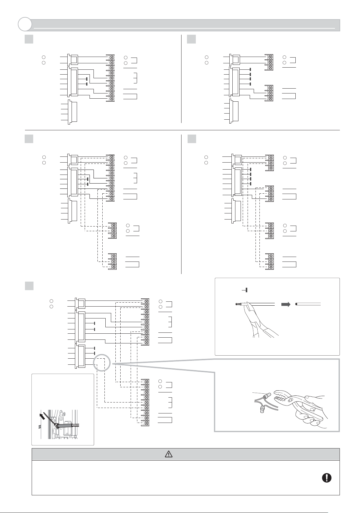
WIRING
RECEIVER ONLY
1
<Receiver>
POWER
OUTPUT
+ (Red)
-
(Black)
24VDC
(Orange)
(Orange)
(Yellow)
(Yellow)
(Green)
(Green)
(Blue)
(Blue)
(Purple)
(Purple)
TRANSMITTER AND RECEIVER
3
<Receiver>
POWER
OUTPUT
24VDC
+ (Red)
-
(Black)
(Orange)
(Orange)
(Yellow)
(Yellow)
(Green)
(Green)
(Blue)
(Blue)
(Purple)
(Purple)
<Transmitter>
(1) +
-
(2)
(3)
(4) N.O.
(5) N.C.
6) COM.
(
(7)
(8)
(9)
+
(1)
-
(2)
(3)
(4) N.O.
(5) N.C.
6
) COM.
(
(7)
(8)
(9)
(1)
(2)
(3)
POWER INPUT
10.5-30VDC
SPARE
ALARM OUTPUT
SPARE
TAMPER OUTPUT
(N.C.)
POWER INPUT
10.5-30VDC
SPARE
ALARM OUTPUT
SPARE
TAMPER OUTPUT
(N.C.)
+
POWER INPUT
10.5-30VDC
SPARE
TRANSMITTER ONLY
2
<Transmitter>
POWER
OUTPUT
24VDC
4
(Red)
+
(Black)
-
(Orange)
(Orange)
(Yellow)
(Yellow)
(Green)
(Green)
(Blue)
(Blue)
(Purple)
(Purple)
TRANSMITTER AND TRANSMITTER
(1)
+
-
(2)
(3)
(7)
(8)
(9)
<Transmitter>
POWER
OUTPUT
24VDC
(Red)
+
(Black)
-
(Orange)
(Orange)
(Yellow)
(Yellow)
(Green)
(Green)
(Blue)
(Blue)
(Purple)
(Purple)
(1)
+
(2)
-
(3)
(7)
(8)
(9)
<Transmitter>
(1)
+
(2)
-
(3)
POWER INPUT
10.5-30VDC
SPARE
SPARE
TAMPER OUTPUT
(N.C.)
POWER INPUT
10.5-30VDC
SPARE
SPARE
TAMPER OUTPUT
(N.C.)
POWER INPUT
10.5-30VDC
SPARE
RECEIVER AND RECEIVER
5
POWER
OUTPUT
24VDC
(Red)
+
-
(Black)
(Orange)
(Orange)
(Yellow)
(Yellow)
(Green)
(Green)
(Blue)
(Blue)
(Purple)
(Purple)
Note >>
・
For the detector without
back box, tighten the
cables with the banding
band.
(7)
(8)
(9)
SPARE
TAMPER OUTPUT
(N.C.)
<Receiver 1>
(1)
+
(2)
(3)
(4) N.O.
(5) N.C.
6
) COM.
(
(7)
(8)
(9)
<Receiver 2>
+
(1)
-
(2)
(3)
(4) N.O.
(5) N.C.
6
) COM.
(
(7)
(8)
(9)
POWER INPUT
10.5-30VDC
SPARE
ALARM OUTPUT
SPARE
TAMPER OUTPUT
(N.C.)
POWER INPUT
10.5-30VDC
SPARE
ALARM OUTPUT
SPARE
TAMPER OUTPUT
(N.C.)
(7)
(8)
(9)
SPARE
TAMPER OUTPUT
(N.C.)
Note >>
・The mark on the wiring diagrams indicates that
the wire should be cut off.
・The solid lines on the wiring diagrams indicate provided
cables. For dotted lines, purchase the cable separately.
When connecting the lead wires to the wiring, make the
connection using the connector or soldering. Insert the
wires into the connector and tighten the connections with
pliers.
Connector
(not included)
Caution
・An alarm output of receiver 2 and purple wire of PIE-1 must be connected inside the back box.
・Make sure that the wires do not contact the terminal block or do not contact each other by cutting unnecessary wires.
・The wiring length other than accessories must be up to 2.5 m. (Wire size: at least AWG26 (0.13 mm
2
))
・If wiring cannot be secured, use a crimping terminal to secure wiring.
・A PIE-1 can supply power and provide alarm monitoring to up to two detectors.
-2-
 Loading...