

Page 1
operation
REACTION ONE /
REACTION TWO
ENGLISH
ADJUSTMENTS
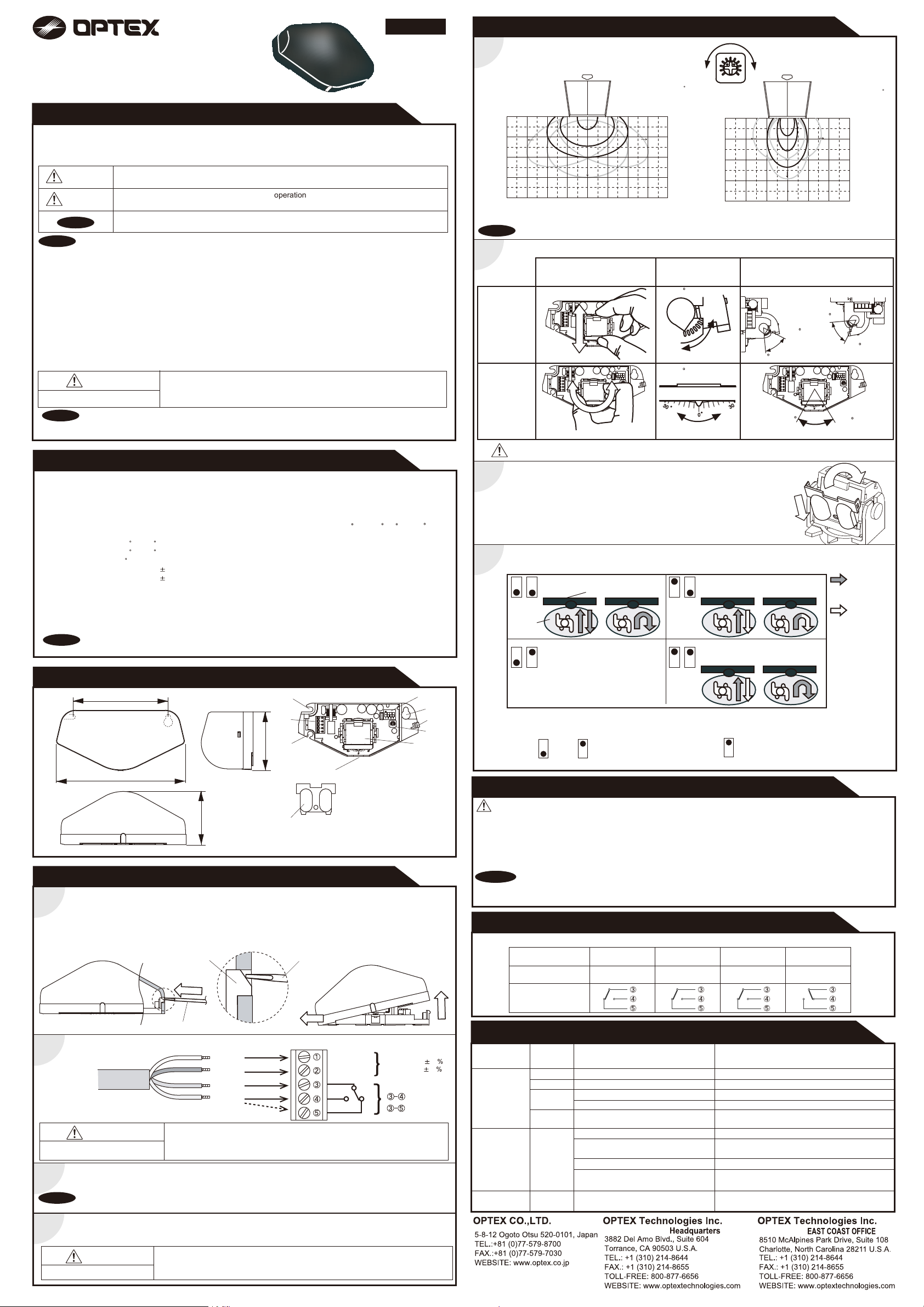
Detection area
1
Adjust the detection area with Sensitivity potentiometer.
Wide area
Mounting height:2.2m(7'3")
Vertical adjustment : +34
L H
Narrow area
Mounting height:2.2m(7'3")
Vertical adjustment : +34
MANUFACTURER'S STATEMENT
Read this operation manual carefully before use to ensure proper operation of this product.
Failure to read this operation manual may cause improper operation and may result in serious injury or death of a
person.The meanings of the symbols are as follows. Please study the following first and then read the contents of this
operation manual.
5916231 SEP 2010
WARNING
CAUTION
NOTE
Disregard of warning may cause the improper operation causing death or serious injury of a
person.
Disregard of caution may cause the improper
objects.
Special attention is required to the section of this symbol.
causing injury of person or damage to
NOTE
1. This sensor is a non-contact switch intended for header mount / ceiling mount of an automatic door.
Do not use for any other applications.
2. When setting the sensor's detection area, make sure there is no traffic around the installation site.
3. Before turning the power on, check the wiring to prevent damage or malfunction of equipments that are connected
to the sensor.
4. Only use the sensor as specified in the operation manual provided.
5. Be sure to install the sensor in accordance with the local laws and standards of the country in which the sensor is
installed.
6. Before leaving the job site make sure that the sensor is operating properly and instruct the building owner/operator
on proper operation of the door and the sensor.
7.The sensor setting can only be changed by an installer or service engineer. When changed, register the changed
setting and dates in the maintenance logbook accompanying the door.
WARNING
Danger of electric shock.
NOTE
The following conditions are not suitable for the sensor installation.
-Vibrating header or mounting surface.
-Moving objects, steel plate, emergency lights or illumination in the detection area or in vicinity.
Do not wash, disassemble, rebuild or repair the sensor, otherwise
it may cause electric shock or breakdown of equipments.
-Waterdrops or snow on the sensor.
SPECIFICATIONS
Model
Cover color
Mounting height
Detection method
Power frequency
Power density
Detection area
Vertical adjustment
Horizontal adjustment
Power supply
Power consumption
Minimum speed
Operation indicator
NOTE
The specifications herein are subject to change without prior notice due to improvements.
: REACTION ONE / REACTION TWO
: Silver / Black
: 2.0 (6'7") to 3.5m (11'5")
: Microwave doppler effect
: 24.125GHz
: <20dBm
: See Detection area
: +10 to +70 (Header mount)
+20 to +80 (Ceiling mount)
: 30 to left or right
: 12 to 24VAC( 10%)
12 to 30VDC( 10%)
: < 1.5W(<2VA at AC)
: 5cm(1 15/16")/sec.
: Green / Stand-by
Red / Detection
Green blinking / Set-up
Output
Output hold time
Response time
Operating humidity
Operating temperature
IP rate
Weight
Accessories
: Form C relay
50V 0.3A Max.(Resistance load)
: 2.0sec. / 4.0sec.
: <0.3 sec.
: <80%
: -20 C to +55 C(-4 F to 131 F)
: IP54
: 140g (4.9oz)
: 1 Cable 3m (9'10")
1 Operation manual
2 Mounting screws
1 Mounting template
1 Narrow lens*
* At the back of housing cover
OUTER DIMENSIONS AND PART NAMES
97(3 13/16")
131(5 3/16")
mm(inch)
55(2 3/16")
3
8
5
61(2 3/8")
7
6*
*Narrow lens is stored
at the back of housing
cover.
30
30
0
1. Antenna
2. Sensitivity potentiometer
3. Mounting holes
4. Dipswitches
5. Wiring hole
6. Narrow lens
7. Operation indicator
8. Terminal block
9. Cover fixing
INSTALLATION
1. Affix the Mounting template at the desired mounting position.
1
2. Drill 2 Mounting holes of ø3.4mm (ø1/8”).
3. To pass the cable through to the header, drill a Wiring hole of ø8mm (ø5/16”).
4. Remove the Mounting template.
5. Remove the Housing cover with screw driver as shown below.
Attach the sensor to the mounting surface with 2 Mounting screws.
Cover fixing
Insert
1
Screw driver
Wire the cable to the door controller properly as shown below.
2
Red
Black
White
Green
WARNING
Danger of electric shock.
1.Plug the connector of the sensor.
2.Supply power to the sensor and the sensor will automatically start the set-up mode with blinking Green.
3
3.Adjust the detection area and set the Dipswitches. (See ADJUSTMENTS)
Make sure to connect the cable correctly to the door controller before turning the power ON.
NOTE
4
The sensor does not detect objects for 10 seconds after supplying power.
Hook the Housing cover on the left side of main body to place the Housing cover.
If wiring is to be exposed, break the knockout.
Before starting the procedure, ensure that the power is turned OFF.
When passing through the cable to the hole, make sure not to tear the shield,
otherwise it may cause electric shock or breakdown of the sensor.
Screw driver
Slide
3
Power supply
12 to 24V AC 10
12 to 24VDC 10
Relay
N.O.
N.C.
L
10°
2000
3000
(6′7")
(9′10")
When the sensor is mounted at higher than 3.0m, set the SENSITIVITY to "H (high)".
Detection area angle adjustment
NOTE
2
4000
(13′1")
(3′3")
M
H
43°
01000
1000
(3′3")
Adjustment Scale
Vertical
adjustment
30
30
0
Front View
2000
(6′7")
mm(feet,inch)
10°
3000
(9′10")
1000
(3′3")
2000
(6′7")
3000
(9′10")
4000
(13′1")
4000
(13′1")
3 X 20 steps
Side View
5 X 12 steps
3000
(9′10")
10°
2000
(6′7")
+10
1000
(3′3")
Header
L
M
H
43°
1000
0
(3′3")
Angle
+80
+70
Side View
mm(feet,inch)
10°
2000
(6′7")
Ceiling
(9′10")
+20
3000
0
1000
(3′3")
2000
(6′7")
3000
(9′10")
4000
(13′1")
Horizontal
+30
30
30
0
+30
adjustment
30
30
0
30
30
0
Front View Front View Front View
CAUTION
Narrow area
3
To obtain Narrow area, place Narrow lens attached at the back of housing cover.
To place Narrow lens, follow step1&2 as shown on the right.
Dipswitches settings
4
Set Dipswitch1&2 to enable the direction recognition. (REACTION TWO Only.)
2
1
Detection
area
2
1
4
3
9
2
*Auto-caution mode(
Dipswitch3:Output hold time
1
INFORM BUILDING OWNER / OPERATOR OF THE FOLLOWING ITEMS
WARNING
1. Always keep the housing cover clean. If dirty, wipe the housing cover lightly with a cloth.
(Do not use any cleaner or solvent.)
2. Do not wash the sensor with water.
3. Do not disassemble, rebuild or repair the sensor yourself, otherwise electric shock may occur.
4. Always contact your installer or service engineer when changing the settings.
5. Do not paint the housing cover.
NOTA
NOTE
1. After applying power, wait 10 seconds then walk test detection area to ensure proper operation..
2. Do not place any objects that move or emit light in the detection area. (e.g. Plant, illumination, etc.)
CHECKING
Check the operation according to the chart below.
Sensor Status
Operation indicator
Open
2
Output Contact
TROUBLESHOOTING
Problem
Door does not
open when a
person enters
the detection
area.
Door opens
when no one
is in the
detection area.
(Ghosting)
Door remains
open
Do not touch electric part of the sensor to avoid possible breakdown of the sensor.
Bi-direction(Bi)
Door
2
1
Bi-direction
2
When Dipswitch1 is set to OFF,
Bi-direction mode is effective,
regardless of Dipswitch2 setting.
A person wavering in the detection area to be detected.)
1
Uni-direction(Uni)
Uni-direction with Auto
-caution mode*(ACM)
Dipswitch4:Immunity
4.0sec.2.0sec.
33
Power OFF
OFF
Operation
indicator
None Wrong power supply voltage. Set to the stated voltage.
Unstable
Green
Green
blinking
Green
Wrong wiring or connection failure.
Sensitivity is too low.
Wrong detection area positioning.
The sensor is being set up.
Water drops on the housing cover. Wipe the housing cover with a cloth.
Red
The detection area is overlaping with
the door.
Sensitivity is too high. Set the sensitivity lower.
Raining or snowing.
Wrong wiring or connection failure.
Possible cause
Set-up
(Approx. 10sec.)
Green blinking
If there is external interference,
set Dipswich 4 to ON.
4
Stand-by
Green
Possible countermeasures
Check the wiring and Terminal block.
Set the sensitivity higher.
Check ADJUSTMENTS.
Wait for the set-up to complete.
Adjust the detection area away from the door.
Or set Dipswitch4 to ON.
Set Dipswitch1 to ON.(REACTION TWO Only)
Or Dipswitch4 to ON.
Check the wiring and Terminal block.
2
1
: Detection
: Non-Detection
Detection
Red
WARNING
Danger of electric shock.
Do not use the sensor without the Housing cover.
When using the cable knockout, install the sensor indoors or use the rain-cover
(Separately available) otherwise electric shock or breakdown of the sensor may occur.
Page 2

FCC WARNING(For USA)
Changes or modifications not expressly approved by the party responsible for compliance could
void the user's authority to operate the equipment.
-NOTICEThis equipment has been tested and found to comply with the limits for a Class B digital device,
pursuant to part 15 of the FCC Rules. These limits are designed to provide reasonable protection
against harmful interference in a residential installation.This equipment generates, uses and can
radiate radio frequency energy and, if not installed and used in accordance with the instructions,
may cause harmful interference to radio communications. However, there is no guarantee that
interference will not occur in a particular installation. If this equipment does cause harmful
interference to radio or television reception, which can be determined by turning the equipment
off and on, the user is encouraged to try to correct the interference by one or more of the
following measures:
-Reorient or relocate the receiving antenna
-Increase the separation between the equipment and receiver.
-Connect the equipment into an outlet on a circuit different from that to which the receiver is
connected.
-Consult the dealer or an experienced radio/TV technician for help.
-NOTICE-
1.The antennas cannot be exchanged.
2.To comply with FCC RF exposure compliance requirements, aseparation distance of at least
20cm must be maintained between the antenna of this device and all persons.
IC(For CANADA)
Operation is subject to the following two conditions:
(1) this device may not cause interference, and
(2) this device must accept any interference received, indluding interference that may cause
undesired operation of the device.
 Loading...