

Page 1
PoE IP Encoder
PoE IP Encoder
PIE-1
PIE-1
No.5919560
INSTALLATION INSTRUCTIONS
( for SIP series and RLS series )
Detailed Version
FEATURES
▪ PIE-1 changes analog relay output signals (N.C.) to
original ASCII code.
▪ PIE-1 can supply power to detector using a PoE hub
or switch.
SAFETY PRECAUTION
▪ Follow all cautions and instructions in this manual
before installation.
▪ Keep this manual after installation so that you can
read when necessary.
▪ Remember the meanings of “Warning” and
“Caution” below to use the product safely.
Warning
Caution
If you ignore a warning, the user or other
people may be injured or dead.
If you ignore a caution, the user or other
people may be injured or the product or
something around it may be damaged.
CONTENTS
1
PREPARATIONS
2
SETTINGS ON THE WEB
3
REDWALL EVENT CODE SPECIFICATIONS
4
REDWALL EVENT CODE LOGGER
5
Q&A
PREPARATIONS
1
Before using PIE-1, set the IP addresses of PIE-1 and
the computer in the following procedure.
The default settings of PIE-1 are as follows.
IP Address: 192.168.0.126
Subnet Mask: 255.255.255.0
Default Gateway: 0.0.0.0
(1) Set the local area connection.
An example of IP address settings
IP Address
Subnet Mask
: 192.168.0.1
: 255.255.255.0
WarningWarning
▪ Do not repair, dismantle or modify the product
yourself.
▪ Do not touch the product with a wet hand.
▪ Be careful not to damage other interior wiring when
installing or wiring the product.
▪ Power off the product immediately if smoke, odor or
strange sound emits from the product.
▪ Do not install the product in an extremely moist place
such as a bathroom or a place where the product
may be wet.
Caution
▪ Insert the connectors securely when wiring.
CE Statement
Warning: This is a class A product. In a domestic
environment this product may cause radio interference
in which case the user may be required to take
adequate measures. (EN55022)
(2) Using Internet Explorer, access the site below.
(http://192.168.0.126/)
(3) Enter the user ID and the password below.
User ID: PIE-1
Password: OPTEX
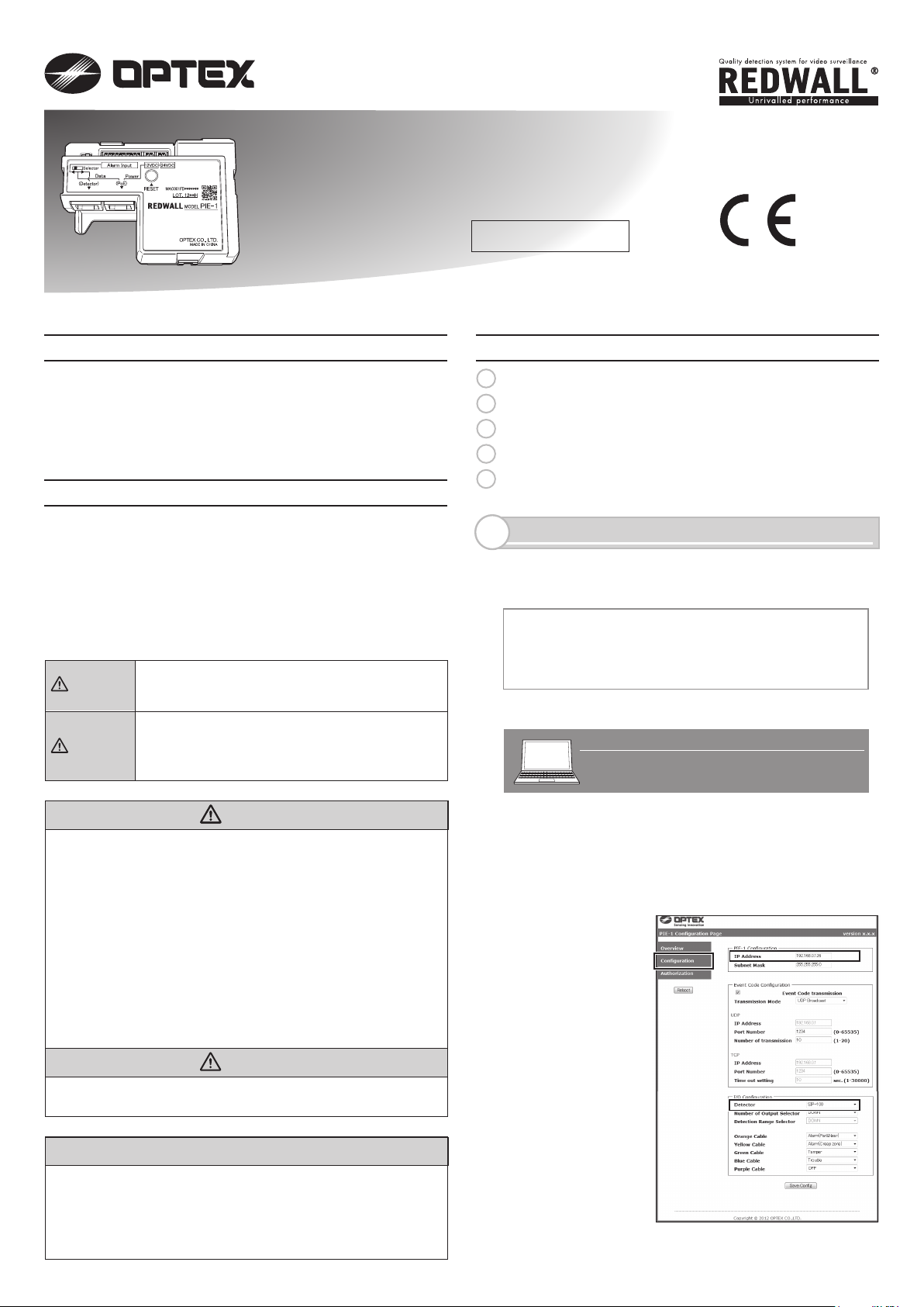
(4) Change the IP
address if
necessary.
(5) Select the
detector you
have
connected.
(6) After changing settings. Click “Save Config” button.
- 1 -
2012.5.25
Page 2

SETTINGS ON THE WEB
2
You can confirm the information below by accessing PIE-1 with Internet Explorer 8 or 9.
▪ Confirming the status of input terminals of PIE-1
▪ Confirming the transmitted data of REDWALL Event Code (R.E.C.)
▪ Confirming the software version
▪ Managing the network settings
▪ Managing the transmission settings of R.E.C.
▪ Managing the settings of alarm input
▪ Changing the user ID or password
▪ Restarting PIE-1
To access the Web screen of PIE-1, enter the URL below in the browser.
http://192.168.0.126/index.htm
When the identification screen appears, enter the user ID and the password below.
User ID: PIE-1
Password: OPTEX
The Web screen of PIE-1 consists of three sub-screens: Overview, Configuration and Authorization.
Step 1
Step 2
In the Overview screen, you can confirm the information
below:
▪ Status of input terminals of PIE-1
▪ Transmitted data of REDWALL Event Code (R.E.C.)
▪
Software version
The status of each input terminal is indicated by a color such
as Orange, Yellow, Green, Blue or Purple in the Alarm
Information, according to the alarms specified in the
Configuration screen. When a terminal has an input, the
background becomes yellow. When the alarm is OFF, the
background is gray. The R.E.C. transmission data is displayed
in the R.E.C. (REDWALL Event Code) box of the Alarm
Information.
In the Configuration screen, you can change the settings
below:
▪ Network settings of PIE-1
▪ Transmission settings of R.E.C.
▪ Settings of alarm input
After changing the settings, click the [Save Config] button at
the top and bottom of the screen to save the settings in PIE-1.
Note>>
█
PIE-1 Configuration: to change the network settings of PIE-1.
▪ IP Address: to change the IP address of PIE-1
▪ Subnet Mask: to change the subnet mask of PIE-1
▪ Default Gateway: to change the default gateway of PIE-1
- 2 -
Page 3

█
Event Code Configuration: to change the transmission settings of R.E.C.
▪ Use an arbitrary number: to define how to set the ID of Detector.
When this item is unchecked, the value of the ID of Detector is automatically set as the right-end part of the IP Address.
▪ ID of Detector: to change the number of R.E.C. You can specify the number ranging from 0 to 999.
▪ Transmission Mode: to change the transmission mode of R.E.C.
[UDP]
▪ IP Address: to change the IP address to which an R.E.C. (UDP) is transmitted.
▪ Port Number: to change the port number to which an R.E.C. (UDP) is transmitted.
▪ Number of transmission: to change the number of transmission of R.E.C. (UDP). You can specify the number within the
range from 1 to 20.
[TCP]
▪ IP Address: to change the IP address to which an R.E.C. (TCP) is transmitted.
▪ Port Number: to change the port number to which an R.E.C. (TCP) is transmitted.
▪ Time out setting: to change the duration of re-transmission of R.E.C. (TCP). You can specify the duration within the range
from 1 to 30,000 seconds.
▪ Set continuous alarm of TA/TR available: to specify the transmission method of TR/TA of R.E.C. When this item is
unchecked, TR/TA is transmitted only once. When this item is checked, TR/TA is transmitted at intervals you set in the
“Transmission interval” area.
▪ Transmission interval: to change the transmission interval of TR/TA of R.E.C.
▪ Delay time of CL transmission: to change the delay time from the point when the relay output of object detection is cleared to
the point when the CL of R.E.C. is transmitted.
█
I/O Configuration: to change the alarm settings of input terminals
▪ Detector: to select a detector connected to PIE-1
▪ Number of Output Selector: to select the switch status of the current Number of Output Selector (when SIP-100 is selected).
▪ Detection Range Selector: to select the switch status of the current Detection Range Selector (when SIP-3020, SIP-3020/5,
SIP-404, SIP-404/5, SIP-4010 or SIP-4010/5 is selected).
▪ Orange / Yellow / Green / Blue / Purple: to change the alarm color of each input terminal.
In the I/O Configuration, you can select one of nine alarm types according to the sensor connected. R.E.C. are transmitted
according to the alarm types you have selected here. When an input terminal is set to OFF in the I/O Configuration, PIE-1 does
not transmit an R.E.C. if the terminal has an input.
R.E.C. to be transmitted according to the I/O Configuration are as follows:
Alarm R.E.C.
Alarm (Far) FR
Alarm (Near) NR
Alarm (Creep) CR
Alarm R.E.C.
Alarm (Far&Near) FN
Trouble TR
Tamper TA
Step 3
In the Authorization screen, you can change the user ID and
password when accessing the web screen. After changing the
settings, click the [Save Config] button at the bottom of the
screen to save the settings in PIE-1.
- 3 -
Page 4

REDWALL EVENT CODE SPECIFICATIONS
3
<Purpose>
PIE-1 generates event codes which can be used by an NVR or VMS software to control PTZ cameras and other
devices.
<Communication methods>
REDWALL EVENT CODE can be sent to the assigned port using UDP or TCP protocol. The default port number
is “1234”.
When you connect PIE-1 to REDSCAN, REDWALL EVENT CODE is generated from REDSCAN. Please refer to
the manual for REDSCAN when you use it.
<Code format>
“PIE126 MO FR XZ CC TA”
Y1
Master
alarm
ID number of the PIE-1
Y2
Latest
alarm
Y3
Multiple
alarm
Y4
Multiple
alarm
Y10
Tamper
ID number of the PIE-1 unit consist 6 bytes as follows.
PIE + 3 bytes number (Default number is the last group of the host IP address.)
Position Command
Y1 MO/CL
Y2 FR/NR/CR/FN In case of SIP : Last alarm. Far(FR)/Near(NR)/Creep(CR)/Far and Near(FN)
- In case of Tamper/Trouble : Not available
Y3 XY/YZ/XZ In case of SIP : Multiple alarm. (Combination)
- In case of Tamper/Trouble : Not available
Description
Master alarm triggered / Master alarm cleared “CL” code is generated 10 seconds
after master alarm was cleared. This value can be changed by setting software.
CR & NR →XY, NR & FR→YZ, CR & FR or FN →XZ
Y4 CC In case of SIP : Multiple alarm. (either combination)
- In case of Tamper/Trouble : Not available
Y5-7 - Not available
Y8 TR Trouble
Y9 - Not available
Y10 TA Tamper
- 4 -
Page 5

REDWALL EVENT CODE LOGGER
4
Double-click the REDWALL Event Code Logger.exe.
Logger is a program to display REDWALL Event Codes
(R.E.C.) sent from a device on the network and to save the
information as a text in a file.
Using this program, you can check the reception of R.E.C.
This program is working on a computer which is installed
with .NET Framework 3.5 or higher. Before using this
program, obtain .NET Framework 3.5 on the Microsoft website
and install it on your computer.
█
Screen layout
▪
View all REDWALL Event Code:
To select how to display or save R.E.C. which has been received. When this item is checked, the program
displays and saves R.E.C. transmitted from all devices. When unchecked, the program displays and saves
an R.E.C. transmitted from the Target IP Address only.
▪ Target IP Address:
The IP address of a device which transmits an R.E.C. The program displays and saves an R.E.C. transmitted
from a device whose IP address you have specified here.
▪ Port Number:
The port number to which a device transmits an R.E.C.
▪
Protocol:
The protocol through which a device transmits an R.E.C.
▪ Get Start:
To begin to display and save an R.E.C. which has been received.
▪ Stop:
To stop to display and save an R.E.C. which has been received.
▪ REDWALL Event Code:
The list of all R.E.C. which have been received.
█
Operation
You can display and save an R.E.C. in the procedure below.
(1) Enter the IP address of the device which transmits an R.E.C. in the boxes of Target IP Address.
(2) Enter the port number of R.E.C. transmission to which a device transmits an R.E.C. in the box of Port Number.
(3) Select a transmission protocol of R.E.C. through which a device transmits an R.E.C.
(4) Click the [Get Start] button.
(5) When the “Save as” screen appears, define the folder where you want to save the transmitted R.E.C. and the
filename.
(6) Click the [Save] button.
█
Note
“Can’t find Target Machine” appears when no device in LAN has the IP address you have specified as the Target
IP Address or when the device whose IP address you have specified as the Target IP Address is not turned on.
Please check if you have entered the IP address correctly or if the device is turned on.
- 5 -
Page 6

Q&A
5
Problems
(1)
PIE-1 does not
turn on.
(The LED does
not turn on.)
A detector does
(2)
not turn on.
The setting
(3)
screen of PIE-1
does not appear.
The setting is not
(4)
renewed.
I have forgotten
(5)
the password.
I have forgotten
(6)
the IP address.
REDSCAN
(7)
MANAGER
cannot access
REDSCAN
The event code
(8)
is not output in
the walk test.
The output
(9)
event code is
different.
Connection
Detector
SIP,
REDSCAN
SIP,
REDSCAN
SIP,
REDSCAN
SIP, REDSCAN
SIP, REDSCAN
SIP,
REDSCAN
SIP,
REDSCAN
SIP,
REDSCAN
SIP
SIP
CheckNo.
Is the LAN connector firmly plugged to PIE-1?
Is the LAN connector plugged into the right port?
Is your Hub or Switch compliant to PoE?
Is PoE of your Hub or Switch powered on?
Is the LAN connector firmly plugged to PoE-compliant Hub or
Switch? Is the LAN connector plugged into a PoE-compliant port?
Is the LAN cable Category 5 or higher?
Is the PIE-1 powered on?
Is your Hub or Switch compliant to PoE+ (IEEE802.3at)?
(when using SIP+Heater or REDSCAN)
Did you select the correct output port, namely 24v or 12v?
Solution
Plug the LAN connector into the right
port.
Use a PoE-compliant Hub or Switch
correctly.
Plug the LAN connector into the
PoE-compliant port.
Use a Category 5 or higher LAN cable.
Refer to Q&A (1).
Use a Hub or Switch compliant to PoE+
(IEEE802.3at).
Use the correct power output.
(refer to the manual (2) and (5) provided with the product)
Is the power cable connected firmly? (Please check the
Connect the power cable firmly.
connections of PIE-1, the relay connector and the detector.)
Is PIE-1 powered on?
Are the local area settings in the computer correct?
Refer to Q&A (1).
Set the local area correctly, referring to the
manual (3) provided with the product.
SIP
Is the URL correct?
Enter the correct URL, referring to the manual
(3) provided with the product.
If you forget the IP address or password, reset
them, referring to the manual (4) (the values
are reset to 192.168.0.126).
SIP Is your browser Internet Explorer?
SIP Are more than one IP address conflicting?
Use Internet Explorer.
Connect one PIE-1 to one PC.To solve the IP
address confliction, change an IP address.
SIP Is the selector switch correct?
SIP
Did you click the “Save Config” button after setting?
Set the selector switch correctly.
Be sure to click the “Save Config” button after
change the settings.
SIP
Reset the User ID and Password to the default
values, referring to the manual (4) provided
with the product.
SIP
Reset the IP address to the default values, referring
to the manual (4) provided with the product.
REDSCAN
REDSCAN
REDSCAN Are the local area settings in the computer correct?
Is PIE-1 powered on?
Is REDSCAN working?
Refer to Q&A (1).
Refer to Q&A (2).
Set the local area correctly, referring to the
manual of REDSCAN.
REDSCAN
Are more than one IP address conflicting?
Connect one PIE-1 to one PC. To solve the IP
address confliction, change an IP address.
REDSCAN Is the selector switch correct?
Set the selector switch correctly.
Is PIE-1 powered on?SIP, REDSCAN Refer to Q&A (1).
Is the detector powered on?SIP, REDSCAN Refer to Q&A (2).
SIP Can you access the web screen of PIE-1? Refer to Q&A (3).
SIP Are the settings of connection detector correct? Select the correct connection detector.
SIP Is the alarm displayed on the web screen as you have
Connect the alarm cable firmly.
done in the walk test?
SIP Can you receive the event code with REDWALL Event
Code Logger.exe?
SIP If you can receive the event code with REDWALL Event
Set the protocol or destination of the event
code correctly on the web screen of PIE-1.
Set VMS/NVR correctly.
Code Logger.exe, the settings of VMS/NVR may be incorrect.
REDSCAN Can you access REDSCAN with REDSCAN MANAGER? Refer to Q&A (7).
REDSCAN Can you receive the event code with REDWALL Event
Code Logger.exe?
REDSCAN If you can receive the event code with REDWALL Event
Set the protocol or destination of the Event
Code correctly with REDSCAN MANAGER.
Set VMS/NVR correctly.
Code Logger.exe, the settings of VMS/NVR may be incorrect.
SIP
Did you set the connection detector correctly on the web
Select the correct connection detector.
screen of PIE-1?
SIP Does the alarm appear on the web screen of PIE-1 as you
have done in thewalk test?
Change the settings of alarm input so that the
alarm in the walk test and the alarm on the
web screen are identical.
OPTEX CO., LTD. (JAPAN) (ISO 9001 Certified) (ISO 14001 Certified)
5-8-12 Ogoto Otsu Shiga 520-0101 JAPAN TEL:+81-77-579-8670 FAX:+81-77-579-8190 URL:http://www.optex.co.jp/e/
OPTEX INCORPORATED (USA)
TEL:+1-909-993-5770
Tech:(800)966-7839
URL:http://www.optexamerica.com/
OPTEX SECURITY SAS (FRANCE)
TEL:+33-437-55-50-50
URL:http://www.optex-security.com/
OPTEX (EUROPE) LTD. (UK)
TEL:+44-1628-631000
URL:http://www.optexeurope.com/
- 6 -
OPTEX SECURITY Sp. z o. o. (POLAND)
TEL:+48-22-598-06-55
URL:http://www.optex.com.pl/
 Loading...