

Page 1
OPTEX OVS-6000 Quick Setup Guide
For detailed information, please refer to the installation manual supplied with each sensor.
The OVS-6000 utilizes an active infrared transmitter and photoelectric
receiver located in the rectangular sensor head. This Quick Setup Guide
will answer the most common installation questions, including: Mounting
location, aiming the sensor head to achieve proper detection, self-learning,
and programming.
ime)
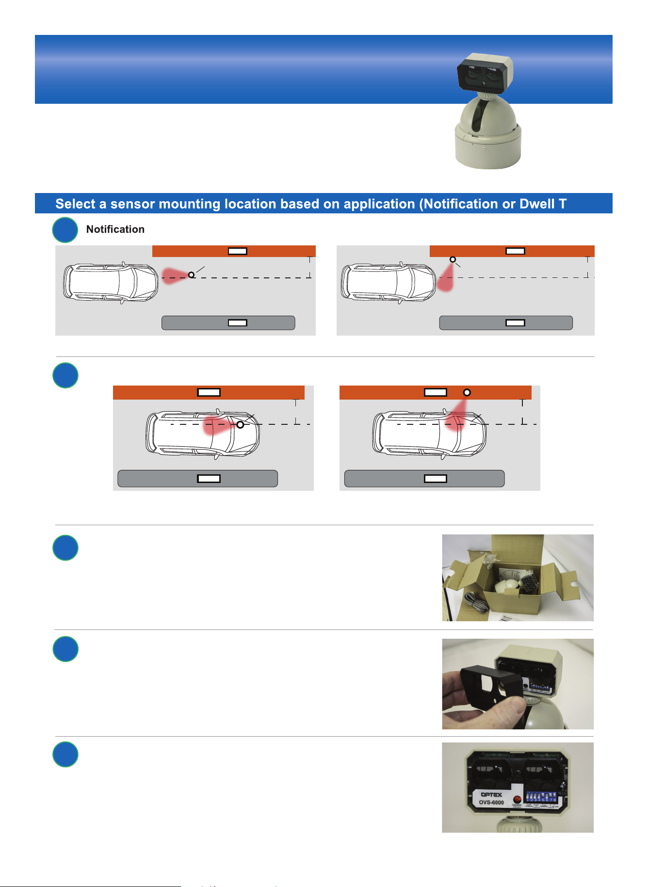
1
(detecting the approach of a vehicle) applications, vehicle clearance validation
sensor
3-4’
sensor
or
Note: Mount to the side if you don’t have vehicle clearance of the sensor (see above right); ensure vehicles will not strike the sensor.
Dwell Time (detecting the presence of a stopped vehicle) applications, vehicle clearance validation
2
sensor 3 - 4’ sensor 3 - 4’
or
Note: Mount to the side if you don’t have vehicle clearance of the sensor (see above right); ensure vehicles will not strike the sensor.
* Aim detector beams in front of tube machine
3-4’
After choosing the mounting location, open the box and remove
3
the sensor.
Note that the dipswitches are located behind the black cover, which
4
can be easily removed by pulling the cover forward.
View the Transmitter, Receiver and Dipswitches. See below for detail of
5
dipswitch settings.
(over)
Page 2
6
* Apply power - no vehicles in the detection pattern for a 10-second learning time.
Mount Sensor and Adjust the Detection Pattern
When mounted on the ceiling, the sensor head is aimed in this direction.
Loosen keeper nut and adjust sensor head so that it aims at the ground
above the driver’s side of the vehicle.
The sensor projects narrow detection beams towards the ground.
The detection area contains 4 beams, as displayed in image at
right. The IR Locator (optional) will give you the ability to locate the
individual beams. When the LEDs light up on the IR Locator, you
are within the beam area. The IR Locator Adjustment Tool can be
purchased from OPTEX. Call 800-966-7839 to learn more.
LAC-1 (optional)
7
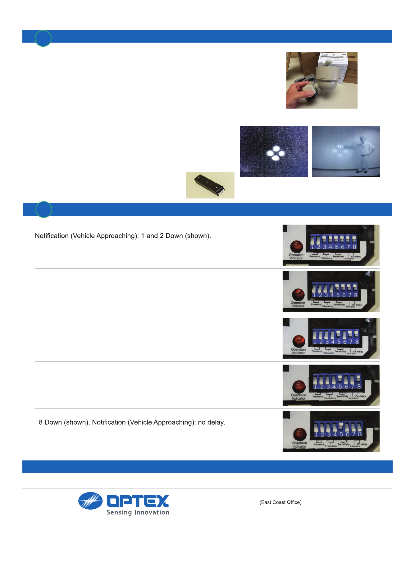
Choose Sensor Settings
1 and 2 - Presence (Vehicle) Detection Timer
Dwell Time (Vehicle Stationary): 1 Up, 2 Down
3 and 4 - Frequency
Set 3 and 4 Down (unless using 2 or more detectors with overlapping detection patterns next to each other; then, adjust to different frequencies).
5 and 6 - Adjust Detection Height Area
9 to 15 feet: 5 Up, 6 Down (shown).
12 to 24 feet: 5 Down, 6 Up.
7 - LED Indicator
7 Down (shown), LED on, turns off with detection.
7 Up, LED stays on with power.
8 - Delay
8 Up requires 2 or more beams broken within a 3-second period for Dwell
time (Vehicle Stationary).
Test and Complete Installation
18730 Wilmington Ave, Unit 100
Rancho Dominguez, CA 90220
Ph 310 667-9344
Fax 310 898-1098
Toll free 800 966-7839
www.optexamerica.com
OPTEX Technologies Inc.
8510 McAlpine Park Dr.
Suite 108
Charlotte, NC 28211
 Loading...