

Page 1
OVS-6000
ENGLISH
MANUFACTURER'S STATEMENT
Read this installation instructions carefully before use to ensure proper operation of this product.
Failure to read this operation manual may cause improper operation and may result in serious injury or death of
a person.The meanings of the symbols are as follows.
5924371 FEB 2016
WARNING
CAUTION
NOTE
NOTE
1. This product is a non-contact switch intended for header mount or wall mount for vehicle detection.
Do not use for any other applications.
2. When setting the sensor's detection area, make sure that there is no traffic around the installation site.
3. Before turning the power ON, check the wiring to prevent damage or malfunction of equipment connected to
the product.
4. Only use the product as specified in the operation manual provided.
5. Be sure to install and adjust the sensor in accordance with the local laws and standards of the country in which
the product is installed.
6. Before leaving the installation site make sure that the product is operating properly and instruct the building
owner/operator on proper operation of the product.
7.The product settings can only be changed by an installer or service engineer. When changed, the
changed settings and the date shall be registered in the maintenance logbook.
Danger of electric shock
Disregard of the warning symbol can cause improper operation which may cause death
or serious injury.
Disregard of the caution symbol can cause improper operation which may cause injury of a
person or damage the object.
Special attention is required to the section of this symbol.
It is required to check the operation manual if this symbol is shown on the product.
WARNING
Do not wash, disassemble, rebuild or repair the sensor, otherwise
it may cause electric shock or breakdown of the equipment.
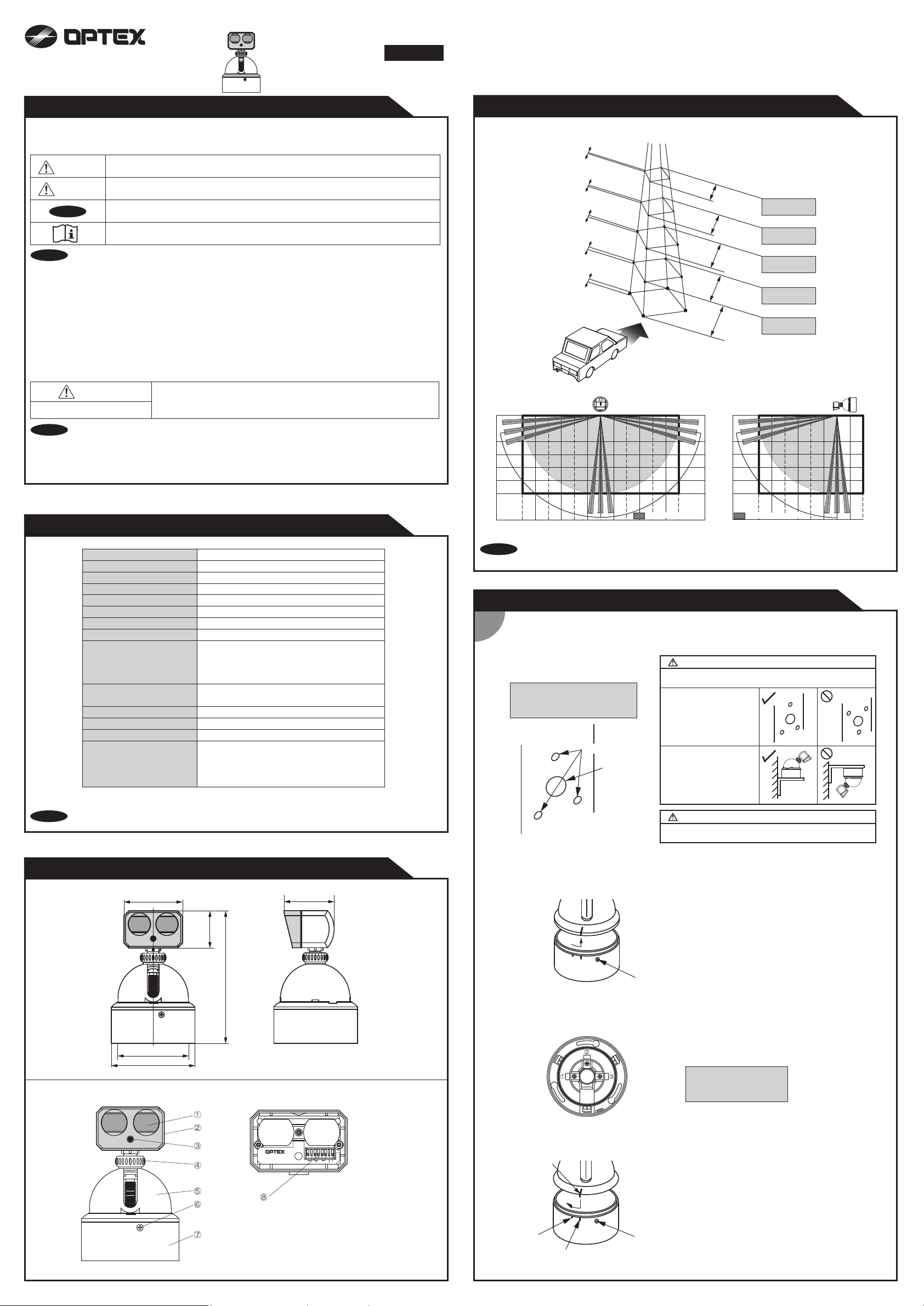
DETECTION AREA
3 15/16"
(100)
5 7/8"
(150)
7 7/8"
(200)
9 13/16"
(250)
11 13/16"
(300)
FRONT VIEW SIDE VIEW
1'4 9/16"
(420)
2' 13/16"
(630)
2' 9 1/16"
(840)
3' 5 5/16"
(1050)
4' 1 5/8"
(1260)
6' 6 3/4"(2m)
9' 10 1/8"(3m)
13' 1 1/2"(4m)
16' 4 7/8"(5m)
19' 8 1/2"(6m)
[feet, inch(mm)]
NOTE
The following conditions are not suitable for sensor installation.
-Fog or exhaust emission around the detection area
-Wet floor
-Vibrating header or mounting surface
-Moving objects, steel plate, emergency lights or illumination in the detection area or in vicinity
-Highly reflecting floor or highly reflecting objects around the detection area
SPECIFICATIONS
Detection range
Detection method
Detection range (Vertical)
Detection range (Right & Left)
Detection range (right & left)
Power supply
Power consumption < 2.5W (24VDC)
Current consumption
Operation indicator
Output
Relay hold time
Operating temperature
Weight
Accessories 1 Operation manual
OVS-6000Model
6' 6 3/4" to 19' 8 1/2" (2.0 to 6.0m)
Active infrared reflection method
-80° to +80° (Deep/Shallow)
360°
24VDC
< 105mA (24VDC)
Stand-by
Detection(Only one area)
Detection(Any areas)
Infinite detection
: LED ON
: LED OFF
: LED Slow Blinking
: LED Fast Blinking
"Form A" relay 100VAC 1A
30VDC 0.1A Max.
Approx. 1.0sec.
-4 to 131°F (-20 to +55°C)
290g (10.2oz)
2 Mounting screws
1 Mounting template
1 Cable 9'10"(3m)
9' 10 1/8"
NOTE
16' 4 7/8"
(5m)
The actual detection area may become smaller depending on the ambient light, the color / material of
the object or the floor as well as the entry speed of the object.
(3m)
3' 9/32"
(1m)
INSTALLATION
Install Sensor
1
(1-1) Drill three mounting holes.
Affix the mounting template put “up side”
sign up and make holes. Drill a wiring hole
when you pass the cable into the wall.
・Mounting screw holes : ø1/8"(3.3mm)
(Three positions)
・Wiring hole : ø19/32"(15mm)
(One in center)
Mounting screw holes
3' 9/32"
0
(1m)
Wiring holes
: Actual detection area
9' 10 1/8"
16' 4 7/8"
(3m)
6' 6 3/4"
(2m)
9' 10 1/8"
(3m)
13' 1 1/2"
(4m)
16' 4 7/8"
(5m)
19' 8 1/2"
(6m)
:
Actual detection area
16' 4 7/8"
(5m)
(5m)
CAUTION : Risk of product failure.
Do not install sensors upside down.
Otherwise rain water makestroubles.
Right position of the
mounting screw holes when
install on the side pole.
Right sensor position
whenuse a angle.
9' 10 1/8"
(3m)
3' 9/32"
(1m)
3' 9/32"
0
(1m)
6' 6 3/4"
(2m)
9' 10 1/8"
(3m)
13' 1 1/2"
(4m)
16' 4 7/8"
(5m)
19' 8 1/2"
(6m)
NOTE
The specifications herein are subject to change without prior notice due to improvements.
OUTER DIMENSIONS AND PART NAMES
OVS-6000
2 3/4"(70)
Mounting pitch ø85 (x3)
ø100
"
44.5)
1 3/4
(
6 1/4"(158.5)
Without sensor head cover
2 3/4"(70)
[inch(mm)]
WARNING : Danger of electric shock.
Make sure to remove burr in mounting holes otherwise
damaged cable may cause electric shock.
(1-2) Put attached screws into mounting holes temporary.
(1-3) Break off basement from sensor unit.
Sensor
Basement
Lock screw
(1-4) Set basement onto temporary screws of (1-2)
(1-5) Wiring onto basement (refer to 3-1)
Wiring should be allowed sign of basement.
① Power supply ••• Red
② GND ••• Black
③ Signal ••• White
(1-6) Set sensor unit on basement.
1, Loose the lock screw of basement full well.
2, Basement can break off when rotate anticlockwise.
OVS-6000
Operation
indicator
Presence Sensitivity
Frequency Indicator
On delay
① Detection window
② Sensor head
③ LED indicator
Sensor adjust
joint mark
Sensor
Basement
1, Push sensor unit onto basement adjust joint mark.
2, Rotate sensor clockwise to prescribed position.
3, Tight up the lock screw.
④ Sensor head lock nut
⑤ Main unit
⑥ Base lock screw
⑦ Basement
⑧ Mode setting switch
Fixed position
Lock screw
Mounting basement
adjust joint mark
Page 2
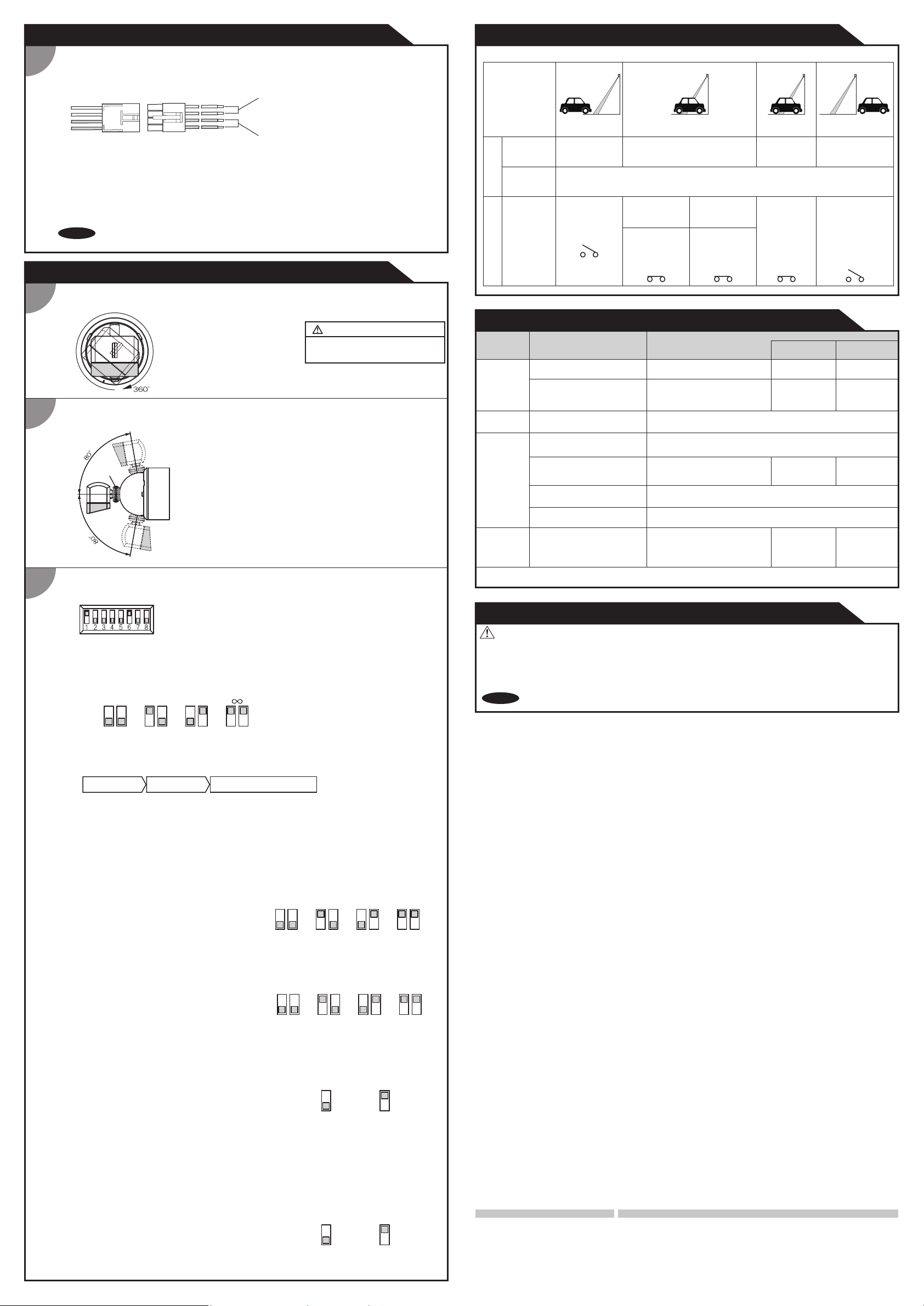
INSTALLATION
HOW TO WIRING
2
CHECKING
Check the operation in the operation mode according to the chart below.
< Wiring to the controller > Signal output (Yellow)
Relay output (N.O. / Non voltage contact.)
100VAC 1A, 30VDC under 0.1A
Power supply (Gray) 24VDC
Penetrate conector to the end.
If connector plugged not enough, signal will not stable.
< Sensor connecting cable setting >
Take care following matter when connect sensor cable.
NOTE Sensor cable sensor to sensor : Please use VCTF cable 0.75mm
Cable length : Please use cable within 32' 9 11/16"(10m) long between sensor to sensor.
ADJUSTMENTS
Adjust detection area of right & left direction.
1
Rotate sensor head angle which
position you want.
It can be revolved 360˚.
Horizontal angle of detection area
adjustment is as left picture.
Adjust detection area of vertical direction.
2
1, Loose sensor head lock nut to anticlockwise direction.
2, Move sensor head angle which you want. And tighten lock nut.
Lock nut
Adjust mode switches.
3
Adjust mode switch is found pull out sensor head cover. Please set dip switches.
(3-1) Adjust presence detection time setting
Adjust presence time by mode switch [1] & [2]
Attention : All detection area are adjusted.
2 sec. 60 sec.15 sec.
1 2 1 21 2
< Presence detection >
After power ON, please wait 10 sec without moving object in the detection area.
Presence detect function will be done by this.
Power ON Wait 10 sec Presence detection mode
It can be moved up to 80 degrees and down to 80 degrees.
[1] & [2], Presence detection timer. (Sec.)
[3] & [4], Frequency switch setting.
[5] & [6], Adjust detection area length. (Sensitivity)
[7], Adjust LED indicator setting.
[8], Adjust On delay.
Other than Infinity, will be changed to the presence
time is 10 minutes when the area has multiple
1 2
detection.
2
.
CAUTION : Risk of product failure.
Never rotate sensor head over three
rounds otherwise cable will be broken.
Entrance
(Image)
Stopped in the
area
OFF or
Blinking
Within
presence
time
Passed the area
ON
1.0sec. after
passing
OFF
OFF at
detection
setting
Always turn
setting
OVS-6000
Output Indicator
ON
Outside of the
area
ON
OFF
Entry into the area
OFF or Blinking
On delay
detection:
Normal setting
Entry into
the area
ON
ON
On delay
detection:
3sec. setting
Stopped 3 sec. or
more in the area
ON ON
TROUBLESHOOTING
Problem Possible countermeasures
Does not work
Does not work
sometime.
It works on
normal
operation.
Sensor signal
keep on.
If the trouble cound not solve, please call installar or service staff.
Possible cause
Power voltage
Wire disconnection, connect
trouble.
Dirty on the window.
Moving object or light source in
the detection area.
Detective area of other sensor
is lapped over.
There is some noisy machine
near sensor.
Water droppes on the window.
Change the floor condition
during presence mode.
Title No.
Set to the stated voltage.
Check the wireing and connector.
Clean up the dirty on the window.
Adjuct detection area or put out the moving object.
Change frequency switch by each
sensors.
Please take the noisy machne away from sensor.
Please re-install in order to avoide the rain water.
Please turn OFF the power and
ON again.
SPECIFICATIONS
INSTALLATION
ADJUSTMENTS
ADJUSTMENTS
(1-5)
Wiring onto
basement
(3-2)
Adjust frequency
switch setting
(3-1)
Adjust presence
detection time
setting
INFORM BUILDING OWNER / OPERATOR OF THE FOLLOWING ITEMS
WARNING
1. Always keep the detection window clean. If dirty, wipe the window with a damp cloth. Do not use any cleaner / solvent.
2. Do not wash the sensor with water.
3. Do not disassemble, rebuild or repair the sensor yourself, otherwise an electric shock may occur.
4. Always contact your installer or service engineer when changing the settings.
5. Do not paint the detection window.
NOTE
1. When turning the power ON, always walk-test the detection area to ensure the proper operation.
2. Do not place any objects that move or emit light in the detection area. (e.g. plant, illumination, etc.)
< Infinity mode switch setting >
When Infinity presence deteation mode is on, LED indicator is [Fast Blinking], and keep detection during
the object is in the detection area.
< CAUTION : When you use infinity mode on >
If the reflection ratio of floor condition will be changed by sudden rain or heavy snow, sensor will be filure
and keep detection.
If happen above situation, please cut power OFF and ON again. (Reset sensor)
(3-2) Adjust frequency switch setting
Mode switch [3] & [4] could adjust four kinds of
frequency position.
< Frequency switch setting >
When using more than one sensor close to each other, set the frequency different for each sensor.
(3-3) Adjust sensor detection area length (Sensitivity)
Mode switch [5] & [6] could adjust detection area
length (Sencitivity).
Set the sensitivity according to the mounting height.
Values below dipswitch are reference only.
< Detection area length switch setting >
[Detection area length] is lough indication. Depend on object or enviroment the effectual sensitivity will be
changed. Please re-adjust the swcitch position.
(3-4) Adjust LED indicator setting
Mode switch [7] turn on the LED indicator in usual.
1 2 3 4
3 4 3 4 3 4 3 4
L: 2~4m M: 3~5m H: 4~6m
5 6 5 6 5 6 5 6
When sensor
detect object LED
light turn off.
7 7
When sensor
detect object LED
light turn on.
Reserved
< Adjust indicator switch setting >
・
Turn on when detect : When sensor detect object LED light turn off. LED light indicator is on when waiting.
・Always turn on: LED light indicator is always turn on wheneven sensor detect object or not.
When you getting close to the detection point centor on the floor, you can find the LED indicator light is
more bright. To use this function, [Always turn on] mode can help to check the detection area on the floor.
After check and adjust the detection area, please set the switch to [Turn on when detect] mode.
(3-5) On delay setting
Mode switch [8] could On delay setting.
< On delay setting >
・Normal detection mode: When sensor detect object relay will be on.
・
On delay mode:
When detect objec the sensor relay will be turned on, after keep stay in the area 3 sec.
OFF 3sec.
8
8
Manufacturer
OPTEX Co.,LTD.
5-8-12 Ogoto Otsu 520-0101, Japan
TEL.: +81(0)77-579-8700
FAX.: +81(0)77-579-7030
WEBSITE:
www.optex.co.jp/as/eng/index.html
North and South America Subsidiary
OPTEX INCORPORATED
18730 S. Wilmington Avenue, Suite 100
Rancho Dominguez CA 90220 U.S.A
TEL.: +1-800-877-6656
FAX.: +1(310)898-1098
WEBSITE: www.optextechnologies.com
East coast office
8510 McAlpines Park Drive, Suite 108
Charlotte, NC 28211 U.S.A.
TEL.: +1-800-877-6656
FAX.: +1(704)365-0818
WEBSITE: www.optextechnologies.com
 Loading...