

Page 1

(01.03) 2.2.4 / pag. 1
Before using, read this instruction manual thoroughly for proper installation procedures.
[!] CAUTION
BE CAREFUL NOT TO BE STRUCK BY THE DOOR
This product is a door activating non-contact sensor which is to be mounted to/into the transom of an automatic door or to
the ceiling. Do not use it for other applications.
D etection Area
The detection area refers to the space where the sensor b ody is receiving infrared rays.
D etection Method of O P-08C
This product outputs a signal when there is a difference in temperature between the floor surface of the detection area and
an entering person.
Actual D etection: D etection may be difficult in the following cases:
-When the floor temperature has increased to a point where there is little difference between the person and floor
surface.
-When someone approaches the door from a direction other than the front.
[!] ATTENTION
* Do not install the OP-08C beyond a distance of 4 m.
The sensor may not be able to detect a human body at distances greater than 4 meters.
* Be sure to use a beam switch in combination with the OP-08C to provide a back-up safety device.
Even if there is a person standing near the door, it may start closing.
* Affix the accessory area masking seal properly. If it is not affixed properly, sensitivity will be reduced dramatically
and an entering person may be struck by the door.
PASSIVE INFRARED SENSOR
PEOPLE FRIENDLY
©
READ FIRST
INSTRUCTION MANUAL
• O P-08CW (White)
• O P-08CBL (Blac k)
[!] ATTENTION
WATCH OUT FOR THE DOOR
Do not use the OP-08C to detect the objects (push cart, etc.) other than human bodies.
The OP-08C must recognize a temperature change to activate. A push cart may or may not have the required temperature
change to activate the sensor.
N ote: This p roduct d etects only changes in temperature and will not d etect a m otionless object!
SPECIFICATIONS
M odelOP-08C
Mounting Height Within 4.0 m.
Detection Method Passive infrared detection
Current Draw 50 mA Max.(at 24 V DC)
Power Supply 12-24 V AC/DC
Detection area See drawing on page 3.
Output ContactForm C Relay, 24 V DC, w ithin 1 A (Resistance Load)
Power/Operating
Indicator
LED ON: Standby
LED OFF: Detection
Relay Hold Time Approx. 1.5s
Operating Temperature -20°C ~ +55°C (-4°F ~ +131°F)
Weight 90g (3.2oz)
Accessories
2 m Connection Cable, 2 Mounting Screws, Mounting Template, Area Masking S eal
Specification subject to change without prior notice.
Page 2

(01.03) 2.2.4 / pag. 3
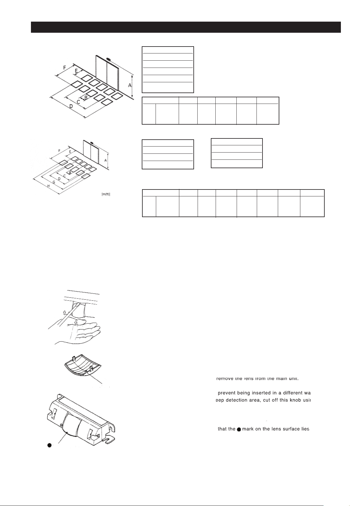
BC DEF
2.5(8.2) 0.3(1.0) 1.8(5.9) 3.6(11.8) 0.8(2.6) 2.3(7.5)
A 3.0(9.8) 0.4(1.3) 2.1(6.9) 4.3(14.1) 1.0(3.3) 2.8(9.2)
4.0(13.1) 0.5(1.6) 2.9(9.5)5.7(18.7) 1.3(4.3) 3.7(12.1)
ADJUSTMENT (Turn on the power )
Confirmation of the detection area
This product is made up of the detection area shown in the diagrams
above.
A Mounting Height
B Area Width
C Area Width
D Area Width
E Area Depth
F Area Depth
A Mounting Height
B Area Width
C Area Width
D Area Width
BC DEFG H
2.5(8.2) 0.5(1.6) 1.5(4.9) 2.5(8.2) 1.4(4.6) 3.3(10.8) 3.0(9.8) 5.0(16.4)
A 3.0(9.8)0.6(2.0) 1.8(5.9) 2.9(8.5) 1.6(5.2) 3.9(12.8) 3.7(12.1) 6 .0(19.7)
4.0(13.1) 0.8(2.6) 2.5(8.2) 3.9(12.8) 2.2(7.2) 5 .2(17.1) 4.9(16.1) 8 .1(26.6)
W ide and Deep D etection A rea
Standard D etection A rea
< Caut ion >
This p roduct uses a m ethod of detecting the change in
temperature w hen a person enters the detection area.
A ccording to the background temperature, the detection
s ensitivity may b ecome higher or l ower.
Further, b ecause only changes in temperature are detected,
a person w ho is not moving will not be detected.
Selection of the w ide & Deep detection area and s tandard
detection area.
In this product, it is possible to change between the wide & deep d etection area
and standard detection area by inserting the lens. When shipped from the factory,
the product is set to the standard detection area.
< To set to the wide & deep detection area>
(1)Remove the panel cover.
(2)
(3)
(4)
the mounting surface side
.
Area Depth
Area Depth
Area Width
Area Width
E
F
G
H
k
n
mar
k
(01.03) 2.2.4 / pag. 2
CONSTRUCTION
(1)
Main body
(2)
Relais inversion switch
(3)
(4)
(5)
(6)
(7)
INSTALLATION
Installing the main body
(1)Affix the mounting template to your desired position on the transom or ceiling
(mounting height within 4.0m).
(2)Drill mounting holes (Ø 3.4 mm) as indicated on the mounting template. If
concealed wiring is preferred, drill a wiring hole (Ø 8 mm.) After drilling holes,
remove the mounting template.
(5)Connect the connector for the main body to that of that wiring cord. To disconnect
them, press both knobs and pull them apart.
< Connecting the Connectors >
Insert the connectors deeply into each other. Otherwise, the OP-08C may
malfunction due to a contact failure.
(4)As shown in the left figure, remove the housing cover. Using the accessory
mounting template, affix the main body. Attach the main body to the transom,
leaving about 10 mm. of the screws's threads exposed.
• Grey: Power source
• Grey: Power source
• White: COM
• Yellow:
• Green:
12 to 24 V. AC/DC
4 m
(13,1 ft)
max.
< Precautions for M ounting >
- Do not place swaying objects, such as a potted plant, flag or banner in the
detection area. The sensor may not function properly.
-When using wiring knockout, be sure to install the OP-08C in a location
protected from rain. If exposed to rain, water may enter the housing and
damage the device.
(3)Connect a wiring cord to the door controller.
N ote that the wiring method differs depending on setting of the
r elay inversion switch.
< When the relay inversion switch is "Fail-Safe" >
Install the main body in such a manner that the connector can be connected easily.
• Grey: Power source
• Grey: Power source
• White: COM
• Yellow:
• Green:
< When the relay inversion switch is "Fail-Secure">
12 to 24 V. AC/DC
N.O.
N.C.
N.O.
N.C.
Sensitivity selector switch
Transom mounting hole
Overhead mounting hole
Lens
Power/Operation indicator lamp (Green indicator lamp)
re
y
Whit
e
ree
n
Yell
ow
To Door Controller
N.O.
N.C.
Page 3
(01.03) 2.2.4 / pag. 3
BC DEF
2.5(8.2) 0.3(1.0) 1.8(5.9) 3.6(11.8) 0.8(2.6) 2.3(7.5)
A 3.0(9.8) 0.4(1.3) 2.1(6.9) 4.3(14.1) 1.0(3.3) 2.8(9.2)
4.0(13.1) 0.5(1.6) 2.9(9.5)5.7(18.7) 1.3(4.3) 3.7(12.1)
ADJUSTMENT (Turn on the power )
Confirmation of the detection area
This product is made up of the detection area shown in the diagrams
above.
A Mounting Height
B Area Width
C Area Width
D Area Width
E Area Depth
F Area Depth
A Mounting Height
B Area Width
C Area Width
D Area Width
BC DEFG H
2.5(8.2) 0.5(1.6) 1.5(4.9) 2.5(8.2) 1.4(4.6) 3.3(10.8) 3.0(9.8) 5.0(16.4)
A 3.0(9.8)0.6(2.0) 1.8(5.9) 2.9(8.5) 1.6(5.2) 3.9(12.8) 3.7(12.1) 6 .0(19.7)
4.0(13.1) 0.8(2.6) 2.5(8.2) 3.9(12.8) 2.2(7.2) 5 .2(17.1) 4.9(16.1) 8 .1(26.6)
W ide and Deep D etection A rea
Standard D etection A rea
< Caut ion >
This p roduct uses a m ethod of detecting the change in
temperature w hen a person enters the detection area.
A ccording to the background temperature, the detection
s ensitivity may b ecome higher or l ower.
Further, b ecause only changes in temperature are detected,
a person w ho is not moving will not be detected.
Selection of the w ide & Deep detection area and s tandard
detection area.
In this product, it is possible to change between the wide & deep d etection area
and standard detection area by inserting the lens. When shipped from the factory,
the product is set to the standard detection area.
< To set to the wide & deep detection area>
(1)Remove the panel cover.
(2)
(3)
(4)
the mounting surface side
.
Area Depth
Area Depth
Area Width
Area Width
E
F
G
H
k
n
mar
k
Page 4
(01.03) 2.2.4 / pag. 4
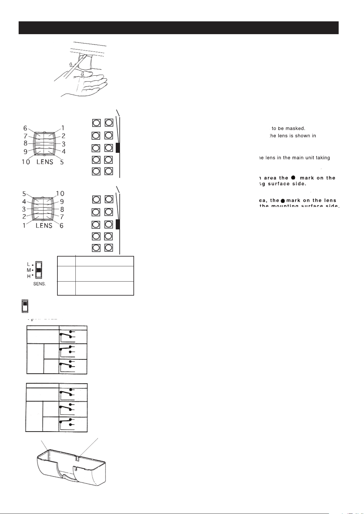
Adjusting of the detection area (Masking)
Detection areas can be masked by affixing the area masking seal to the lens area.
(1)Remove the panel cover.
(2)Using a slotted screwdriver, remove the lens from the main unit.
(3)Peel off the area masking seal from the inside of the panel cover, and affix
on the parts of the lens corresponding to the area
s
The relationship between the detection areas and
t
the diagram at left.
(4) After affixing the area masking seal, replace t
h
care not to mistake the lens direction.
ADJUSTMENT (Turn on the power)
Setting the sensitivity selectors switch
Set the sensitivity selector switch, referring to the mentioned at left values.
‘Normlly’ set it to "M".
Setting the relay inversion switch
Set the state of the relay contact for power-off (power failure, etc.)
FAIL-SAFE
At power-off, the relay contact is closed and the door is opened.
FAIL-SECURE
At power-off, the relay contact is open and the door is closed.
Mounting the housing cover
Mount the housing cover to the main body.
In the situation where the wiring is to be left exposed, use cutting nippers to
break out the knockout for the exposed w iring shown in the figure at left.
When the unit is to be attached to the ceiling, cut out the ceiling knockout of
the panel cover.
(1) Cut into the cover using the cutting nippers.
(2)Break out the top panel by hand.
- W hen using the wide & deep detectio
n
l ens surface should be on the m ounti
n
- When using the standard detection ar
e
< Caution>
Note that the positions for attaching the area masking seal are different for the
standard detection area and wide & deep detection area.
L2m (6.6ft) U nder
M2 (6.6)~3m (9.8ft)
H3 (9.8)~4m (13.1ft)
FAIL-SAFE
FAIL-SECUR
E
Exposed Wiring
Knockout
Overhead Mounting
Knockout
DOOR
OP-08C
Standard Detection
Area
Wide & Deep
Detection Area
SAFE
tate of Sensor
State of Rela
y
At power-of
f
A
t
ower-o
n
r
een
Yell
ow
Whit
e
ree
n
ree
n
Yell
ow
Yell
ow
Whit
e
Whit
e
A
t
standb
y
A
t
standb
y
tate of Senso
r
tate of Rela
y
At power-of
f
A
t
ower-o
n
A
t
standb
y
A
t
standb
y
ree
n
ree
n
ree
n
Yell
ow
Yell
ow
Yell
ow
Whit
e
Whit
e
Whit
e
6
1
7
2
3
4
8
9
10
5
DOOR
OP-08C
5
10
4
9
8
7
3
2
1
6
Page 5
(01.03) 2.2.4 / pag. 5
ADJUSTMENT (Turn on the power)
Operation check
Check the operations in the following order.
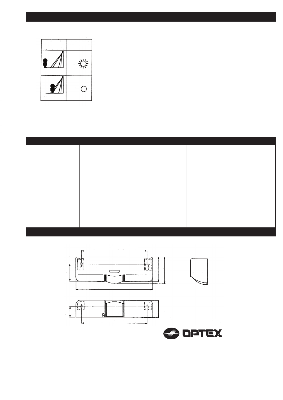
( 1 ) Make sure that the power is turned on. (The power/operation indicator lamp is
illuminated).
( 2 ) After turning on the power, this product will not be activated for about 20 seconds
due to the required warm up time. (The power/operation indicator lamp is illuminated).
( 3 ) After the warm up time, enter the detection area to make sure that the sensor
functions properly. (When it functions, the power/operation indicator lamp is turned
off.)
Maintenance
- When the OP-08C becomes dirty, dip a cloth in neutral detergent and wipe it lightly.
Do not use any organic solvents such as thinner, benzine, because they may damage
the surface of the product.
Do not directly wash the sensor with water. Water may enter inside and damage the
device.
- Never disassemble or repair the equipment. There are no user servable parts.
- Handle carefully so that you do not damage the lens. If the lens is damaged, the sensor
may not function properly.
Problem Possible cause Solution
Does not function 1 . Disconnected or defective connection. 1 . Check the wiring and connector, and
correct the defect, if any.
Does not operate from 1 . Insufficient sensitivity. 1 . Set the sensitivity switch to a higher level
time to time
2 . Passing of a push cart, etc. 2 . The OP-08C may have difficulty detecting
objects other than human bodies.
Operates by itself 1. There is a moving object such as flag, banner, potted 1 . Move the object outside the detection area.
plant in the detection area.
2 . Passing of a dog or cat. 2 . The OP-08C detects its passage because
there is a change in temperature with
respect to the floor surface.
TROUBLESHOOTING
OUTER DIMENSIONS
5907170 96.7 MADE IN JAPAN.
Entry Motion
(Image)
Green Indicator
Lamp
Outside the
Detection Area
Inside the
Detection Area
ON
OFF
Mounting Pitch 123 (4.84)
Mounting Pitch 123 (4.84)
145 (5.71)
32.8 (1.29)
45.6 (1.80)
49.5 (1.95)
19.5 (0.77)
31.5 (1 .24
)
[ mm (inch) ]
. .
:
Tiber 2
2491 DH The Hague
P.O. Box 24009
2490 AA The Hague
The Netherlands
TEL.: +31 (0)70 419 41 00
FAX : +31 (0)70 317 73 21
E-MAIL: [email protected]
WEBSITE: www.optex.nl
 Loading...