

Page 1
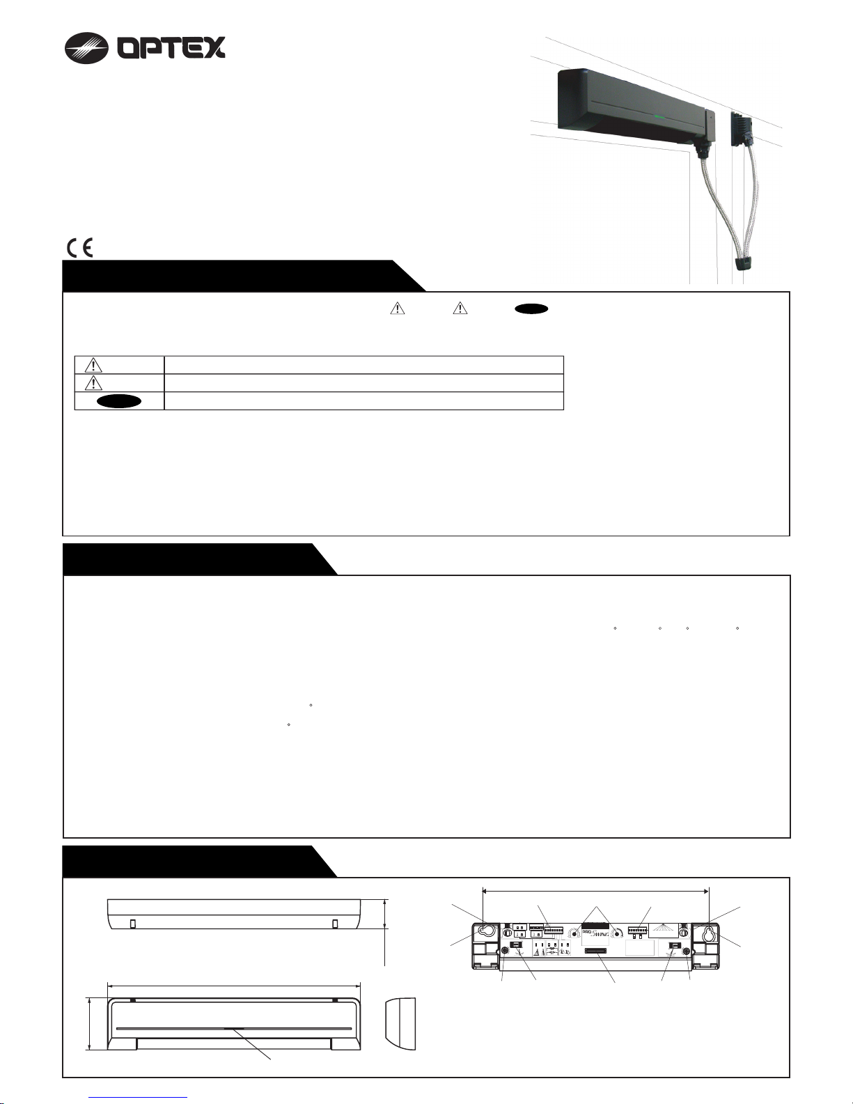
(1) Connector
(2) Sensitivity Potentiometer
(3) Mode Setting Switches
( Area Depth Adjustment, Auto Learning Timer,
Frequency, Rain Mode, Snow Mode )
(4) Area Width Switch
(5) Threshold Area Angle Screw
(6) Threshold Area Angle Gauge
(7) Swing Area Angle Gauge
(8) Swing Area Angle Screw
(9) Mounting Holes
(10) Operation Indicator
OPERATION INDICATOR
THRESHOLD AREA
SENSITIVITY
POTENTIOMETER
MaxMin
SWING AREA
SENSITIVITY
POTENTIOMETER
0deg
+5deg
‑5deg
DEEP
SHALLOW
SWING AREA DEPTH ADJUSTMENT
0deg
+5deg
‑5deg
DEEP
SHALLOW
FREQUENCY SWITCH
132
3
Each number of Area
can be eliminated
by using each dip‑SW.
AREA WIDTH SWITCH
OA-603
DEEP
SHALLOW
DEEP
SHALLOW
DEEP
PATTERN
SHALLOW
PATTERN
THRESHOLD AREA DEPTH ADJUSTMENT
AUTO LEARNING TIMER
12
15SEC.
12
12
12
6
DEEP
6
SHALLOW
AREA DEPTH
MaxMin
5
NORMAL
5
SNOW
SNOW MODE
30SEC.60SEC.120SEC.
:Stand‑by
:Doorside Det.
Green
Red Blink
Red
Yellow Blink
:Teaching
:Presence Det.
OPERATION INDICATOR
4
NORMAL
4
RAIN
RAIN MODE
Active Inactive
1 2 3456 7 8
CONNECTOR
CONNECTOR
DEEP
PATTERN
SHALLOW
PATTERN
HINGE SIDE
7
RIGHT SIDE
7
LEFT SIDE
SENSOR SIDE
SWING SIDEAPPROACH SIDE
8 8
These DipSW(7,8) are only for door mount.
5728770
56.5(2 1/4")
275(10 3/4")
32(1 1/4")
Model : OA-603
Cover color type : Black , Slilver
Mounting Height : 2.0m (6’7”) to 2.5m (8’2”)
Detection Area : See the chart in “ADJUSTMENT”.
Detection Method : Active Infrared Reflection
(Presence Detection Type)
Detection Angle : Threshold Area ±5
(Inside & outside)
Adjustments :Swing Area ±5
(Inside & Outside)
Operation Indicator :Green : Stand-by
Blinking Red : Threshold Area Detection Active
Red : Swing Area Detection Active
Blinking Yellow :Learning
OUTER DIMENSIONS
SPECIFICATIONS
[mm (inch)]
248 (9 3/4”)
Operation Indicator
Insure proper setting of Mode switch #8 indicating Approach side or Swing side sensor.
ELITE
Swing Door
Door Mounting Sensor
(1)
(1)
(3)
(4)
(2)
(6) (7) (8)
(9)
(9)
(10)
MANUFACTURER'S STATEMENT
For ease of installation and proper operation read thru this manual (especially
WARNING
CAUTION
NOTE
) prior to installing and adjusting the sensor system.
Failure to read and follow the instructions in this manual may cause improper sensor operation resulting in serious injury or death.
This product is a non-contact activating switch intended for door mounted of an automatic door.
Do not use it for any other applications; otherwise proper operation and safety cannot be guaranteed.
1.Set door speeds and verify proper operation of door manufacturer’s equipment prior to applying power to the sensor system.
2.Do not install the sensor where it might be directly sprayed with rainwater.
3.Verify proper wiring prior to applying power to the sensor system to prevent damage to equipment.
4.When setting the sensor’s area pattern, make sure there is no traffic around the installation site.
5.Do not attempt to rebuild or repair sensor heads or control unit. Contact an address in this manual for replacement products.
6.Only use the sensor as specified in the supplied instructions.
7.Walk test the installation to verify operation is in compliance with all local laws, codes and standards of your country.
8.Upon completion of installation and adjustments, instruct the owner/operator on proper operation of the door and sensor system.
Identify any switches/breakers that will place the door out of service when unsafe or improper operation is identified.
Current Draw : 120mA Max
Response Time : < 0.3 second
Operating Temperature : -20
C to +55 C (-4 F to +131 F)
Weight : 230g (8.2oz.)
Accessories : 1 Sensor Cable 0.2m(7”)
9 Mounting screws
1 Operation Manual
3 Mounting Template
(5)
WARNING
CAUTION
NOTE
Disregard of warning may cause the improper use causing death or serious injury of person.
Special attention for the setting and adjustment of section of this symbol is required.
Disregard of caution may cause the improper use causing injury of person or damage to
object.
5913001 2008.3
1-1
Page 2
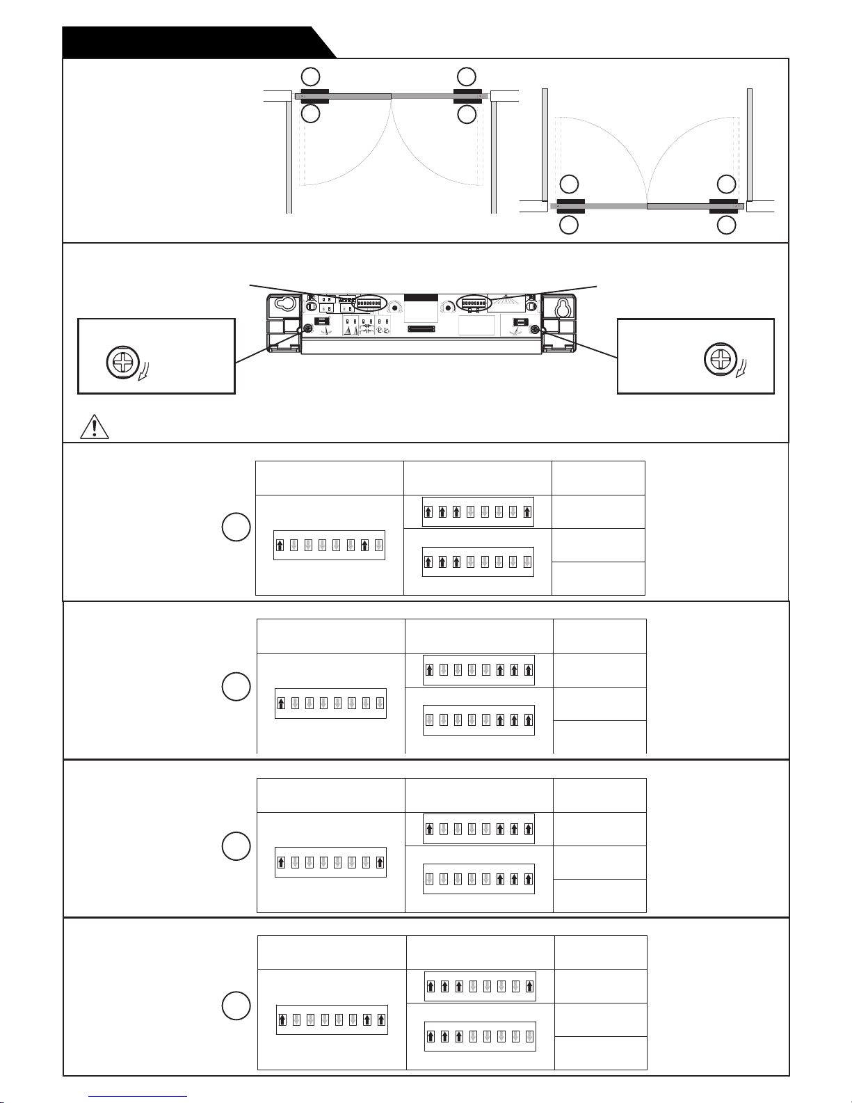
Top View
1
2
3
4
Approach Side
Swing Side
Sensor Setting
OPERATION INDICATOR
THRESHOLD AREA
SENSITIVITY
POTENTIOMETER
MaxMin
SWING AREA
SENSITIVITY
POTENTIOMETER
0deg
+5deg
‑5deg
DEEP
SHALLOW
SWING AREA DEPTH ADJUSTMENT
0deg
+5deg
‑5deg
DEEP
SHALLOW
FREQUENCY SWITCH
132
3
Each number of Area
can be eliminated
by using each dip‑SW.
AREA WIDTH SWITCH
OA-603
DEEP
SHALLOW
DEEP
SHALLOW
DEEP
PATTERN
SHALLOW
PATTERN
THRESHOLD AREA DEPTH ADJUSTMENT
AUTO LEARNING TIMER
12
15SEC.
12
12
12
6
DEEP
6
SHALLOW
AREA DEPTH
MaxMin
5
NORMAL
5
SNOW
SNOW MODE
30SEC.60SEC.120SEC.
:Stand‑by
:Doorside Det.
Green
Red Blink
Red
Yellow Blink
:Teaching
:Presence Det.
OPERATION INDICATOR
4
NORMAL
4
RAIN
RAIN MODE
Active Inactive
1 2 3
4 5
6 7 8
CONNECTOR
CONNECTOR
DEEP
PATTERN
SHALLOW
PATTERN
HINGE SIDE
7
RIGHT SIDE
7
LEFT SIDE
SENSOR SIDE
SWING SIDEAPPROACH SIDE
8 8
These DipSW(7,8) are only for door mount.
5728770
MODE SETTING SW
(LEFT DIPSWITCH)
AREA WIDTH SW
(RIGHT DIPSWITCH)
Threshold Area
Angle Screw
Swing Area
Angle Screw
Adjust both angle screws (threshold and swing) CLOCKWISE to
achieve
maximum angle for all door mount sensor
.
The screws will continue to turn even though maximum angle is
reached as indicated by the angle gauges.
Please refer to the following for the setting of the DipSwitch.
DipSwitch Setting1
DipSwitch Setting2
DipSwitch Setting3
DipSwitch Setting4
2
3
1
4
DOOR SIZE
36 inch
42 inch
48 inch
MODE SETTING SW
(LEFT DIPSWITCH)
AREA WIDTH SW
(RIGHT DIPSWITCH)
1 2 3 4 5 6 7 8
1 2 3 4 5 6 7 8
1 2 3 4 5 6 7 8
Simultaneous Pair Shown in Diagram
Single Swing Sensor Settings:
RH swing = 1 & 3
LH swing = 2 & 4
Double Egress Sensor Settings:
Both RH swings = 1 & 3 both door leafs
Both LH swings = 2 & 4 both door leafs
INSTALLATION
WARNING
Insure proper setting of Mode switch #8 indicating Approach side or Swing side sensor
.
Set +5degrees
Set +5degrees
DOOR SIZE
36 inch
42 inch
48 inch
MODE SETTING SW
(LEFT DIPSWITCH)
AREA WIDTH SW
(RIGHT DIPSWITCH)
1 2 3 4 5 6 7 8
1 2 3 4 5 6 7 8
1 2 3 4 5 6 7 8
DOOR SIZE
36 inch
42 inch
48 inch
MODE SETTING SW
(LEFT DIPSWITCH)
AREA WIDTH SW
(RIGHT DIPSWITCH)
1 2 3 4 5 6 7 8
1 2 3 4 5 6 7 8
1 2 3 4 5 6 7 8
DOOR SIZE
36 inch
42 inch
48 inch
MODE SETTING SW
(LEFT DIPSWITCH)
AREA WIDTH SW
(RIGHT DIPSWITCH)
1 2 3 4 5 6 7 8
1 2 3 4 5 6 7 8
1 2 3 4 5 6 7 8
1-2
1
2
3
4
Approach Side
Swing Side
Page 3
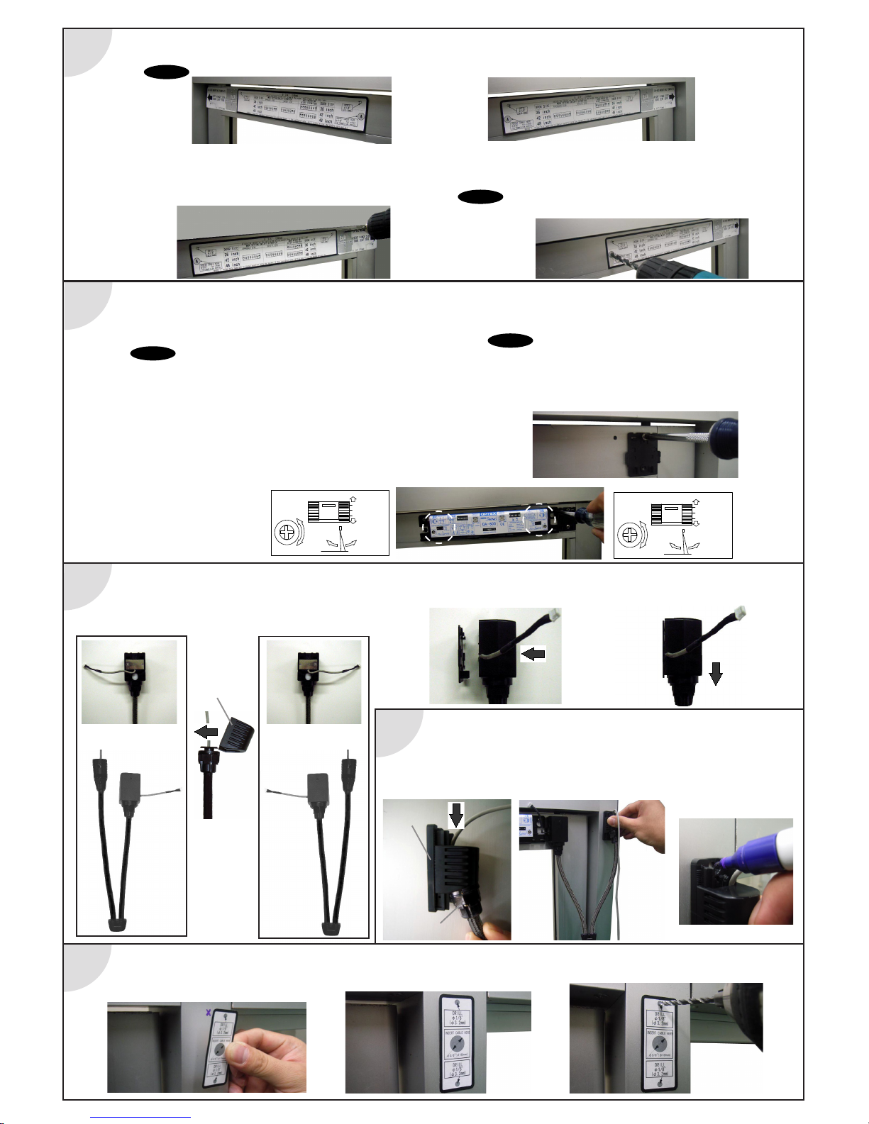
Setp 5
Step 3
Step 2
Step 1
6. Remove the template and securely fasten the sensor head to the
door using two mounting screws.
7. Repeat this process for each door leaf.
Step 4
Wiring Cover
Wiring Base
Making top of Wiring Base
Push it from the upper part a little.
Slide it from the upper part downward.
1. To attach the position sensor/door loop to the base
plate, route the sensor connector wire and change the
direction of the wiring cover based on hinge location
when facing the door (LH or RH see pictures below).
3. Drill four sensor mounting holes (two on each side of door leaf, 1/8” or 3.2 mm)
as indicated by templates.
4. Drill 3/8" holes for pass thru cable as indicated on templates.
Hole "A" on approach side templete should be perfectly in line with
hole "A" on swing side template.
1. Determine which side of door(swing or non-swing) door loop is too be installed. Align template to pivot edge of door accordingly.
Affix template. Template height can be between 6'-7" to 8'-2" from floor to top of template.
When templates are aligned properly the 3/8" pass thru hole ( "A" on template) will be aligned with each other on both sides of door.
2. On side of door the door loop is to be installed, drill two
1/8"(3.2mm) holes for position sensor mounting plate as indicated
by template (one side of door leaf only).
1. On the side of the door where the door loop is to be installed take a
603 sensor head and adjust the left and right dipswitch settings as indi
cated by the corresponding template. Verify Threshhold and Swing angle
adjustments are set to Deep (+5 degrees).
2. Remove the template and attach the sensor head loosely to the door
leaf with two of the nine supplied screws.
3. Align the position sensor mounting plate with the appropriate mounting
holes and securely fasten to the door leaf with two mounting screws.
4. Go back and tighten the screws securing the 603 sensor head to the door.
5. On the opposite side of the door leaf, take a 603 sensor head and set
the left and right dipswitch settings as indicated by the corresponding
template. Verify Threshhold and Swing angle adjustments are set to
Deep (+5 degrees).
EACH TEMPLATE LOCATION WILL HAVE DIFFERENT DIPSWITCH SETTINGS.
NOTE
2. To attach to base plate locate the position sensor slightly high and to the side
of the plate. Slide in horizontally and then down vertically .
1.To properly locate the door jamb wiring base, slide the wiring cover on to the wiring
base and center it from top to bottom.
2.Hold wiring base on jamb rotate door from closed to full open. Ensure no excessive
streching or binding of the loop occurs (may need to move base up or down to
achieve.) Mark top of wiring base to align mounting template later.
Wiring Cover
LH
RH
LH
RH
1.Align and affix top of template with mark achieved in step 4..
2.Drill two 1/8" (3.2mm) mounting holes. Drill 3/8" (10mm) hole if routing cable thru jamb for concealed wiring (3/8" hole not required for surface
wiring applications).
1-3
NOTE
These settings are optimal for most applications. However, operating conditions, environmental conditions and traffic flow may require changes to these
settings. For in depth explanations of adjustments and dipswitch settings refer
to the adjustment section (page 1-5) of this manual.
0deg
+5deg
‑5deg
DEEP
SHALLOW
DEEP
SHALLOW
DEEP
PATTERN
SHALLOW
PATTERN
0deg
+5deg
‑5deg
DEEP
SHALLOW
DEEP
SHALLOW
DEEP
PATTERN
SHALLOW
PATTERN
NOTE
NOTE
Page 4

Step 10
Step 8
Step 9
Step 6
1. For concealed wiring feed the connector thru the wiring base and then the 3/8" cable hole and into the header. For surface wiring
(see note below) do not route wire thru the wiring base.
2.Properly position and securely fasten the wiring base to the jamb (small screw located on side of wiring base indicates bottom of base).
3.Feed the remainder of the cable thru the base and into the header then slide the wiring cover onto the wiring base from the top down.
Step 7
1.Temporarily position the wiring cover on the center of the base vertically.
1.Open and close the door leaf to determine the best location for the wiring cover on the base plate.
On applications where the loop is mounted on the swing side, make sure the loop does not touch the door panel throughout the door travel.
2.Once the ideal position is determined, turn the screw in the back of the cover clockwise to secure the cover in place.
1. Remove knockouts for OA 603 sensor cover on loop side only!
2. Connect the cable from position sensor to the OA-603.
3. Connect pass thru cable to both OA-603 sensor heads.
How to remove the cover
Hold the top and remove the cover.
Place the cover on the top then fit it on.
Insert the flathead screw driver
and push it down
as shown in the picture.
If desired, sensor covers can be left off until initial setup and final adjustments are performed.
NOTE
Examples of surface wiring. Supplied flexible wire shroud is cut to fit on site.
NOTE
Step 11
Threshold Area
Sensitivity
Potentiometer
1-4
Complete wiring of OC-904 and perform intitial setup. Refer to OC-904 instruction manual and Wiring Matrix for wiring details.
Refer to Elite manual (page 1-6) for initial setup details. Once complete return to step 11.
KNOCK OUT
Page 5

A
B
C
D
E
F
2000 (6'7")
G
H
I
J
186 (7")
360 (1'2")
152 (6")
840 (2'9")
1650 (5'5")
252 (10")
593 (1'11")
89 (3")
911 (3')
K
L
M
N
O
407 (1'4")
1275 (4'2")
770 (2'6")
1684 (5'6")
1180 (3'10")
2300 (7'6")
214 (8")
414 (1'4")
175 (7")
966 (3'2")
1898 (6'2")
645 (2'1")
141 (6")
1010 (3'4")
506 (1'8")
1428 (4'8")
924 (3')
1900 (6'3")
1395 (4'7")
3
3
1 2
1
2 1 2
1 2
1 2
15 Sec 30 Sec 60 Sec 120 Sec
OPERATION INDICATOR
THRESHOLD AREA
SENSITIVITY
POTENTIOMETER
MaxMin
SWING AREA
SENSITIVITY
POTENTIOMETER
0deg
+5deg
‑5deg
DEEP
SHALLOW
SWING AREA DEPTH ADJUSTMENT
0deg
+5deg
‑5deg
DEEP
SHALLOW
FREQUENCY SWITCH
132
3
Each number of Area
can be eliminated
by using each dip‑SW
.
AREA WIDTH SWITCH
OA-603
DEEP
SHALLOW
DEEP
SHALLOW
DEEP
PATTERN
SHALLOW
PATTERN
THRESHOLD AREA DEPTH ADJUSTMENT
AUTO LEARNING TIMER
1 2
15SEC.
1 2
1 2
1 2
6
DEEP
6
SHALLOW
AREA DEPTH
MaxMin
5
NORMAL
5
SNOW
SNOW MODE
30SEC. 60SEC.120SEC.
:Stand‑by
:Doorside Det.
Green
Red Blink
Red
Yellow Blin
k
:Teaching
:Presence Det.
OPERATION INDICATOR
4
NORMAL
4
RAIN
RAIN MODE
Active Inactive
1 2 3
4 5
6 7 8
CONNECTOR
CONNECTOR
DEEP
PATTERN
SHALLOW
PATTERN
HINGE SIDE
7
RIGHT SIDE
7
LEFT SIDE
SENSOR SIDE
SWING SIDEAPPROACH SIDE
8 8
These DipSW(7,8) are only for door mount.
5728770
2
1
OPERATION INDICATOR
THRESHOLD AREA
SENSITIVITY
POTENTIOMETER
MaxMin
SWING AREA
SENSITIVITY
POTENTIOMETER
SWING AREA DEPTH ADJUSTMENT
0deg
+5deg
‑5deg
DEEP
SHALLOW
Each number of Area
can be eliminated
by using each dip‑SW.
AREA WIDTH SWITCH
OA-603
DEEP
SHALLOW
DEEP
PATTERN
SHALLOW
PATTERN
MaxMin
:Stand‑by
:Doorside Det.
Green
Red Blink
Red
Yellow Blin
k
:Teaching
:Presence Det.
OPERATION INDICATOR
Active Inactive
1 2 3
4 5
6 7 8
CONNECTOR
5728770
Adjusting the Sensitivity
Threshold Area
Sensitivity
Potentiometer
Swing Area
Sensitivity
Potentiometer
(Factory setting : Midpoint)
(Factory setting : Midpoint)
Two different frequencies can be set by adjusting Dipswitches 3 .
When two or more sensors are mounted close to each other, they
may interfere. When that happens, change Frequency .
Setting the Auto Learning Timer
(1) Select the Auto re-learning time.
(2) Turn the power on.
(3) Wait for 15 seconds to complete the initial setting.
(Factory setting : 30sec)
2-1
2-2
Setting the Frequency Function
(Interference Prevention)
1,2: Auto Learning Timer
3: Frequency
Dipswitches
Mode Dipswitch Settings(Left Bank)
2-3
Setting the Rain Mode
Setting the Snow Mode
2-4
Set this switch to Rain if the sensor is used in a region with a lot of rain.
Set this switch to Snow if the sensor is used in a region with snow or
a lot of insects.
4: Rain Mode
5: Snow Mode
44
RainNormal
55
SnowNormal
Prior to initial set up set learn time to 30seconds or longer.
ADJUSTMENTS
H
J
L
N
Sensor Pattern
B
C
D
E
F
G
I
K
M
O
A
[mm (feet)]
The sensor pattern shown is when the Swing & Threshold
area depth adjustments are set to 5 degrees. When the
sensor system performs an intial setup to its operating
environment detection
areas may vary slightly
from this chart.
NOTE
2-5 2-6
Setting the Hinge Side
Setting the Sensor Side
2-7
Setting the Area Depth
6
DEEP
6
SHALLOW
7
RIGHT SIDE
7
LEFT SIDE SWING SIDE
8 8
APPROACH SIDE
Change this switch to SHALLOW
if false detections occur from cross traffic/side
traffic/or close
by objects.In SHALLOW Mode the
shallow pattern is applied only during the opening
and closing cycles.
7
RIGHT SIDE
7
LEFT SIDE SWING SIDE
8 8
APPROACH SIDE
8 8
APPROACH SIDE
When facing the OA-603 sensor head, if the hinge is to
the right of the sensor set dipswitch to "RIGHT SIDE".
If hinge is to the left of the sensor set the dipswitch to
"LEFT SIDE".
If you installthe OA-603 sensor head on swing side,
choose
'SWING SIDE',
if non-swing side,choose 'APPROACH SIDE'.
CAUTION
Sensor system does not operate when these Dipswitches are set the same on both sides of door.
1-5
Page 6

More than
1 sec.
Reset
completed
or
More than
1 sec.
Reset
completed
CHECKING
Setup Process
This sequence must occur when power is applied for the first time or when initiating setup.
1-6
When changing sensor settings,put any OA-603 DipSW to ON/OFF for more than 1 second.
How to initiate a setup
This sensor has the function to fit floor condition changes automatically.
Therefore, even if objects are put in the detection area, sensor will learn the changes
gradually and set back to normal operations automatically after several detections.
Auto learning function
At full closed if setup does not complete in less than 5 seconds initiate setup again.
Door Status
Sensor
Status
Operation Indicator
Swing Side
Approach Side
Initial Setup
door closed
Yellow Blinking
Solid Yellow
Yellow Blinking
Aproxinately 8sec.
Activate door
to learn opening
cycle
Do not enter the detection area,
untill indicater turn to solid yellow.
Waiting for
next learning
Solid Yellow
Solid Yellow
Blinking Yellow
Solid Orange
Learning
Full Opened Cycle
Blinking Yellow
Solid Orange
Blinking Red
Blinking Yellow
Aproxinately 8sec.
Learning
Closing Cycle
Blinking Yellow Blinking Yellow
Setup complete
approximately
3sec. after
full closed
OC-904
Operation Indicator
Blinking Green
Solid Green
Blinking Green
Solid Orange
Solid Orange
Solid Green
Solid Green
(See Note)
Solid Green
(See Note)
Blinking Green
Solid Green
NOTE
Page 7

CHECKING
Operation Check
Before leaving the site, check five items in the right table.
1-7
Page 8

Warning Indication (OA-603 Sensor head)
TROUBLE SHOOTING
Advise the building owner/operator of the following items
1. When turning the power on, stay clear of detection area for a minimum of 10 seconds then walk test detection
area to ensure proper operation.
2. Always keep the detection window clean. If dirty, wipe the window with a damp cloth ( Do not use any cleaner or solvent ).
3. Do not wash the sensor with water.
4. Do not disassemble, rebuild or repair the sensor yourself; otherwise electric shock may occur.
5. Contact your installer or the sales engineer if you want to change the settings.
6. Do not place an object that moves or emits light in the detection area.(ex. Plant, illumination etc..)
7. Do not paint the Detection Window.
“Take Care of Environment”. This manual uses recycled paper.
OPTEX CO.,LTD.
(ISO 9001 Certified by LRQA)
5-8-12 ogoto Otsu,
520-0101 Japan
TEL.: +81 (0)77-579-8700
FAX : +81 (0)77-579-7030
WEBSITE: www.optex.co.jp
Secumatic b.v.
Tiber 2 . 2491 DH The Hague , P.O. Box 24009
2490 AA The Hague The Netherlands
TEL.: +31 (0)70 419 41 00
FAX : +31 (0)70 317 73 21
E-MAIL: info@secumatic.nl
WEBSITE: www.secumatic.nl
Optex Technologies, Inc.
3882 Del Amo Blvd., Suite 604,
Torrance, CA 90503-2184, USA
TEL: +1 (310) 214-8644
FAX: +1 (310) 214-8655
TOLL-FREE: +1 (800) 877-6656
WEBSITE: www.optexentrances.
com
Contact your installer or the sales engineer if:
- you need to change the settings or replace the sensor.
- the trouble still persists after checking and remedying as described above.
1-8
Symptom Possible cause Solution
OC-904C no LED indication
OC-904C LED double orange flashing & no LED
indication on OA-603
CANNOT INITIATE SETUP
WILL NOT COMPLETE INITIAL SETUP
Improper power supply Correct power problem
Bad connection on Orange and Brown wires of OC-904
Repair bad connection
Bad connection at OC-904
Reseat 4 pin connector from Loop assy to OC-904
Bad connection from loop assy
To OA-603 sensor head
Reseat 4 pin connector from loop assy to OA- 603 sensor head
Bad connection with 7" pass thru cable
Reseat connection of 7" cable to both OA-603 sensor heads
Bad 7" cable
Replace as necessary
OC-904 LED double orange flashing & erratic LED
on OA-603 sensors
Switches 7 & 8 of left dipswitches on OA-603 sensors set wrong
Correct dipswitch settings see pg 1-2
OC-904 dipswitches set wrong
Check Connection Matrix for proper dipswitch settings
Poor or improper connection of yellow wires from OC-904 to door control
Check Connection Matrix for proper connection of yellow wires
Improper voltage on red & black wire of OC-904
Ensure positive voltage on red wire at hold open and 0 voltage
at closed position
INTERMITENT RECYCLE (ghosting) OR INTERMITENT STALLING
After initial setup door ghosts several times on first activation
Happens on 15% of installations
If stops after first activation, system is OK
OA-603 sensor head not mounted flush on door
Head may be resting on top of loop mounting bracket
Reposition head flush on panel
Improper threshold or swing area angle adjustment
Set threshold and swing area angles at +5 degrees (deep)
Improper voltage on red & black wire of OC-904
Ensure positive voltage on red wire at hold open and 0 voltage
at closed position
Stalling caused by traffic just outside of swing path or objects
near guide rails
Set switch 6 on left bank dipswitch of OA-603 on/up (shallow)
Note: moving the dipswitch will initiate a setup
Area width dipswitches set wrong
(right bank dipswitches on OA-603)
Verify proper settings (page 1-2)
Inconsistent data from position sensor/loop assy
Postion the loop assy so loop center coupler does not rest on
door at any point of door travel
NO ACTIVATION AND/OR NO REACTIVATION ON CLOSING CYCLE
OC-904 yellow wires poor or improper connection to door control
or on/off/hold switch
Verify proper connection and output of yellow wires.
(see Elite Connection Matrix)
OC-904 dipswitches set improperly
Verify proper settings(see Elite Connection Matrix)
On knowing act applications poor or improper connection of
purple wires from OC-904 to activation device
Verify good and proper connection (see OC-904 install manual)
NO SAFETY ON SWING SIDE AT FULL
CLOSED
OA -603 sensor detects (solid or flashing red LED)
but door opens anyway
Poor or improper connection of Blue wires from OC-904 to door
control
Verify good and proper connection of blue wires
(see Elite Connection matrix)
OC-904 dipswitches set improperly
Verify proper settings (see Elite Connection Matrix)
OA-603 no detection (solid green LED)
Area width dipswitches set wrong
(right bank dipswitches on OA-603)
Verify proper settings (page 1-2)
NO STALL ON SWING SIDE WHILE
DOOR IS OPENING
OA -603 sensor detects (solid or flashing red LED)
but door does not slow or stop
Poor or improper connection of green wires from OC-904 to door
control
Verify good and proper connection of Green wires
(see Elite Connection matrix)
OC-904 dipswitches set improperly
Verify proper settings (see Elite Connection Matrix)
OA-603 no detection (solid green LED)
Area width dipswitches set wrong
(right bank dipswitches on OA-603)
Verify proper settings (page 1-2)
DOOR REMAINS OPEN
OC-904 dipswitches set improperly
Verify proper settings (see Elite Connection Matrix)
On knowing act applications poor or improper connection of
purple wires from OC-904 to activation device
Verify good and proper connection (see OC-904 install manual)
Improper wiring of door equipment on/off/hold switch
Verify proper wiring of on/off/hold switch
Moving dipswitch on OA-603 does not
result in OA-603 LED fast flash yellow.
Mode
Self Monitoring Function
Life cycle Notification Signal Saturation Communication Error Setting Error
Operation Indicator
Explanation
Fast Green Blinking Twice Green Blinking Slow Green Blinking
The sensor is reaching the
end of its life cycle
.
The relay is reaching the
end of its life cycle
.
Either the mounting position is too
low or the detection area includes
the wall or another object.
OA-603 threshold angle may be
set to less than +5 degrees deep
.
Refer to "ADJUSTMENT".
The sensor cable is connected,
but unstable communication.
A sensor cab
le may be
disconnected or OA-603 mode
switches 7 & 8 may be set wrong.
Refer to "ADJUSTMENT
"
When all the area width switches
are inactive.
Refer to "ADJUSTMENT".
Fast Orange Blinking
Twice Orange Blinking
Page 9

PUSH
TO OPEN
OA-603
OA-603
Position Sensor
Activate Input
Safety Input
Yellow
Blue
Door Controller
Motor
Red
+ -
Black
Brown
Orange
POWER
12-24 AC
12-30 DC
OC-904C
Sensor Cable
Green
Stall Input
Purple
Activate Signal
(N.O.only)
Relay1
Output
Relay2
Delaye
d
Output
Time Delay Module
Activation
Input
Knowing Act
Devices
(i.e.Push Plate)
Push Plate
OR
Electric
Lock
75 (3")
38.5 (1 1/2)
26 (1")
(0.5~10sec)
SAFETY
OUTPUT
ACTIVATE
OUTPUT
MOTOR
INPUT
YELLOWBLUE
RED
BLACK
ORANGE
BROWN
:
:
:
:
POWER:AC 12‑24V,DC 12‑30V
N.O. N.C.
Auto
Knowing
Act
OC‑904C
SAFETY
OUTPUT
HOLD TIME
MaxMin MaxMin
SAFETY
RELAY CONTACT
ACTIVATION
OPERATION
5728760
POWER
:
ACTIVATE
INPUT
PURPLE
DIRECTIONAL PLUG
WIRING
1 2 3 4
(0.5~10sec)
STALL
OUTPUT
HOLD TIME
N.O. N.C.
STALL
RELAY CONTACT
STALL
OUTPUT
GREEN
:
FUTURE
DEVELOPMENT
Power Supply 12 - 24V AC, 12 - 30V DC
Current Draw 500mA max.*
Output Activate Output : Form A Relay 50V, 0.1A(Resistance Load)
Safety Output : Form C Relay 50V, 0.1A (Resistance Load)
Stall Output : Form C Relay 50V, 0.1A (Resistance Load)
Relay Hold Time(Safety&Stall Output only) 0.5 to 10s
Response Time < 0.3s
Operation Indicator Green: Standby
Red: Door Opening
Orange: Lockout
Operating Temperature -20 - +55degrees (-4F - +131Fdegrees)
Weight 50g (1.8oz.)
Accessories 1 Two sided tape
2 T-tap connector
*When a unit of the 2 OA-603 and 1 OC-904C used.
OUTER DIMENSIONS
SPECIFICATIONS
[mm (inch)]
WIRING
The specifications herein are subject to change without prior notice due to improvements.
OC-904C
Swing Door
Sensor Controller
ADJUSTMENT
Dipswitch Settings
INSTALLATION
MANUFACTURER'S STATEMENT
Use the T-tap connector unless there are wiring terminals
Stall Output
Hold Time
Factory setting
: 0.5sec
Safety Output
Hold Time
Factory setting
:0.5sec
3 ACTIVATION OPERATION
(factory setting:Auto)
If uses push button for activate,select the knowing act.
1 SAFETY RELAY CONTACT
(factory setting:NO)
Choose the Relay Contact.
2 STALL RELAY CONTACT
(factory setting:NO)
Choose the Relay Contact.
4 FUTURE DEVELOPMENT(NOT USED)
N.O. N.C.
(0.5-10sec)
(0.5-10sec)
SAFETY
OUTPUT
HOLD TIM
E
MaxMin MaxMin
1 2 3 4
STALL
OUTPUT
HOLD TIME
N.O. N.C. Auto
Knowing
Act
SAFETY
RELAY CONTACT
ACTIVATION
OPERATION
N.O. N.C.
STALL
RELAY CONTACT
FUTURE
DEVELOPMENT
N.O. N.C.
AUTO
KNOWING
AC
T
NOTE
For Knowing Act application,
Connect purple wire to Activate output from push button.
The approach side sensor will be inactive on full-closed position with this function.
NOTE
OC-904Cmotor wire
5913001 2008.3
2-1
For ease of installation and proper operation read thru this manual (especially
WARNING
CAUTION
NOTE
) prior to installing and adjusting the sensor system.
Failure to read and follow the instructions in this manual may cause improper sensor operation resulting in serious injury or death.
This product is a non-contact activating switch intended for door mounted of an automatic door.
Do not use it for any other applications; otherwise proper operation and safety cannot be guaranteed.
1.Set door speeds and verify proper operation of door manufacturer’s equipment prior to applying power to the sensor system.
2.Do not install the sensor where it might be directly sprayed with rainwater.
3.Verify proper wiring prior to applying power to the sensor system to prevent damage to equipment.
4.When setting the sensor’s area pattern, make sure there is no traffic around the installation site.
5.Do not attempt to rebuild or repair sensor heads or control unit. Contact an address in this manual for replacement products.
6.Only use the sensor as specified in the supplied instructions.
7.Walk test the installation to verify operation is in compliance with all local laws, codes and standards of your country.
8.Upon completion of installation and adjustments, instruct the owner/operator on proper operation of the door and sensor system.
Identify any switches/breakers that will place the door out of service when unsafe or improper operation is identified.
WARNING
CAUTION
NOTE
Disregard of warning may cause the improper use causing death or serious injury of person.
Special attention for the setting and adjustment of section of this symbol is required.
Disregard of caution may cause the improper use causing injury of person or damage to
object.
How t o use T- t ap con n ector
Close connector
Door
Controller
motor wire
Hold Open
ACT
COM
ACT
OC-904
Auto
Off
Standard Optional On / Off / Hold Switch
OEM
Door
Control
Motion
Sensor
For manufacture specific connections
refer to the Connection Matrix.
Page 10

“Take Care of Environment”. This manual uses recycled paper.
OPTEX CO.,LTD.
(ISO 9001 Certified by LRQA)
5-8-12 ogoto Otsu,
520-0101 Japan
TEL.: +81 (0)77-579-8700
FAX : +81 (0)77-579-7030
WEBSITE: www.optex.co.jp
Secumatic b.v.
Tiber 2 . 2491 DH The Hague , P.O. Box 24009
2490 AA The Hague The Netherlands
TEL.: +31 (0)70 419 41 00
FAX : +31 (0)70 317 73 21
E-MAIL: info@secumatic.nl
WEBSITE: www.secumatic.nl
Contact your installer or the sales engineer if:
- you need to change the settings or replace the sensor.
- the trouble still persists after checking and remedying as described above.
Optex Technologies, Inc.
3882 Del Amo Blvd., Suite 604,
Torrance, CA 90503-2184, USA
TEL: +1 (310) 214-8644
FAX: +1 (310) 214-8655
TOLL-FREE: +1 (800) 877-6656
WEBSITE: www.optexentrances.
com
Warning Indication (OC-904C Controller)
TROUBLESHOOTING
Advise the building owner/operator of the following items
2-2
1. When turning the power on, stay clear of detection area for a minimum of 10 seconds then walk test detection
area to ensure proper operation.
2. Always keep the detection window clean. If dirty, wipe the window with a damp cloth ( Do not use any cleaner or solvent ).
3. Do not wash the sensor with water.
4. Do not disassemble, rebuild or repair the sensor yourself; otherwise electric shock may occur.
5. Contact your installer or the sales engineer if you want to change the settings.
6. Do not place an object that moves or emits light in the detection area.(ex. Plant, illumination etc..)
7. Do not paint the Detection Window.
Symptom Possible cause Solution
OC-904C no LED indication
OC-904C LED double orange flashing & no LED
indication on OA-603
CANNOT INITIATE SETUP
WILL NOT COMPLETE INITIAL SETUP
Improper power supply Correct power problem
Bad connection on Orange and Brown wires of OC-904
Repair bad connection
Bad connection at OC-904
Reseat 4 pin connector from Loop assy to OC-904
Bad connection from loop assy
To OA-603 sensor head
Reseat 4 pin connector from loop assy to OA- 603 sensor head
Bad connection with 7" pass thru cable
Reseat connection of 7" cable to both OA-603 sensor heads
Bad 7" cable
Replace as necessary
OC-904 LED double orange flashing & erratic LED
on OA-603 sensors
Switches 7 & 8 of left dipswitches on OA-603 sensors set wrong
Correct dipswitch settings see pg 1-2
OC-904 dipswitches set wrong
Check Connection Matrix for proper dipswitch settings
Poor or improper connection of yellow wires from OC-904 to door control
Check Connection Matrix for proper connection of yellow wires
Improper voltage on red & black wire of OC-904
Ensure positive voltage on red wire at hold open and 0 voltage
at closed position
INTERMITENT RECYCLE (ghosting) OR INTERMITENT STALLING
After initial setup door ghosts several times on first activation
Happens on 15% of installations
If stops after first activation, system is OK
OA-603 sensor head not mounted flush on door
Head may be resting on top of loop mounting bracket
Reposition head flush on panel
Improper threshold or swing area angle adjustment
Set threshold and swing area angles at +5 degrees (deep)
Improper voltage on red & black wire of OC-904
Ensure positive voltage on red wire at hold open and 0 voltage
at closed position
Stalling caused by traffic just outside of swing path or objects
near guide rails
Set switch 6 on left bank dipswitch of OA-603 on/up (shallow)
Note: moving the dipswitch will initiate a setup
Area width dipswitches set wrong
(right bank dipswitches on OA-603)
Verify proper settings (page 1-2)
Inconsistent data from position sensor/loop assy
Postion the loop assy so loop center coupler does not rest on
door at any point of door travel
NO ACTIVATION AND/OR NO REACTIVATION ON CLOSING CYCLE
OC-904 yellow wires poor or improper connection to door control
or on/off/hold switch
Verify proper connection and output of yellow wires.
(see Elite Connection Matrix)
OC-904 dipswitches set improperly
Verify proper settings(see Elite Connection Matrix)
On knowing act applications poor or improper connection of
purple wires from OC-904 to activation device
Verify good and proper connection (see OC-904 install manual)
NO SAFETY ON SWING SIDE AT FULL
CLOSED
OA -603 sensor detects (solid or flashing red LED)
but door opens anyway
Poor or improper connection of Blue wires from OC-904 to door
control
Verify good and proper connection of blue wires
(see Elite Connection matrix)
OC-904 dipswitches set improperly
Verify proper settings (see Elite Connection Matrix)
OA-603 no detection (solid green LED)
Area width dipswitches set wrong
(right bank dipswitches on OA-603)
Verify proper settings (page 1-2)
NO STALL ON SWING SIDE WHILE
DOOR IS OPENING
OA -603 sensor detects (solid or flashing red LED)
but door does not slow or stop
Poor or improper connection of green wires from OC-904 to door
control
Verify good and proper connection of Green wires
(see Elite Connection matrix)
OC-904 dipswitches set improperly
Verify proper settings (see Elite Connection Matrix)
OA-603 no detection (solid green LED)
Area width dipswitches set wrong
(right bank dipswitches on OA-603)
Verify proper settings (page 1-2)
DOOR REMAINS OPEN
OC-904 dipswitches set improperly
Verify proper settings (see Elite Connection Matrix)
On knowing act applications poor or improper connection of
purple wires from OC-904 to activation device
Verify good and proper connection (see OC-904 install manual)
Improper wiring of door equipment on/off/hold switch
Verify proper wiring of on/off/hold switch
Moving dipswitch on OA-603 does not
result in OA-603 LED fast flash yellow.
Mode
Life cycle Notification Communication Error
Operation Indicator
Explanation
Twice Green Blinking
The relay is reaching the
end of its life cycle.
Twice Orange Blinking
The sensor cable is connected,
but unstable communication.
A sensor cab
le may be
disconnected or OA-603 mode
switches 7 & 8 may be set wrong.
Refer to "ADJUSTMENT"
 Loading...