

Page 1
MOUNTING TEMPLATE
ENGLISH
operation
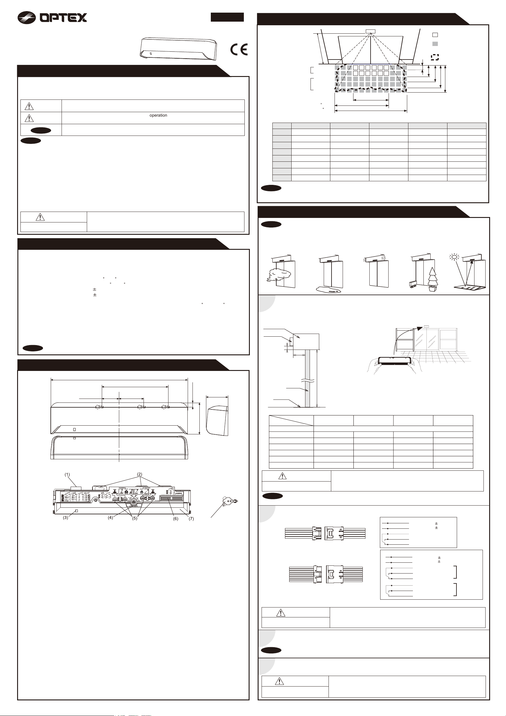
DETECTION AREA
OA-AXIS I / II
MANUFACTURER'S STATEMENT
Read this operation manual carefully before use to ensure proper operation of the sensor.
Failure to read this operation manual may cause improper sensor operation and may result in serious injury or death of
person.The meanings of the symbols are as follows. Please study the following first and then read the contents of this
operation manual.
5915031 JAN 2009
WARNING
CAUTION
NOTE
NOTE
1. This sensor is a non-contact switch intended for header mount / wall mount of an automatic door.
Do not use for any other applications. This sensor cannot be used for industrial doors or shutters,
when used, proper operation and safety cannot be guaranteed.
2. When setting the sensor's detection area, make sure there is no traffic around the installation site.
3. Before turning the power on, check the wiring to prevent damage or malfunction of equipments that are connected
to the sensor.
4. Only use the sensor as specified in the operation manual provided.
5. Be sure to install the sensor in accordance with the local laws and standards of the country in which the sensor is
installed.
6. Before leaving the job site make sure that the sensor is operating properly and instruct the building owner/operator
on proper operation of the door and the sensor.
7.The sensor setting can only be changed by an installer or service engineer. When changed, register the changed
setting and dates in the maintenance logbook accompanying the door.
Danger of electric shock.
SPECIFICATIONS
Model
Cover color
Mounting height
Detection area
Detection method
Depth angle adjustment
Power supply
Power consumption
Operation LED
NOTE
The specifications herein are subject to change without prior notice due to improvements.
Disregard of warning may cause the improper operation causing death or serious injury of
person.
Disregard of caution may cause the improper
objects.
Special attention is required to the section of this symbol.
WARNING
: OA-AXIS I / OA-AXIS II
: Silver / Black
: 2.0 (6'7") to 3.5m (11'5")
: See DETECTION AREA
: Active Infrared Reflection
: 1st to 3rd rows / -6 to +6
4th and 5th rows / +26 to +44
: 12 to 24VAC( 10%)
12 to 30VDC( 10%)
: OA-AXIS I < 3VA
OA-AXIS II < 4VA
: Green / Stand-by
Blinking Red / 1st row detection
Red / 2nd row detection
Orange / 3rd to 5th rows detection
Do not wash, disassemble, rebuild or repair the sensor, otherwise
it may cause electric shock or breakdown of equipments.
Output
Output hold time
Response time
Operating temperature
IP rate
Weight
Accessories
causing injury of person or damage to
: OA-AXIS I /
Form C relay
50V 0.3A Max.(Resistance load)
OA-AXIS II /
1st to 3rd rows / Form C relay
50V 0.3A Max. (Resistance load)
3rd to 5th rows / Form C relay
50V 0.3A Max.(Resistance load)
: Approx. 0.5 sec.
: <0.3 sec.
: -20 to +55 C(-4 to 131 F)
: IP44
: 320g (11.2oz)
: 1 Cable 3m (9'10")
1 Operation manual
2 Mounting screws
1 Mounting template
1 Area adjustment tool
A
Motion / Presence
detection
Motion detection
Sensor setting
1st to 3rd rows : +6
4th and 5th rows : +44
A
B
C
D
E
F
G
H
I
NOTE
The actual detection area may become smaller depending on the ambient light, the color / material of the
object or the floor as well as the entry speed of the object.
*The values of the chart above is of the emitting spots, but not of the detection area.
1st row
2nd row
3rd row
4th row
5th row
2.20(7'2 5/8")
0.14(5 1/2")
0.42(1'4 9/16")
0.82(2'8 5/16")
1.35(4'5 1/8")
1.90(6'2 13/16")
1.33(4'4 3/8")
2.05(6'8 11/16")
2.78(9'1 7/16")
H
2.50(8'2 7/16")
0.16(6 5/16")
0.48(1'6 7/8")
0.93(3' 5/8")
1.54(5' 5/8")
2.17(7'1 7/16")
1.51(4'11 7/16")
2.32(7'7 5/16")
3.15(10'4")
GG
I
2.70(8'10 5/16")
0.18(7 1/16")
0.52(1'8 1/8")
1.00(3'3 3/8")
1.66(5'5 3/8")
2.34(7'8 1/8")
1.63(5'4 3/16")
2.51(8'2 13/16")
3.40(11'1 7/8") 3.79(12'5 3/16")
B
3.00(9'10 1/8")
0.20(7 7/8")
0.58(1'10 13/16")
1.10(3'7 5/16")
1.85(6' 13/16")
2.60(8'6 3/8")
1.81(5'11 1/4")
2.79(9'1 13/16")
INSTALLATION
NOTE
1
Header
Sensor
The following conditions are not suitable for the sensor installation.
-Fog or exhaust emission around the door.
-Wet floor
-Vibrating header or mounting surface.
-Moving objects or a heating radiator in the detection area.
-Highly reflecting floor or the presence of highly reflecting objects around the door.
1. Affix the mounting template at the desired mounting position.
2. Drill two mounting holes of ø3.4mm (ø1/8”).
3. To pass the cable through to the header, drill a wiring hole of ø8mm (ø5/16”).
4. Remove the mounting template.
5. Remove the housing cover. Attach the sensor to the mounting surface with two mounting screws.
Y
X
.
: Emitting spots
: Emitting spots
(Can be elminated)
: Detection area
C
D
E
F
3.50(11'5 13/16")
0.23(9 1/16")
0.67(2'2 3/8")
1.30(4'3 3/16")
2.16(7'1 1/16")
3.03(9'11 5/16")
2.11(6'11 1/16")
3.26(10'8 3/8")
4.42(14'6")
[m(feet,inch)]
OUTER DIMENSIONS AND PART NAMES
267(10 1/2")
36(1 7/16")
(1) Connector
(2) Mounting holes
(3) Operation LED
(4) Depth angle adjustment screw
43(1 11/16")
125(4 15/16")
(5) Width adjustment screws
(6) Dipswitches
(7) Detection window
(8) Area adjustment tool
7.5(5/16")
62.3(2 7/16")
(8)
45(1 3/4")
[mm (inch)]
H
Door
Floor
Maximum mounting distance (Y)
X
50 (1 15/16") 200 (7 7/8") 200 (7 7/8") 200 (7 7/8")
100 (3 15/16") 200 (7 7/8") 200 (7 7/8") 200 (7 7/8") 200 (7 7/8")
150 (5 7/8") 130 (5 1/8”) 150 (5 7/8”) 170 (6 11/16") 200 (7 7/8")
200 (7 7/8")
250 (9 13/16") 120 (4 3/4”)
300 (11 13/16") - -
H
0
CAUTION
Risk of getting caught.
NOTE
2
The sensor mounting position may be limited depending on the header thickness and the mounting height.
Wire the cable to the door controller properly as shown in the drawing below.
OA-AXIS I
OA-AXIS II
WARNING
Danger of electric shock.
H: Height from the floor to the bottom of the header
Y: Distance between the bottom of header and the sensor.
X: Distance between the door and the mounting surface
2,000 (6' 6") 2,200 (7' 2") 2,500 (8' 2") 3,000 (9' 10")
200 (7 7/8")
- 110 (4 5/16”) 130 (5 1/8”) 150 (5 7/8”)
-
Make sure to affix the mounting template as described in the above chart.
Otherwise, it can be dangerous since there may be no presence detection area
around the threshold. Install the sensor as low as possible on the header.
Before starting the procedure, ensure that the power is turned OFF.
When passing through the cable to the hole, make sure not to tear the shield,
otherwise it may cause electric shock or breakdown of the sensor.
No limit
- -
- -
}
Grey
Grey
White
Yellow
Green
Power supply
12 to 24VAC 10%
12 to 30VDC 10%
Common (COM.)
Normally open (N.O.)
Normally closed (N.C.)
Power supply
12 to 24VAC 10%
}
12 to 30VDC 10%
Common (COM.)
Normally open (N.O.)
Normally closed (N.C.)
Common (COM.)
Normally open (N.O.)
Normally closed (N.C.)
Grey
Grey
White
Yellow
Green
White Str.
Yellow Str.
Green Str.
*The outputs from the 3rd row overlaps.
[mm(feet,inch)]
3rd to 5th
rows output
1st to 3rd
rows output
*
*
1.Plug the connector of the sensor.
3
2.Supply power to the sensor. Adjust the detection area and set the dipswitches. (See ADJUSTMENTS)
NOTE
4
Make sure to connect the cable correctly to the door controller before turning the power ON.
To enable the presence detection, do not enter the detection area for 10 seconds after supplying the power.
Place the housing cover .
If wiring is to be exposed, break the knockout.
WARNING
Danger of electric shock.
Do not use the sensor without the cover.
When using the cable knockout, install the sensor indoors or use the rain-cover
(Separetely available) otherwise electric shock or breakdown of
the sensor may occur.
Page 2
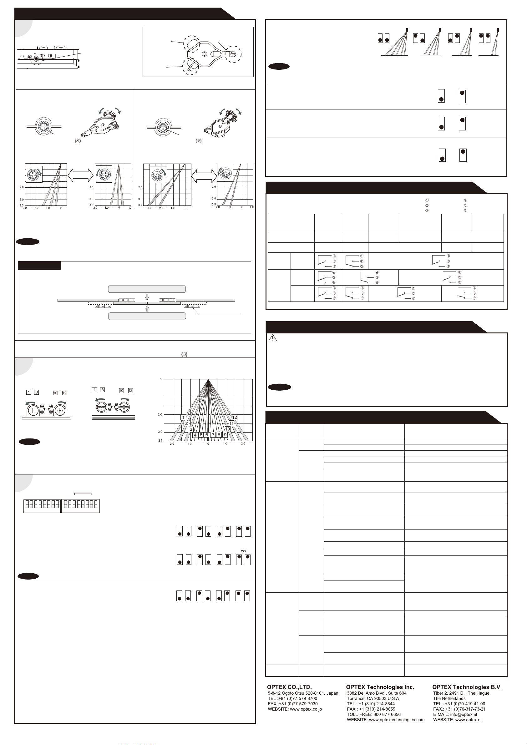
ADJUSTMENTS
Area depth angle adjustment
1
Depth angle
adjustment screw
The detection area depth can be changed by
the area adjustment tool.
When adjusting the 1st to 3rd rows close to the door, follow 3-7 Installation mode.
Area adjustment tool
1st to 3rd rows
adjustment
A
Simultaneous
adjustment
C
1-1. Independent adjustment
1st to 3rd rows
Depth angle adjustment screw
for 1st to 3rd rows
Use the area adjustment tool (A) as shown above and
change the depth of the detection area by turning the depth
angle adjustment screw.
Check the area position with Red LED of the Operation LED using a tool such as a reflecting mirror.
NOTA
NOTE
Red
Make sure the detection area does not overlap with the door / header,otherwise ghosting / signal saturation
may occur.
Do not place any highly reflecting objects in the detection area, otherwise signal saturation may occur.
Shallow
ShallowDeep
4th and 5th rows
Deep
Depth angle adjustment screw
for 4th and 5th rows
Use the area adjustment tool (B) as shown above and
change the depth of the detection area by turning the depth
angle adjustment screw.
[m][m]
Blue
ShallowDeep
4th and 5th rows and
area width adjustment
B
Shallow
Deep
3-4 Setting the area depth
The 5th, 4th, and 3rd rows can be eliminated by
combining dipswitches 7 and 8.
*When 2 rows setting is selected, only the
presence detection area remains.
NOTE
Always check the area according to the expected entry speed and determine the appropriate number
of rows.
When setting motion and motion / presence detection area sparately, make sure that there is no gap between
two areas.
3-5 Setting the snow mode
Set this switch to ON, if the sensor is used in a region with snow.
3-6 Setting the immunity
Set this switch to ON, when less influence by the header vibration is required.
3-7 Installation mode
Use this switch to ON when adjusting the presence detection area
[m][m]
close to the door face.
* During the installation mode, only the 1st row remain.
* Door open state
* Operation LED glows yellow.
5 rows 4 rows 3 rows 2 rows
7 8
7 8 7 8 7 8
OFF
9
OFF
10
OFF
16
ON
9
ON
10
ON
16
CHECKING
Check the operation according to the chart below.
Entry
Status
Operation LED
Power off
None
Outside of
detection
area
-
Stand-by
Green
Entry into
4th or 5th row
Motion
detection active
Entry into
3rd row
Motion/Presence
detection active
Orange
White : COM.
Yellow : N.O.
Green : N.C.
Entry into
2nd row
Presence
detection
Red
White Str. : COM.
Yellow Str. : N.O.
Green Str. : N.C.
Entry into
1st row
Blinking Red
REFERENCE
1. Turn the depth adjustment screw to the right (Deep) to place the area most away from the door.
2. Set INFRARED FINDER sensitivity to "H" (High) and place it on the floor as shown below.
3. Turn the depth adjustment screw to the left (Shallow) until the emitting area is placed at the position where
INFRARED FINDER is in the low detection status (Slow Red blinking).
Area depth adjustment with INFRARED FINDER (Separately available)
Detection area
Detection area
INFRARED FINDER
1-2. Simultaneous adjustment
For the simultaneous adjustment of 1st to 5th rows, use the adjustment tool (C).
2
Width detection area adjustment
Front view
1st to 3rd rows
-
Eliminated
Width adjustment
screw (Left)
NOTE
The actual detection area may become smaller depending on the ambient light, the color / material of the object and
the floor as well as the entry speed of the object.
Dipswitch settings
3
1
2
3
4 5 6
Narrow
Wide
-
Eliminated
9
7
8
10
3-1 Setting the sensitivity
Normally set to "Middle". " Low" decreases the sensitivity and "High / S-High"
increases the sensitivity.
3-2 Setting the presence detection timer
The 1st and 2nd rows have the presence detection function.
The presence detection timer can be selected from 4 settings.
NOTE
To enable the presence detection, do not enter the detection area for 10 seconds after setting the timer.
3-3 Setting the frequency
When using more than two sensors close to each other, set the different
frequency for each sensor by combining dipswitch 5 and 6.
4th and 5th rows
Eliminated
Width adjustment
screw (Right)
Not applicable
14
12
13
11
16
15
-
1,2 : Sensitivity
3,4 : Presence detection timer
5,6 : Frequency
7,8 : Row adjustment
-
Eliminated
Narrow
Wide
9
: Snow mode
10
: Immunity
11 to 15
: Not applicable
16
: Installation mode
Low Middle High
12 12
15 sec. 60 sec. 180 sec.
Setting 1
Setting 2
56 56
12
3434 34 34
Setting 3
56
Setting 4
[m]
S- High
12
56
OA-AXIS I
OA-AXIS
*The outputs from the 3rd row overlaps.
Output
Output from
1st to 3rd
rows
II
Output from
3rd to 5th
rows
*
*
INFORM BUILDING OWNER / OPERATOR OF THE FOLLOWING ITEMES
WARNING
1. Always keep the detection window clean. If dirty, wipe the window lightly with a damp cloth.
(Do not use any cleaner or solvent.)
2. Do not wash the sensor with water.
3. Do not disassemble, rebuild or repair the sensor yourself, otherwise electric shock may occur.
4. When an operation LED blinks green, contact your installer or service engineer.
5. Always contact your installer or service engineer when changing the settings.
6. Do not paint the detection window.
NOTA
NOTE
1. When turning the power on, always walk-test the detection area to ensure proper operation.
2. Do not place any objects that move or emit light in the detection area. (e.g. Plant, illumination, etc.)
TROUBLESHOOTING
Problem
Door does not
open when a
person enters
the detection
area.
Door opens
when no one
is in the
detection area.
(Ghosting)
Door remains
open
Door remains
closed
Operation
LED
None Power supply voltage. Set to the stated voltage.
Unstable
Unstable
Red
Orange
Proper
Twice
Green
blinking
Slow
Green
blinking
Proper
Wrong wiring or connection failure.
Wrong detection area positioning.
Sensitivity is too low. Set the sensitivity higher.
Short presence detection timer.
Dirty detection window. Wipe the detection window with a damp cloth.
Vibration of the header. Set the sensitivity lower or the immunity to ON.
Water drops on the detection window. Use the rain-cover (Separately available).
The detection area overlaps
with that of another sensor.
The detection area overlaps
with the door / header.
Reflecting objects in the detection area.
Or reflecting light on the floor.
Sensitivity is too high. Set the sensitivity lower.
It snows and pours.
Objects that move or emit light in the
detection area.
(Ex.Plant, illumination,etc.)
Wet floor. Check the installation condition referring to
The exhaust emission or fog pen-
etrate into the detection area.
Sudden change in the detection area.
or
Wrong wiring or connection failure.
The relay is reaching the end of its
life cycle.
Signal saturation
The detection area overlaps with
the door / header.
Wrong wiring or connection failure.
Possible cause
Check the wires and connector.
Check ADJUSTMENTS 1 & 2.
Set the presence detection timer longer.
(Do not use any cleaner or solvent.)
Or install in a place keeping the waterdrops off.
Check ADJUSTMENTS 3-3.
Adjust the detection area to "Deep" (Outside).
Remove the objects.
Set the snow mode to ON.
Remove the objects.
INSTALLATION on the reverse side.
Check ADJUSTMENTS 3-1 & 3-2.
If the problem still persists, hard-reset the
sensor.(Turn the power OFF and ON again.)
Check the wires and connector.
Contact your installer or the sales engineer.
Remove highly reflecting objects from the
detection area. Or lower the sensitivity.
Or change the area angle.
Adjust the detection area to "Deep" (Outside).
Check the wires and connector.
Possible countermeasures
 Loading...